Real-Time Embedded Multithreading Using ThreadX and MIPS- P1 potx
Bạn đang xem bản rút gọn của tài liệu. Xem và tải ngay bản đầy đủ của tài liệu tại đây (231.5 KB, 20 trang )
Please purchase PDF Split-Merge on www.verypdf.com to remove this watermark.
Newnes is an imprint of Elsevier
30 Corporate Drive, Suite 400, Burlington, MA 01803, USA
Linacre House, Jordan Hill, Oxford OX2 8DP, UK
Copyright © 2009, Elsevier Inc. All rights reserved.
No part of this publication may be reproduced, stored in a retrieval system, or transmitted in
any form or by any means, electronic, mechanical, photocopying, recording, or otherwise,
without the prior written permission of the publisher.
Permissions may be sought directly from Elsevier’s Science & Technology Rights
Department in Oxford, UK: phone: (ϩ44) 1865 843830, fax: (ϩ44) 1865 853333,
E-mail: You may also complete your request
online via the Elsevier homepage (), by selecting “Support & Contact”
then “Copyright and Permission” and then “Obtaining Permissions.”
Library of Congress Cataloging-in-Publication Data
Application submitted
British Library Cataloguing-in-Publication Data
A catalogue record for this book is available from the British Library.
ISBN: 978-1-85617-631-6
For information on all Newnes publications
visit our Web site at www.elsevierdirect.com
Typeset by Charon Tec Ltd., A Macmillan Company. (www.macmillansolutions.com)
08 09 10 10 9 8 7 6 5 4 3 2 1
Printed in the United States of America
Please purchase PDF Split-Merge on www.verypdf.com to remove this watermark.
à mes anc ê tres qu é becois
Please purchase PDF Split-Merge on www.verypdf.com to remove this watermark.
www.newnespress.com
Preface
Embedded systems are ubiquitous. These systems are found in most consumer
electronics, automotive, government, military, communications, and medical equipment.
Most individuals in developed countries have many such systems and use them daily,
but relatively few people realize that these systems actually contain embedded computer
systems. Although the fi eld of embedded systems is young, the use and importance of
these systems is increasing, and the fi eld is rapidly growing and maturing.
This book is intended for persons who develop embedded systems, or for those who
would like to know more about the process of developing such systems. Although
embedded systems developers are typically software engineers or electrical engineers,
many people from other disciplines have made signifi cant contributions to this fi eld.
This book is specifi cally targeted toward embedded applications that must be small, fast,
reliable, and deterministic.
1
This book is composed of 14 chapters that cover embedded and real-time concepts, the
MIPS
®
processor, all the services provided by the ThreadX
®
real-time operating system
(RTOS), solutions to classical problem areas, and a case study. I assume the reader has
a programming background in C or C ϩϩ , so we won’t devote any time to programming
fundamentals. Depending on the background of the reader, the chapters of the book may
be read independently.
There are several excellent books written about embedded systems. However, most of these
books are written from a generalist point of view. This book is unique because it is based
on embedded systems development using a typical commercial RTOS, as well as a typical
microprocessor. This approach has the advantage of providing specifi c knowledge and
techniques, rather than generic concepts that must be converted to your specifi c system.
Thus, you can immediately apply the topics in this book to your development efforts.
Because an actual RTOS is used as the primary tool for embedded application
development, there is no discussion about the merits of building your own RTOS or
1
Such systems are sometimes called deeply embedded systems.
Please purchase PDF Split-Merge on www.verypdf.com to remove this watermark.
xvi Preface
forgoing an RTOS altogether. I believe that the relatively modest cost of a commercial
RTOS provides a number of signifi cant advantages over attempts to “ build your own. ” For
example, most commercial RTOS companies have spent years refi ning and optimizing
their systems. Their expertise and product support may play an important role in the
successful development of your system.
The RTOS chosen for use in this book is ThreadX
2
(version 5). This RTOS was selected
for a variety of reasons, including reliability, ease of use, low cost, widespread use, and
the maturity of the product due to the extensive experience of its developers. This RTOS
contains most of the features found in contemporary RTOSes, as well as several advanced
features that are not. Another notable feature of this RTOS is the consistent and readable
coding convention used within its application programming interface (API). Developing
applications is highly intuitive because of the logical approach of the API.
Although I chose the C programming language for this book, you could use C ϩϩ instead
for any of the applications described in this book.
There is a CD included with this book that contains a limited ThreadX
3
system. You may
use this system to perform your own experiments, run the included demonstration system,
and experiment with the projects described throughout the book.
Typographical conventions are used throughout this book so that key concepts are
communicated easily and unambiguously. For example, keywords such as main or int are
displayed in a distinctive typeface, whether these keywords are in a program or appear
in the discussion about a program. This typeface is also used for all program segment
listings or when actual input or output is illustrated. When an identifi er name such as
MyVar is used in the narrative portion of the book, it will appear in italics. The italics
typeface will also be used when new topics are introduced or to provide emphasis.
www.newnespress.com
2
ThreadX is a registered trademark of Express Logic, Inc. The ThreadX API, associated data
structures, and data types are copyrights of Express Logic, Inc. MIPS is a registered trademark of
MIPS Processors, Inc.
3
Express Logic, Inc. has granted permission to use this demonstration system for the sample
systems and the case study in this book.
Please purchase PDF Split-Merge on www.verypdf.com to remove this watermark.
www.newnespress.com
Embedded and Real-time Systems
CHAPTER 1
1.1 Introduction
Although the history of embedded systems is relatively short,
1
the advances and
successes of this fi eld have been profound. Embedded systems are found in a vast array of
applications such as consumer electronics, “ smart ” devices, communication equipment,
automobiles, desktop computers, and medical equipment.
2
1.2 What is an Embedded System?
In recent years, the line between embedded and nonembedded systems has blurred, largely
because embedded systems have expanded to a vast array of applications. However, for
practical purposes, an embedded system is defi ned here as one dedicated to a specifi c purpose
and consisting of a compact, fast, and extremely reliable operating system that controls the
microprocessor located inside a device. Included in the embedded system is a collection of
programs that run under that operating system, and of course, the microprocessor.
3
1
The fi rst embedded system was developed in 1971 by the Intel Corporation, which produced the
4004 microprocessor chip for a variety of business calculators. The same chip was used for all the
calculators, but software in ROM provided unique functionality for each calculator. Source: The
Intel 4004 website at
2
Approximately 98% of all microprocessors are used in embedded systems. Turley, Jim, The Two
Percent Solution , Embedded Systems Programming, Vol. 16, No. 1, January 2003.
3
The microprocessor is often called a microcontroller, embedded microcontroller, network
processor, or digital signal processor ; it consists of a CPU, RAM, ROM, I/O ports, and timers.
Please purchase PDF Split-Merge on www.verypdf.com to remove this watermark.
2 Chapter 1
Because an embedded system is part of a larger system or device, it is typically housed on
a single microprocessor board and the associated programs are stored in ROM.
4
Because
most embedded systems must respond to inputs within a small period of time, these
systems are frequently classifi ed as real-time systems. For simple applications, it might
be possible for a single program (without an RTOS) to control an embedded system, but
typically an RTOS or kernel is used as the engine to control the embedded system.
1.3 Characteristics of Embedded Systems
Another important feature of embedded systems is determinism . There are several aspects
to this concept, but each is built on the assumption that for each possible state and each
set of inputs, a unique set of outputs and next state of the system can be, in principle,
predicted. This kind of determinism is not unique to embedded systems; it is the basis
for virtually all kinds of computing systems. When you say that an embedded system
is deterministic, you are usually referring to temporal determinism . A system exhibits
temporal determinism if the time required to process any task is fi nite and predictable. In
particular, we are less concerned with average response time than we are with worst-case
response time. In the latter case, we must have a guarantee on the upper time limit, which
is an example of temporal determinism.
An embedded system is typically encapsulated by the hardware it controls, so end-users
are usually unaware of its presence. Thus, an embedded system is actually a computer
system that does not have the outward appearances of a computer system. An embedded
system typically interacts with the external world, but it usually has a primitive or
nonexistent user interface.
The embedded systems fi eld is a hybrid that draws extensively from disciplines such as
software engineering, operating systems, and electrical engineering. Embedded systems
has borrowed liberally from other disciplines and has adapted, refi ned, and enhanced
those concepts and techniques for use in this relatively young fi eld.
1.4 Real-time Systems
As noted above, an embedded system typically must operate within specifi ed time
constraints. When such constraints exist, we call the embedded system a real-time system .
www.newnespress.com
4
We often say that embedded systems are ROMable or scalable .
Please purchase PDF Split-Merge on www.verypdf.com to remove this watermark.
Embedded and Real-time Systems 3
www.newnespress.com
This means that the system must respond to inputs or events within prescribed time
limits, and the system as a whole must operate within specifi ed time constraints. Thus, a
real-time system must not only produce correct results, but also it must produce them in a
timely fashion. The timing of the results is sometimes as important as their correctness.
There are two important subclasses of real-time constraints: hard real-time and soft real-
time. Hard real-time refers to highly critical time constraints in which missing even one
time deadline is unacceptable, possibly because it would result in catastrophic system
failure. Examples of hard real-time systems include air traffi c control systems, medical
monitoring systems, and missile guidance systems. Soft real-time refers to situations in
which meeting the time constraints is desirable, but not critical to the operation of the
system.
1.5 Real-time Operating Systems and Real-time Kernels
Relatively few embedded applications can be developed effectively as a single control
program, so we consider only commercially available real-time operating systems
(RTOSes) and real-time kernels here. A real-time kernel is generally much smaller than
a complete RTOS. In contemporary operating system terminology, a kernel is the part of
the operating system that is loaded into memory fi rst and remains in memory while the
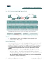
application is active. Likewise, a real-time kernel is memory-resident and provides all the
necessary services for the embedded application. Because it is memory-resident, a real-
time kernel must be as small as possible. Figure 1.1 contains an illustration of a typical
kernel and other RTOS services.
Other RTOS services
Kernel
Figure 1.1: RTOS kernel
Please purchase PDF Split-Merge on www.verypdf.com to remove this watermark.
4 Chapter 1
The operation of an embedded system entails the execution of processes, and tasks or
threads, either in response to external or internal inputs, or in the normal processing
required for that system. The processing of these entities must produce correct results
within specifi ed time constraints.
1.6 Processes, Tasks, and Threads
The term process is an operating system concept that refers to an independent executable
program that has its own memory space. The terms “ process ” and “ program ” are often
used synonymously, but technically a process is more than a program: it includes the
execution environment for the program and handles program bookkeeping details for the
operating system. A process can be launched as a separately loadable program, or it can
be a memory-resident program that is launched by another process. Operating systems
are often capable of running many processes concurrently. Typically, when an operating
system executes a program, it creates a new process for it and maintains within that
process all the bookkeeping information needed. This implies that there is a one-to-one
relationship between the program and the process, i.e., one program, one process.
When a program is divided into several segments that can execute concurrently, we refer
to these segments as threads. A thread is a semi-independent program segment; threads
share the same memory space within a program. The terms “ task ” and “ thread ” are
frequently used interchangeably. However, we will use the term “ thread ” in this book
because it is more descriptive and more accurately refl ects the processing that occurs.
Figure 1.2 contains an illustration of the distinction between processes and threads.
www.newnespress.com
Process
Thread 1
Thread 2
Thread n• • •
ProgramProgram
Figure 1.2: Comparison of processes and threads
Please purchase PDF Split-Merge on www.verypdf.com to remove this watermark.
Embedded and Real-time Systems 5
www.newnespress.com
1.7 Architecture of Real-time Systems
The architecture of a real-time system determines how and when threads are processed.
Two common architectures are the control loop with polling
5
approach and the
preemptive scheduling model. In the control loop with polling approach, the kernel
executes an infi nite loop, which polls the threads in a predetermined pattern. If a thread
needs service, then it is processed. There are several variants to this approach, including
time-slicing
6
to ensure that each thread is guaranteed access to the processor. Figure 1.3
contains an illustration of the control loop with polling approach.
Although the control loop with polling approach is relatively easy to implement, it has
several serious limitations. For example, it wastes much time because the processor polls
threads that do not need servicing, and a thread that needs attention has to wait its turn
until the processor fi nishes polling other threads. Furthermore, this approach makes no
Thread n Thread 1
Thread 2Thread 4
Thread 3
The kernel polls each thread
in sequence to determine
whether or not it needs
the process
Figure 1.3: Control loop with polling approach
5
The control loop with polling approach is sometimes called the super loop approach.
6
Each thread is allocated a predetermined slice of time in which to execute.
Please purchase PDF Split-Merge on www.verypdf.com to remove this watermark.
6 Chapter 1
distinction between the relative importance of the threads, so it is diffi cult to give threads
with critical requirements fast access to the processor.
Another approach that real-time kernels frequently use is preemptive scheduling . In this
approach, threads are assigned priorities and the kernel schedules processor access for
the thread with the highest priority. There are several variants to this approach including
techniques to ensure that threads with lower priorities get some access to the processor.
Figure 1.4 illustrates one possible implementation of this approach. In this example, each
thread is assigned a priority from zero (0) to some upper limit.
7
Assume that priority zero
is the highest priority.
An essential feature in preemptive scheduling schemes is the ability to suspend the
processing of a thread when a thread that has a higher priority is ready for processing.
The process of saving the current information of the suspended thread so that another
thread can execute is called context switching . This process must be fast and reliable
www.newnespress.com
Thread n
PR ϭ 3
Thread 1
PR ϭ 5
Thread 2
PR ϭ 10
Thread 4
PR ϭ 5
Thread 3
PR ϭ 0
The kernel schedules the
thread with the highest priority
(in this case, thread
3 with priority 0) for processor
access
Figure 1.4: Preemptive scheduling method
7
ThreadX provides 1024 distinct priority values, where 0 represents the highest priority.
Please purchase PDF Split-Merge on www.verypdf.com to remove this watermark.
Embedded and Real-time Systems 7
www.newnespress.com
because the suspended thread must be able to resume execution exactly at the point where
it was suspended when it ultimately regains control of the processor.
Embedded systems need to respond to inputs or events accurately and within specifi ed
deadlines. This is accomplished in part by means of an interrupt , which is a signal to the
processor that an event has occurred and that immediate attention may be required. An
interrupt is handled with an interrupt service routine (ISR) , which may activate a thread
with a higher priority than the currently executing thread. In this case, the ISR would
suspend the currently executing thread and permit the higher priority thread to proceed.
Interrupts can be generated from software
8
or by a variety of hardware devices.
1.8 Embedded Systems Development
Embedded applications should be designed and developed using sound software
engineering principles. Because most embedded applications are real-time systems,
one major difference from traditional computer applications is the requirement to
adhere strictly to prescribed time constraints.
9
The requirements and design phases are
performed with the same rigor as any other software application.
Another major consideration in embedded systems development is that the modules (that
is, the threads) are not designed to be executed in a procedural manner, as is the case with
traditional software systems. The threads of an embedded application are designed to
be executed independently of each other or in parallel
10
so this type of system is called
multithreaded .
11
Because of this apparent parallelism, the traditional software-control
structures are not always applicable to embedded systems.
A real-time kernel is used as the engine to drive the embedded application, and the
software design consists of threads to perform specifi c operations, using inter-thread
communication facilities provided by the kernel. Although most embedded systems
development is done in the C (or C ϩϩ ) programming language, some highly critical
portions of the application are often developed in assembly language.
8
Software interrupts are also called traps or exceptions .
9
Some writers liken the study of real-time systems to the science of performance guarantees .
10
In cases where there is only one processor, threads are executed in pseudo-parallel.
11
Multithreading is sometimes called multitasking .
Please purchase PDF Split-Merge on www.verypdf.com to remove this watermark.
8 Chapter 1
1.9 Key Terms and Phrases
www.newnespress.com
control loop with polling priority
determinism real-time kernel
embedded system real-time system
interrupt ROMable
microprocessor RTOS
multithreading scalable
preemptive scheduling Thread
Please purchase PDF Split-Merge on www.verypdf.com to remove this watermark.
First Look at a System Using
an RTOS
CHAPTER 2
2.1 Operating Environment
We will use the Win32 version of ThreadX because it permits developers to develop
prototypes of their applications in the easy-to-use and prevalent Windows programming
environment. We achieve complete ThreadX simulation by using Win32 calls. The
ThreadX-specifi c application code developed in this environment will execute in an
identical fashion on the eventual target hardware. Thus, ThreadX simulation allows real
software development to start well before the actual target hardware is available. We will
use Microsoft Visual C/C ϩϩ Tools to compile all the embedded systems in this book.
2.2 Installation of the ThreadX Demonstration System
There is a demonstration version of ThreadX on the CD included with this book. View
the Readme fi le for information about installing and using this demonstration system.
2.3 Sample System with Two Threads
The fi rst step in mastering the use of ThreadX is to understand the nature and behavior
of threads. We will achieve this purpose by performing the following operations in this
sample system: create several threads, assign several activities to each thread, and compel
the threads to cooperate in the execution of their activities. A mutex will be used to
coordinate the thread activities, and a memory byte pool will be used to create stacks for
the threads. (Mutexes and stacks are described in more detail later.)
www.newnespress.com
Please purchase PDF Split-Merge on www.verypdf.com to remove this watermark.
10 Chapter 2
The fi rst two components that we create are two threads named Speedy_Thread and
Slow_Thread. Speedy_Thread will have a higher priority than Slow_Thread and will
generally fi nish its activities more quickly. ThreadX uses a preemptive scheduling
algorithm, which means that threads with higher priorities generally have the ability to
preempt the execution of threads with lower priorities. This feature may help Speedy_
Thread to complete its activities more quickly than Slow_Thread. Figure 2.1 contains an
illustration of the components that we will use in the sample system.
In order to create the threads, you need to assign each of them a stack : a place where
the thread can store information, such as return addresses and local variables, when it is
preempted. Each stack requires a block of contiguous bytes. You will allocate these bytes
from a memory byte pool, which you will also create. The memory byte pool could also
be used for other ThreadX objects, but we will restrict its usage to the two threads in this
system. There are other methods by which we could assign memory space for a stack,
including use of an array and a memory block pool (to be discussed later). We choose to
use the memory byte pool in this sample system only because of its inherent simplicity.
We will use a ThreadX object called a mutex in this sample system to illustrate the
concept of mutual exclusion. Each of the two threads has two sections of code known as
critical sections . Very generally, a critical section is one that imposes certain constraints
on thread execution. In the context of this example, the constraint is that when a thread
is executing a critical section, it must not be preempted by any other thread executing a
critical section — no two threads can be in their respective critical sections at the same
www.newnespress.com
Speedy_Thread
my_byte_pool
my_mutex
Slow_Thread
Figure 2.1: Components of the sample system
Please purchase PDF Split-Merge on www.verypdf.com to remove this watermark.
First Look at a System Using an RTOS 1 1
time. A critical section typically contains shared resources,
1
so there is the potential for
system failure or unpredictable behavior when more than one thread is in a critical section.
A mutex is an object that acts like a token or gatekeeper. To gain access to a critical
section, a thread must acquire “ ownership ” of the mutex, and only one thread can own
a given mutex at the same time. We will use this property to provide inter-thread mutual
exclusion protection. For example, if Slow_Thread owns the mutex, then Speedy_Thread
must wait to enter a critical section until Slow_Thread gives up ownership of the mutex,
even though Speedy_Thread has a higher priority. Once a thread acquires ownership of a
mutex, it will retain ownership until it voluntarily gives up that mutex. In other words, no
thread can preempt a mutex owned by another thread regardless of either thread’s priority.
This is an important feature that provides inter-thread mutual exclusion.
Each of the two threads in the sample system has four activities that will be executed
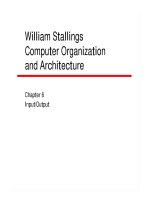
repeatedly. Figure 2.2 contains an illustration of the activities for the Speedy_Thread.
Activities 2 and 4 appear in shaded boxes that represent critical sections for that thread.
Similarly, Figure 2.3 contains an illustration of the activities for the Slow_Thread. Note
that Speedy_Thread has a priority of 5, which is higher than the priority of 15 that is
assigned to the Slow_Thread.
Activity 1
Sleep 2 ticks
Activity 3
Sleep 4 ticks
Activity 2
Get and keep mutex
for 5 ticks
Activity 4
Get and keep mutex
for 3 ticks
Figure 2.2: Activities of the Speedy_Thread (priority ϭ 5)
Activity 6
Sleep 8 ticks
Activity 8
Sleep 9 ticks
Activity 5
Get and keep mutex
for 12 ticks
Activity 7
Get and keep mutex
for 11 ticks
Figure 2.3: Activities of the Slow_Thread (priority ϭ 15)
1
Or, it contains code that accesses shared resources.
www.newnespress.com
Please purchase PDF Split-Merge on www.verypdf.com to remove this watermark.
12 Chapter 2
2.4 Creating the ThreadX Objects
Program listing 02_sample_system.c is located at the end of this chapter and on the
attached CD. It contains the complete source code for our sample system. Detailed
discussion of the specifi cs of this listing is included in later chapters to provide a
highlight of the essential portions of the system. Figure 2.4 contains a summary of the
main features of the source code listing.
The
main() portion of the basic structure contains exactly one executable statement, as
follows:
tx_kernel_enter();
The above entry function turns over control to ThreadX (and does not return!). ThreadX
performs initialization of various internal data structures and then processes the
application defi nitions and the thread entry defi nitions. ThreadX then begins scheduling
and executing application threads. The purpose of the
tx_application_defi ne function in our
sample system is to defi ne all the ThreadX components that will be used. For example,
we need to defi ne a memory byte pool, two threads, and one mutex. We also need to
allocate memory from the byte pool for use as thread stacks. The purpose of the thread
entry functions section is to prescribe the behavior of the two threads in the system.
We will consider only one of the thread entry functions in this discussion because both
entry functions are similar. Figure 2.5 contains a listing of the entry function for the
Speedy_Thread.
Recall that activities 2 and 4 are the critical sections of Speedy_Thread. Speedy_Thread
seeks to obtain ownership of the mutex with the following statement:
tx_mutex_get( & my_mutex, TX_WAIT_FOREVER);
www.newnespress.com
Comments, #include directives,
declarations, definitions, prototypes
main()
tx_application_define function
Thread entry functions
Figure 2.4: Basic structure of sample system
Please purchase PDF Split-Merge on www.verypdf.com to remove this watermark.
First Look at a System Using an RTOS 1 3
If Slow_Thread already owns the mutex, then Speedy_Thread will “ wait forever ” for its
turn to obtain ownership. When Speedy_Thread completes a critical section, it gives up
ownership of the mutex with the following statement:
tx_mutex_put( & my_mutex);
When this statement is executed, Speedy_Thread relinquishes ownership of the mutex, so
it is once again available. If Slow_Thread is waiting for the mutex, it will then have the
opportunity to acquire it.
/* Entry function definition of the "Speedy_Thread"
which has a higher priority than the “Slow_Thread” */
void Speedy_Thread_entry(ULONG thread_input)
{
UINT status;
ULONG current_time;
While (1)
{
/* Activity 1: 2 timer-ticks */
tx_thread_sleep(2);
/* Get the mutex with suspension */
tx_mutex_get(&my_mutex, TX_WAIT_FOREVER);
/* Activity 2: 5 timer-ticks */ *** critical section *** */
tx_thread_sleep(5);
/* Release the mutex */
tx_mutex_put(&my_mutex);
/* Activity 3: 4 timer-ticks */
tx_thread_sleep(4);
/* Get the mutex with suspension */
tx_mutex_get(&my_mutex, TX_WAIT_FOREVER);
/* Activity 4: 3 timer-ticks *** critical section *** */
tx_thread_sleep(3);
/* Release the mutex */
tx_mutex_put(&my_mutex);
current_time = tx_time_get();
printf("Current Time: %5lu Speedy_Thread finished cycle \n",
current_time);
}
}
Figure 2.5: Entry function defi nition for the Speedy_Thread
www.newnespress.com
Please purchase PDF Split-Merge on www.verypdf.com to remove this watermark.
14 Chapter 2
www.newnespress.com
The entry function for Speedy_Thread concludes by getting the current system time and
displaying that time along with a message that Speedy_Thread has fi nished its current
cycle of activities.
2.5 Compiling and Executing the Sample System
Compile and execute the sample system contained in 02_sample_system.c that is located
on the attached CD. A complete listing appears in a section at the end of this chapter.
2.6 Analysis of the System and the Resulting Output
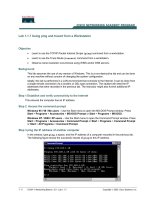
Figure 2.6 contains output produced by executing the sample system. Your output should
be similar, but not necessarily identical.
The minimum amount of time in which Speedy_Thread can complete its cycle of
activities is 14 timer-ticks. By contrast, the Slow_Thread requires at least 40 timer-ticks
to complete one cycle of its activities. However, the critical sections of the Slow_Thread
will cause delays for the Speedy_Thread. Consider the sample output in Figure 2.6 where
the Speedy_Thread fi nishes its fi rst cycle at time 34, meaning that it encountered a delay
of 20 timer-ticks because of the Slow_Thread. The Speedy_Thread completes subsequent
cycles in a more timely fashion but it will always spend a lot of time waiting for the
Slow_Thread to complete its critical section.
2.7 Listing of 02_sample_system.c
The sample system named 02_sample_system.c is located on the attached CD. The
complete listing appears below; line numbers have been added for easy reference.
Current Time: 34 Speedy_Thread finished cycle
Current Time: 40 Slow_Thread finished cycle
Current Time: 56 Speedy_Thread finished cycle
Current Time: 77 Speedy_Thread finished cycle
Current Time: 83 Slow_Thread finished cycle
Current Time: 99 Speedy_Thread finished cycle
Current Time: 120 Speedy_Thread finished cycle
Current Time: 126 Slow_Thread finished cycle
Current Time: 142 Speedy_Thread finished cycle
Current Time: 163 Speedy
_
Thread finished cycle
Figure 2.6: Output produced by sample system
Please purchase PDF Split-Merge on www.verypdf.com to remove this watermark.
First Look at a System Using an RTOS 1 5
www.newnespress.com
001 /* 02_sample_system.c
002
003 Create two threads, one byte pool, and one mutex.
004 The threads cooperate with each other via the mutex. */
005
006
007 /****************************************************/
008 /* Declarations, Defi nitions, and Prototypes */
009 /****************************************************/
010
011 #include “tx_api.h”
012 #include Ͻ stdio.h Ͼ
013
014 #defi ne DEMO_STACK_SIZE 1024
015 #defi ne DEMO_BYTE_POOL_SIZE 9120
016
017
018 /* Defi ne the ThreadX object control blocks … */
019
020 TX_THREAD Speedy_Thread;
021 TX_THREAD Slow_Thread;
022
023 TX_MUTEX my_mutex;
024
025 TX_BYTE_POOL my_byte_pool;
026
027
028 /* Defi ne thread prototypes. */
029
030 void Speedy_Thread_entry(ULONG thread_input);
031 void Slow_Thread_entry(ULONG thread_input);
032
033
034 /****************************************************/
035 /* Main Entry Point */
036 /****************************************************/
037
038 /* Defi ne main entry point. */
039
040 int main()
041 {
Please purchase PDF Split-Merge on www.verypdf.com to remove this watermark.