Chapter 3: The Processor pdf
Bạn đang xem bản rút gọn của tài liệu. Xem và tải ngay bản đầy đủ của tài liệu tại đây (7.67 MB, 134 trang )
2009
dce
KIẾN TRÚC MÁY TÍNH
CS2009
BK
TP.HCM
Khoa Khoa học và Kỹ thuật Máy tính
BM Kỹ thuật Máy tính
Võ Tấn Phương
/>~
vtphuong/KTMT
©2009, CE Department
vtphuong/KTMT
2009
dce
Chapter 3
The Processor
Adapted
from
Computer
Organization
and
Adapted
from
Computer
Organization
and
Design, 4
th
Edition, Patterson & Hennessy, ©
2008
©2009, CE Department©2009, CE Department
2
11/17/2009
2009
dce
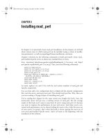
The Five classic Components of a Computer
©2009, CE Department©2009, CE Department
3
11/17/2009
2009
dce
Introduction
• CPU performance factors
– Instruction count
• Determined by ISA and compiler
– CPI and Cycle time
•
Determined by CPU hardware
Determined
by
CPU
hardware
• We will examine two MIPS implementations
– A simplified version
– A more realistic pipelined version
• Simple subset, shows most aspects
Mf
l
–
M
emory re
f
erence:
l
w, sw
– Arithmetic/logical: add, sub, and, or, slt
–
Control transfer:
beq
,
j
©2009, CE Department
Control
transfer:
beq
,
j
2009
dce
Instruction Execution
•PC → instruction memory, fetch instruction
•
Register numbers
→
register file read registers
Register
numbers
→
register
file
,
read
registers
• Depending on instruction class
–
Use ALU to calculate
Use
ALU
to
calculate
• Arithmetic result
• Memory address for load/store
• Branch target address
– Access data memory for load/store
–
PC
←
target address or PC + 4
–
PC
←
target
address
or
PC
+
4
©2009, CE Department
2009
dce
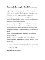
CPU Overview
©2009, CE Department
2009
dce
Multiplexers
• Can’t just join
wires together
wires
together
– Use multiplexers
©2009, CE Department
2009
dce
Control
©2009, CE Department
2009
dce
Logic Design Basics
• Information encoded in binary
Low voltage = 0 High voltage = 1
–
Low
voltage
=
0
,
High
voltage
=
1
– One wire per bit
Multi
bit data encoded on multi
wire buses
–
Multi
-
bit
data
encoded
on
multi
-
wire
buses
• Combinational element
–
Operate on data
– Output is a function of input
• State (sequential) elements
–
Store information
©2009, CE Department
2009
dce
Combinational Elements
• AND-gate
A
Y
+
• Adder
– Y = A & B
A
Y
B
Y
+
– Y = A + B
B
Y
•
Multiplexer
• Arithmetic/Logic Unit
•
Multiplexer
– Y = S ? I1 : I0
A
– Y = F(A, B)
I0
I1
Y
M
u
x
B
Y
ALU
©2009, CE Department
S
F
2009
dce
Sequential Elements
• Register: stores data in a circuit
Uses a clock signal to determine when to
–
Uses
a
clock
signal
to
determine
when
to
update the stored value
–
Edge
-
triggered: update when Clk changes
–
Edge
-
triggered:
update
when
Clk
changes
from 0 to 1
DQ
Clk
D
Clk
D
Q
©2009, CE Department
2009
dce
Sequential Elements
• Register with write control
Only updates on clock edge when write
–
Only
updates
on
clock
edge
when
write
control input is 1
–
Used when stored value is required later
–
Used
when
stored
value
is
required
later
Clk
DQ
Write
Clk
Clk
Write
D
Q
©2009, CE Department
2009
dce
Clocking Methodology
• Combinational logic transforms data
du
rin
g
c
l
oc
k
cyc
l
es
du g c oc cyc es
– Between clock edges
–
In
p
ut from state elements
,
out
p
ut to state
p,p
element
– Longest delay determines clock period
©2009, CE Department
2009
dce
Building a Datapath
• Datapath
Elements that process data and addresses
–
Elements
that
process
data
and
addresses
in the CPU
•
Registers, ALUs, mux
’
s, memories, …
Registers,
ALUs,
mux s,
memories,
…
• We will build a MIPS datapath
incrementally
incrementally
– Refining the overview design
©2009, CE Department
2009
dce
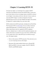
Instruction Fetch
32-bit
register
Increment by
4 for next
instruction
register
©2009, CE Department
2009
dce
Review Instruction Formats
©2009, CE Department
16
2009
dce
R-Format Instructions
• Read two register operands
Perform arithmetic/logical operation
•
Perform
arithmetic/logical
operation
• Write register result
©2009, CE Department
2009
dce
Load/Store Instructions
• Read register operands
• Calculate address usin
g
16-bit offset
g
– Use ALU, but sign-extend offset
• Load: Read memory and update register
• Store: Write register value to memory
©2009, CE Department
2009
dce
Branch Instructions
• Read register operands
Compare operands
•
Compare
operands
– Use ALU, subtract and check Zero output
• Calculate target address
– Sign-extend displacement
– Shift left 2 places (word displacement)
– Add to PC + 4
• Already calculated by instruction fetch
©2009, CE Department
2009
dce
Branch Instructions
Just
re
routes
re
-
routes
wires
Sign
-
bit wire
©2009, CE Department
Sign
bit
wire
replicated
2009
dce
Composing the Elements
• First-cut data path does an instruction in
one clock cycle
one
clock
cycle
– Each datapath element can only do one
function at a time
function
at
a
time
– Hence, we need separate instruction and data
memories
memories
• Use multiplexers where alternate data
sources are used for different instructions
sources
are
used
for
different
instructions
©2009, CE Department
2009
dce
R-Type/Load/Store Datapath
©2009, CE Department
2009
dce
Full Datapath
©2009, CE Department
2009
dce
ALU Control
• ALU used for
Load/Store: F = add
–
Load/Store:
F
=
add
– Branch: F = subtract
R
type: F depends on funct field
–
R
-
type:
F
depends
on
funct
field
ALU control Function
0000 AND
0001 OR
0010 add
0110 subtract
0111 set-on-less-than
1100
NOR
©2009, CE Department
1100
NOR
2009
dce
ALU Control
• Assume 2-bit ALUOp derived from opcode
Combinational logic derives ALU control
–
Combinational
logic
derives
ALU
control
opcode ALUOp Operation funct ALU function ALU control
lw 00 load word XXXXXX add 0010
sw 00 store word XXXXXX add 0010
be
q
01 branch e
q
ual XXXXXX subtract 0110
q
q
R-type 10 add 100000 add 0010
subtract 100010 subtract 0110
AND
100100
AND
0000
AND
100100
AND
0000
OR 100101 OR 0001
set-on-less-than 101010 set-on-less-than 0111
©2009, CE Department