Gear Noise and Vibration P2 ppsx
Bạn đang xem bản rút gọn của tài liệu. Xem và tải ngay bản đầy đủ của tài liệu tại đây (892.48 KB, 20 trang )
10
Chapter
1
can be
done
on a
test
rig out in the
main works
or
sometimes even
on the
equipment
while running normally.
However,
the
basic idea
is
that pitch, profile
and
helix errors
may
combine with tooth bending, gear body distortions
and
whole gear body
deflections
to
give
an
overall relative deflection
(from
smooth running)
at the
meshpoint
between
the
gears.
It is
also
difficult
to
convince gear engineers
that there
is a
very
big
difference
between roll (double
flank)
checking, which
is
extremely cheap
and
easy,
and
T.E. (single
flank)
checking since they give
rather
similar looking
results.
Unfortunately,
there
are a
large
number
of
important gear errors which
are
missed completely
by
roll checking
so
this
method should
be
discouraged except
for
routine control
of
backlash.
The
problems with double
flank
measurement arise
from the
basic averaging
effect
that occurs.
Any
production
process
or
axis error
in
transfer
from
machine
to
machine
may
produce errors which give
+ve
errors
on one flank
which
effectively
cancel
-ve
errors
on the
facing
flank. The
resulting
centre
distance variation
is
negligible
but
there
may be
large (cancelling) errors
on
the
drive
and
overrun
flanks.
Shavers
and
certain types
of
gear grinders
are
prone
to
this type
of
fault
which
is
worse with high helix angle
gears.
The
question then arises
as to the
connection between T.E.
and
final
noise.
Few
practising engineers initially believe
the
academics' claim that
noise
is
proportional
to
T.E., although
the
system normally behaves (except
under light load)
as a
linear system.
For any
linear system
the
output should
be
proportional
to
input. Doubling
the
T.E. should give
6dB
increase
in
noise
level
or,
with
a
target reduction
of
lOdB
on
noise,
the
T.E. should
be
reduced
by
VlO,
i.e., roughly
3.
This only applies
at a
single
frequency and
different
frequencies
encounter high
or low
responses
en
route
so a
major
visible
frequency
component
in the
T.E.
may be
minor
in the
final
noise because
it
could
not
find
a
convenient
resonance.
Tests
over
20
years
ago
[7,8]
established
the
link,
and
recent accurate work
by
Palmer
and
Munro
[9] has
confirmed
the
exact relationship
by
direct testing
and
shown
how the
noise
corresponds exactly
to the
T.E.
Since
most companies
flatly
refuse
to
believe that there
is a
direct
link
between noise
and
T.E.,
it is
common
for
companies
to
re-invent
the
wheel
by
testing T.E.
and
cross-checking against
testbed
noise checks. This
is
apparently very wasteful
but has the
great advantage
of
establishing what
T.E. levels
are
permissible
on
production,
as
well
as
giving people
faith
that
the
test
is
relevant.
For
this learning stage
of the
process
it is
simplest
to
borrow
or
hire
a set of
equipment
to
establish relevance before tackling
a
capital
requisition
or to
take
sets
of
gears
for
test
to the
nearest
set of
equipment. Unfortunately, those
few
firms
who
have T.E. equipment usually
use it
very heavily
so it may be
better
to ask a
university
if
equipment
can be
hired. Newcastle [10],
Huddersfield
[11],
and
Cambridge [12]
in the
U.K.,
Causes
of
Noise
11
Ohio State University
[13]
and
other researchers [14,
15,
16]
have developed
their
own
T.E. equipment
and are
usually happy
to
provide
experience
as
well
as a foil
range
of
equipment
and
analysis techniques. Academic equipment
based
on
off-line
analysis
is
often,
however,
not
suited
to
high speeds
or
mass
production.
References
1.
Lemanski,
A. J.,
Gear Design, S.A.E.,
Warrendale
1990.
Ch 3.
2.
Buckingham,
Earle,
Analytical mechanics
of
spur
gears,
Dover,
New
York.
1988.
3.
Harris, S.L.,
'Dynamic
loads
on the
teeth
of
spur
gears.'
Proc.
Inst.
Mech.
Eng.,
Vol
172, 1958,
pp
87-112.
4.
Gregory,
R.W.,
Harris, S.L.
and
Munro,
R.G.,
'Dynamic
behaviour
of
spur
gears.'
Proc.
Inst. Mech.
Eng.,
Vol
178,
1963-64,
Part
I, pp
207-226.
5.
Munro, R.G.,
'The
Effect
of
Geometrical Errors
on the
Transmission
of
Motion
Between
Gears.'
I.
Mech.
E.
Conf. Gearing
in
1970, Sept. 1970,
p
79.
6.
Cremer,
L.,
Heckl,
M., and
Ungar, E.E., Structure-borne sound.
Springer-Verlag,
1973, Berlin.
7.
Kohler, H.K., Pratt,
A.,
Thompson, A.M. Dynamics
and
noise
of
parallel
axis gearing.
Inst.
Mech. Eng. Conf. Gearing
in
1970, Sept,
pp
111-121.
8.
Furley, A.J.D.,
Jeffries,
J.A.
and
Smith, J.D.,
'Drive
Trains
in
Printing
Machines', Inst. Mech. Eng. Conference, Vibrations
in
Rotating
Machinery,
Cambridge, 1980, pp.239-245.
9.
Palmer,
D. and
Munro,
R.G.,
'Measurements
of
transmission error,
vibration
and
noise
in
spur
gears.'
British Gear Association Congress,
1995, Suite
45,
IMEX
Park, Shobnall Rd., Burton
on
Trent.
10.
The
Design Unit,
Stephenson
Building,
Claremont
Rd,
Newcastle upon
TyneNEl
7RU, U.K.
D.A.
Hofrnann.
11.
Dept.
of
Mechanical
Eng.,
Queensgate,
Huddersfield,
HD1
3DH, U.K.
Prof R.G. Munro.
12.
University Eng.
Dept.,
Trumpington
St., Cambridge
CB2
1PZ, U.K.
Dr
J.Derek Smith.
13.
Ohio State Univ., Mech. Eng.
Dept.,
206
West 18
th
Ave., Columbus, Ohio,
43210-1107.
Prof
D.
R.
Houser.
14
INS
A de
Lyon,
Villeurbane,
Cedex, France.
Mr D.
Remond.
15.
University
of New
South Wales, Australia.
Mr
R.B.
Randall.
16.
Tech.
Univ.
of
Ostrava,
CZ - 703 88
Ostrava, Czech Republic.
Mr.
Jiri
Tuma.
Mapping
for
Spur Gears
2.1
Elastic
deflections
of
gears
The
basic geometric theory
for
spur gears assumes
the
"unwrapping
string"
generation
of a
perfect
involute.
We can
then replace
the two
mating
involute
curves with
a
string unwrapping
from one
base circle
and
coiling
onto
the
other base circle
as in
Fig.
2.1.
A
contact between
one
pair
of
mating teeth should then travel along
the
"string,"
the
"pressure
line"
or
"line
of
contact"
until
it
reaches
the tip of
the
driving gear tooth.
To
achieve
a
smooth take-over,
before
one
contact
reaches
the tip
there must
be
another contact coming into action,
one
tooth
space behind.
For the
theoretical ideal
of a
rigid gear
the
only requirement
for
a
smooth take-over
is
that
the
base
pitch,
the
distance between
two
successive teeth along
the
pressure line, should
be
exactly
the
same
for
both
gears.
Unfortunately,
although gear teeth
are
short
and
stubby, they have
elasticity
and
there
are
significant
deflections.
The
deflection between
two
teeth
is
partly
due to
Hertzian contact deflections, which
are
non-linear,
but
mainly
due to
bulk tooth movement because
the
tooth acts
as a
rather short
cantilever with
a
very complex
stress
distribution
and
some rotation occurs
at
the
tooth
root.
A
generally accepted Figure
for the
mesh
stiffness
of
normal
teeth
is 1.4 x 10
N/m/m
or 2 x 10
IbFin/in,
a
Figure used
by
Gregory,
Harris
and
Munro
[1] in the
late 1950s
but one
which
has
stood
the
test
of
time.
As a
rough rule
of
thumb
we can
load gears
to
100N
per mm of
face
width
per mm
module
so a 4 mm
module gear
25 mm
wide might
be
loaded
to
10,OOON
(1
ton). This load
infers
a
deflection
of the
order
of
400/1.4
x
10
7
m
or
28.6
pm
(1.1
mil).
Experimental measurement
of
this rather high
stiffness
has
proved
extremely
difficult
both statically
and
dynamically even with spur gears
so
that
we are
mainly dependent
on
finite
element
stressing
software
packages
to
give
an
answer. There
is a
significant
effect
at the
ends
of
gears since
the
ability
to
expand axially reduces
the
effective
Young's modulus
and
high
angle
helical
gears
have reduced
contact
support
at one end and
additional
buttressing
at the
other end.
13
14
Chapter
2
base
pilph
pinion
x
X
base
pitctf
wheel
Fig 2.1
Handover
of
contact
betweeen
successive teeth.
Different
manufacturing methods produce
different
root shapes
and
affect
stiffness,
but the
main variations arise
from
variation
of
pressure angle
or
undercutting and,
to a
lesser extent,
from low
tooth numbers.
The
stiffness
of
each tooth varies considerably
from
root
to
tip,
but
with
two
teeth
the
effects
mainly cancel.
The
highest combined
stiffness
occurs with contact
at the
pitch points
and the
stiffness
decreases
about
30%
toward
the
limits
of
travel
but the
decrease
is
highly
dependent
on the
contact
ratio
and
gear
details.
In
practice
it is
unusual
for the
applied load
to be
completely even
across
the
face
width
as
this implies that helix
and
alignment accuracies,
and
gear body deflections, must
sum to
less
than
a few
fim.
As a
result,
we
have
Harris Mapping
for
Spur
Gears
15
to
allow
for
typically
up to
100% overload
and
deflection
at
either
end of the
tooth,
or in the
middle
if
crowned,
so
deflections
can be
large.
Using
the
rule
of
thumb that conventional surface-hardened teeth
may be
loaded
to
100
N/mm
facewidth/mm
module,
the
above
4mm
module gear
(6 DP)
loaded
to
400
N/mm would deflect 400/14, i.e.,
28
urn,
nominally but, allowing
for
load
concentrations, this could
rise
to 50
um
(2
mil).
2.2
Reasons
for tip
relief
Since there
is
deflection
of the
mating pair
of
teeth under load,
it is
not
possible
to
have
the
next
tip
enter contact
in the
pure involute position
because there would
be
sudden interference corresponding
to the
elastic
deflection
and the
corner
of the
tooth
tip
would gouge into
the
mating surface.
Manufacturing
errors
can add to
this
effect
so
that
it is
necessary
to
relieve
the
tooth
tip
(Fig.
2.2)
to
ensure that
the
corner does
not dig in.
Correspondingly,
at the end of the
contact,
the
(other) tooth
tip is
relieved
to
give
a
gradual removal
of
force.
High loads
on the
unsupported corner
of a
tooth
tip
would give high
stresses
and
rapid
failure,
especially with
case-
hardened gears which might spall (crack their
case).
In
addition
a
sharp
corner plays havoc with
the oil film
locally
as the oil
squeezes
out too
easily
allowing
metal
to
metal contact
and
accelerated failure.
Tip
relief design
was
traditionally
a
black
art but can be
determined logically.
>tip
/
relief
involute
tip
relieved
correct
pure
involute
(a)
tooth
root
(b)
Fig 2.2
Picture
of tip
relief showing deviation
from an
involute
in (a) and
typical tooth shape (b).
16
Chapter
2
The
amount
of
"tip
relief
needed
in the
example above
can be
estimated
by
adding
the
worst
case
elastic deflection,
for
example,
28.6um
+
70% (to
allow
for
misalignment),
to the
possible base (adjacent) pitch errors
of
3
um
on
each gear
and to the
possible
profile
errors
of 3
um
on
each gear.
The
total
tip
relief needed
is
then
61
jim
(2.5 mil).
There
can be
some extra
tip
relief correction required
if
there
is a
large temperature
differential
between
two
mating
gears,
as one
base pitch grows more than
the
other
due to
thermal
expansion,
but the
effect
is
usually very small
[2].
This
"tip
relief
can be
achieved
by
removing metal
from the tip or
the
root
of the
teeth
or from
both. There
are two
main schools
of
thought.
The
traditional approach
was to
give
tip and
root relief,
as
indicated
in
Fig
2.3, with
a
rather arbitrary division between
the two and
with
the tip and
root
relief
meeting roughly
at the
pitch point.
The
actual shape
of the
relief,
as a
function
of
roll
angle, which
is
directly proportional
to
roll distance, tends
to
be
almost parabolic.
There
are two
problems with this approach.
It is not
immediately
clear where
the tip of the
mating tooth will meet
the
lower part
of the
working
flank
so it is
more
difficult
to
work
out how
much
the
effective
root relief
is at
the
point where
the
mating
tip
meets
the
flank.
Rather more important
is the
fact
that this parabolic shape
of
relief
is not
desirable
from
either noise
aspects
and for
helical
gears
is
undesirable
from
stressing
aspects.
tip
relief
profile
metal
involute
air
root
relief
tip
pitch line
end of
active profile
Fig
2.3 Tip and
root relief applied
on a
gear.
Harris Mapping
for
Spur Gears
17
In
practice,
we
usually wish
to
have relief varying linearly with roll
angle, starting
at a
point
on the flank
well above
the
pitch
point
so
that there
is
a
significant part
of a
tooth pair meshing cycle where
two
"correct"
involutes
are
meeting.
When
discussing
profile
corrections there
are
initially
two
uncertainties about
the
specifications.
The first is
whether
the
relief quoted
is
in
the
tangential direction
or
whether
in the
direction
of the
line
of
action.
As
the
difference
is
normally
only
6% on
standard
gears
it is not
important
but
most
traditional profile measuring machines measure normal
to the
involute
(i.e.,
in the
direction
of the
line
of
action)
and it is the
movement
or
error
in
this direction that gives
the
vibration excitation
so we
usually
specify
this.
When
using
a 3-D
coordinate measuring machine
it is
again better
to
work
in
the
direction
of the
line
of
action.
The
other possible uncertainty
is
determining
the
position
of a
point
up
the
tooth
flank. The
obvious
choices
of
distance
from
root
or tip are
irrelevant
as the
profile
ends
are not
accurate.
Fig
2.4
Unwrapping string model.
18
Chapter
2
Specifying
actual radius
is of
little help
in
locating
the
correct
points
and
referencing them
to
gear rotation. What
is
done
in
practice
is to
work
in
terms
of
roll distance.
See
Fig. 2.4.
As the
gear rotates
and the
"unwrapping
string" leaves
one
gear base circle
and
transfers
to the
other
there
is a
linear relationship between rotation
and the
distance that
the
common
point
of
contact moves along
the
line
of
action. Roll distance
is
simply
roll angle
in
radians times base circle radius.
We
measure
and
specify
position
in the
tooth mesh cycle
by
giving
the
distance that
the
point
of
contact
has
travelled. Tooth
flank
starting
and finishing
points
are
unclear
so
design works
in
roll
distance measured
from the
pitch point.
10
degree angular
equal
roll
distances
Fig 2.5
Effect
of
equal steps
of
roll
on
involute.
Harris Mapping
for
Spur Gears
19
There
is not a
linear connection between roll distance
and
distance
up
the flank as can be
seen
from
Fig.
2.5
which shows
the
"string" unwrapped
at
equal angular intervals
and so
equal distances along
the
line
of
action.
Up
the
flank the
distance intervals (between arrow tips) steadily
increase.
When
giving experimental measurements
of
profile
or of the
design
on
a
single gear
of a
pair
it is
usual
to
show
the
reliefs
relative
to a
perfect
involute which
is a
straight vertical line
up the
page. Roll distance
is
vertical
and
the
reliefs
(to
large scale)
are
shown horizontally
as in
Fig. 2.3. However
when
we are
looking
at the
meshing
of a
pair
of
teeth
the
picture
is
turned
on
its
side
as in
Fig.
2.6 so
that roll distances
are
horizontal
and
reliefs
are
vertical. There
can be
problems locating exactly where
on an
experimental
profile
measurement
the
pitch point occurs
as it can
only
be
located
by an
accurate knowledge
of the
pitch radius
and
this depends
on the
centre
distance
at
which
the
pair
of
gears will run.
The
main choice
in
profile
design
is
between giving both
tip and
root
relief
on the
pinion
so
that
the
wheel
(or
annulus)
stays pure involute
for
easy
production
or
giving
tip
relief,
but no
root relief,
on
both, which
is
easier
to
assess
and
control. This choice
can be
controlled
by
production constraints
of
availability
of
suitable gear machines
and
cutters.
In
this book
it is
assumed
that
tip
relief
is
given
on
both gears
but
there
is no
root relief
to
complicate
the
geometry.
A
very special case
arises
for
very large slow
gears
which have been
in
service
for a
while
so
that both pinion
and
wheel have worn away
from
their original (involute)
profile.
The
most economical repair
is
then
to
leave
the
wheel
as it is and
adjust
the
profile
of the
pinion
to
suit
the now
incorrect
wheel.
2.3
Unloaded T.E.
for
spur
gears
Fig.
2.6 (a)
shows
diagrammatically
what happens when
we
take
two
mating spur gear teeth, each with
tip
relief extending
a
third
of the way
down
(but
no
root relief),
and
mesh them.
All
distances along
the
profile
are
in
terms
of
roll distance,
not
actual distance,
and so are
proportional
to
gear
rotation
(multiplied
by
base circle radius).
The
horizontal line
represents
the
pure involute
and the two
tooth
profiles,
shown slightly apart
for
clarity,
follow
the
involute
profile
to
above
their pitch line where they
are
relieved.
In
this case
the tip
reliefs
are
linear,
as is
modern custom.
The
combination
of two
teeth with perfect involutes
in
the
centre
is to
give zero T.E.
for
this part
of the
mesh. Where there
is tip
relief
it is
irrelevant
which
gear
has it as
either gives
a
drop
in the
T.E. trace
for
the
combination.
20
Chapter
2
pinion
tip
^
T\\\\\\\x\NX\x^^^^^
relief
roll
roll_
distance"
root
tS
P
pitch
(a)
P°
int
I
pure
involute
or
zero
T.E.
I
positive
metal
I.E.
4
^^
negative metal
(b)
Fig 2.6
Effects
of
mating
two
spur gear profiles, each with
tip
relief.
T.E.
traces
are
conventionally drawn with positive metal giving
an
upward movement
but
when testing experimentally
the
results
can
correspond
to
positive metal either
way so it is
advisable
to
check polarity.
In the
metrology
lab
this
can
simplest
be
done
by
passing
a
piece
of
paper
or
hair
though
the
mesh.
The
combined
effect
of one
pair
of
teeth meshing under
no
load
would
be to
give
a
T.E.
of the
shape shown
in
Fig.
2.6(b)
with about
one
third
of the
total span
following
the
involute
for
both profiles
and
generating
no
error.
The tip
reliefs
then give
a
drop (negative metal)
at
both ends.
The
same
effect
is
obtained
if the
relief
is
solely
on the
pinion
at tip and
root.
However,
the
geometry
is
more complex
at the
root
as the
mating
tip
does
not
penetrate
to the
bottom
of the
machined
flank.
Putting several pairs
of
teeth
in
mesh
in
succession gives
the
effect
shown
in
Fig.
2.7(a).
If
there
are no
pitch
or
profile
errors
and no
load
applied
so no
elastic deflections,
the
central involute sections
will
be at the
same level
(of
"zero" T.E.)
and
part
way
down
the tip
relief there
will
be a
handover
to the
next contacting pair
of
teeth.
One
base pitch
is
then
the
distance
from
handover
to
handover. When
we
measure
T.E.
under
no-load
conditions
we
cannot
see the
parts shown
dashed
since handover
to the
next
pair
of
teeth
has
occurred.
Harris
Mapping
for
Spur Gears
21
pure
involute
or
zero
T.E.
roll
distance
one
base
pitch
Fig
2.7(a)
Effect
on
T.E.
of
handover
to
successive teeth when there
are no
elastic deflections.
pitch
error
roll
distance
zero
T.E.
base
pitch
Fig
2.7(b)
Effect
of
pitch error
on
position
of
handover
and
T.E.
Fig.
2.7(b) shows
the
effect
of a
pitch error which will
not
only give
a
raised section
but
will alter
the
position
at
which
the
handover
from one
pair
to the
next
occurs,
2.4
Effect
of
load
on
T.E.
We
wish
to
predict
the
T.E. under load
as
this
is the
excitation which
will
determine
the
vibration levels
in
operation.
As
soon
as
load
is
applied there
are two
regimes,
one
around
the
pitch
point where only
one
pair
of
teeth
are in
contact
and one
near
the
handover points where there
are two
pairs
in
contact, sharing
the
load
but
not,
in
general,
equally.
The
total load remains constant
so, as we are
taking
the
simplifying
assumption that
stiffness
is
constant,
the
combined deflection
of
the two
pairs
in
contact must equal
the
deflection when just
one
pair
is in
contact.
In
particular, exactly
at the
changeover
points,
the
loads
and
deflections
are
equal
if
there
are no
pitch
errors
so
each contact deflection
should
be
half
the
"single
pair"
value.
22
Chapter
2
pitch
point
\
iefl
z_
I o
X
changeover
point
changeover
point
one
base
pitch
roll
distance
contact
ratio times base
pitch
Fig 2.8
Harris
map of
interaction
of
elastic deflections
and
long
tip
relief.
This explanation
of the
handover
process
was
developed
by
Harris
[3] and the
diagrams
of the
effects
of
varying load
are
termed "Harris
maps."
Fig.
2.8
shows
the
effect.
The top
curve
(n) is the
T.E. under
no
load
and
then
as
load
is
applied
the
double contact regime steadily expands around
the
changeover point. Curve
(h) is the
curve
for
half
"design"
load.
At
a
particular "design
load"
the
effects
of tip
relief
are
exactly cancelled
by the
elastic deflections (curve
d) so
there
is no
T.E. There
is a
downward
deflection
(defl)
away
from the
"rigid pure involute" position but,
as the sum
of tip
relief
and
deflection
is
constant,
it
does
not
cause vibration.
Above
the
"design"
load
the
single contact deflections
are
greater
than
the
combined double contact plus
tip
relief deflections.
The
result
is as
shown
by
curve
(o)
with
a
"positive metal"
effect
at
changeover. Varying
stiffness
throughout
the
mesh alters
the
effects
slightly,
but the
principle
remains.
In
this approach
it
should
be
emphasised that "design" load
is the
load
at
which minimum T.E.
is
required,
not the
maximum applied load
which
may be
much greater.
Since
the
eventual objective
is to
achieve
minimum
T.E. when
the
drive
is
running under load, there
will
normally
be a
desired design T.E.
under
(test)
no-load.
This leads
to the
curious phraseology
of the
"error
in the
transmission
error,"
meaning
the
change
from the
desired
no-load
T.E. which
has
been estimated
to
give
zero-loaded
T.E.
Harris Mapping
for
Spur Gears
23
2.5
Long,
short,
or
intermediate relief
In
1970, Neimann
in
Germany
[4] and
Munro
in the
U.K.
introduced
and
developed
the
ideas
of
"long"
and
"short"
relief designs
for
the two
extreme load
cases
where
the
"design" load
is
full
load
or is
zero load.
Fig.
2.8
shows
the
variation
of
T.E. with load
for a
"long
relief
design"
which
is
aimed
at
producing minimum noise
in the
"design
load"
condition.
Specifying
the tip
relief
profile
begins with determining
the tip
relief
at the
extreme
tip
points
T,
making
the
normal assumptions about overload
due to
misalignment
and
manufacturing
errors.
The
necessary relief
at the
crossover
points
C
(where contact hands over
to the
next pair
of
teeth
at
no-load)
is
half
the
mean
elastic
deflection
and
here
we do not
take manufacturing errors into
account. Typically
the
relief
at T may be 3 to 4
times that
at C. The
crossover points
C are
spaced
one
base pitch apart
and the tip
points
T are
spaced apart
the
contact ratio times
a
base
pitch.
It is, of
course, simplest
if
the tip
reliefs (which should
be
equal)
are
symmetrical.
The
start
of
(linear)
tip
relief
is
then
found
by
extending
TC
backwards till
it
meets
the
pure
involute
at the
point
S.
An
alternative requirement
is to
have
a
design which
is
quiet
at no
load
or a
very light load since this
is
likely
to
occur
for the final
drive
motorway
cruising condition
or
when industrial machinery
is
running light,
as
often
happens.
combined
IE of
one
pairof
teeth
involute
/
n
h
I
[ft
pitch
I /
point
|
T/
changeover
point
one
base
pitch
11
•
,,
,.
.
^
I
contact
ratio
times base
pitch
roll
distance
r
Fig
2.9
Harris
map of
deflections with
a
"short"
tip
relief design.
24
Chapter
2
The
"design" condition
is
zero load
so we
require
"short
relief
as
shown
in
Fig. 2.9, which shows
the
variation
of
T.E. with load
for
"short"
tip
relief.
The
pure involute extends
for the
whole
of a
base pitch
so
there
is no
tip
relief encountered
at all at
light load (n).
The tip
relief
at T
must,
however,
still
allow
for all
deflections
and
errors.
As
load
is
applied
we are
then exceeding
"design"
load
of
zero
and
there
will
be
considerable T.E. with high sections
at the
changeover points.
Curve "ft"
is the
full
torque curve where there
is a
section
at
changeover with
double
contact
and
hence half
the
deflection
(defl)
from the
pure involute that
occurs near
the
pitch points. Palmer
and
Munro
[5]
succeeded
in
getting very
good agreement between predicted
and
measured T.E. under varying load
in a
test
rig to
confirm these predictions.
Care must
be
taken when discussing
"design
load"
in
gearing
to
define
exactly what
is
meant because
one
designer
may be
thinking purely
in
terms
of
strength
so his
"design"
load
will
be the
maximum that
the
drive
can
take.
If,
however, noise
is the
critical factor,
"design
load"
may
refer
to the
condition
where noise
has to be a
minimum
and may be
only
10% of the
permitted
maximum
load.
If the
requirement
is for
minimum noise
at, for
instance, half load, then
the
relief should correspondingly
be a
"medium"
relief.
The
short
or
long descriptions refer
to the
starting position
of the
relief,
but the
amount
of
relief
at the tip of
each tooth remains constant.
Pure involute
Expected single pair
deflection
under
full
load
Previous
pair
Tip
Crossover
position
Fig
2.10 Tooth relief shapes near crossover
for
low, medium,
and
high
values
of
design quiet load
in
relation
to
maximum load.
Harris Mapping
for
Spur Gears
25
Fig.
2.10
shows
for
comparison
the
three shapes
of
relief near
the
crossover point
for the
conditions
of the
design quiet condition being zero,
half
and
full
load.
For
standard gears with
a
contact ratio well below
2 it is
only
possible
to
optimise
for one
"design" condition
but as
soon
as the
contact
ratio
exceeds
2
then there
can be two
conditions
in
which
zero T.E.
is
theoretically attainable.
References
1.
Gregory,
R.W.,
Harris, S.L.
and
Munro,
R.G.,
'Dynamic
behaviour
of
spur
gears.'
Proc.
Inst.
Mech. Eng.,
Vol
178, 1963-64, Part
I, pp
207-226.
2.
Maag Gear Handbook (English version) Maag, CH8023, Zurich,
Switzerland.
3.
Harris, S.L.,
'Dynamic
loads
on the
teeth
of
spur
gears.
1
Proc. Inst.
Mech.
Eng.,
Vol
172, 1958,
pp
87-112.
4.
Niemann,
G. and
Baethge,
J.,
'Transmission
error, tooth
stiffness,
and
noise
of
parallel axis
gears.'
VDI-Z,
Vol 2,
1970,
No 4 and No
8.
5.
Palmer,
D. and
Munro, R.G.,
'Measurements
of
transmission error,
vibration
and
noise
in
spur
gears.'
British Gear Association
Congress, 1995, Suite
45,
IMEX
Park, Shobnall Rd., Burton
on
Trent.
3.1
Elastic averaging
of
T.E.
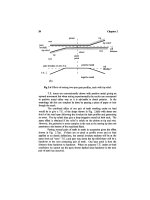
A
spur gear, especially
if an old
design,
will give
a
T.E. with
a
strong regular excitation
at
once
per
tooth
and
harmonics
(Fig
3.1),
even
when
loaded.
The
idea
of
using
a
helical gear
is
that
if we
think
of a
helical
gear
as a
pack
of
narrow spur gears,
we
average
out the
errors associated with
each
"slice"
via the
elasticity
of the
mesh
by
"staggering"
the
slices.
If
we
have
a
helical gear which
is
exactly
one
axial pitch wide,
the
theoretical length
of the
line
of
contact remains constant. Fig.
3.2(a)
shows
a
true view
of the
pressure plane which
is the 3-D
"unwrapping
band"
that
unreels
from one
base cylinder
and
reels onto
the
other base cylinder.
With
a
spur gear
the
contact
"point"
in end
view, i.e., 2-D, appears
as a
straight line parallel
to the
axis,
but
with
a
helical gear
in
3-D,
the
contact line
is
angled
at the
base helix angle
afc.
As
each section along
the
face
width will
be at a
different
point
in its
once-per-tooth
meshing cycle,
there will
be an
elastic averaging
of
errors giving reduced T.E. Fig.
3.2(b)
shows
that
if the
slices
are
staggered,
the
total amount
of
interference
and
force
remains roughly constant.
In
practice,
using
a
helical gear
is
found
to
improve matters
but not as
much
as
might
be
hoped.
The
idea
is
right
but the
realities complicate
life
since
we can
rarely
get the
axial alignment
of two
helical gears accurate enough. There
are
four
tolerances involved even before
we
start thinking about elastic
effects
on
gear
bodies, supporting
shafts,
bearings
and
casing.
' 1
tooth
'
rotation
Fig 3.1
Typical section
of
T.E.
of
meshing spur gears.
27
28
Chapter
3
pitch
_
line
axial
facewidth
Fig
3.2 (a)
View
of
pressure plane
of
helical gear showing contact lines.
elastic
interference
on
each slice
combined
profile
shape
one
contact
line
position
of
slices
axial facewidth
Fig 3.2 (b)
Total
of
interferences
on
slices along contact lines summing
to a
roughly
steady value.
A
theoretical mean mesh deflection
of
about
15
u,m
(200
N/mm
loading)
may
easily
be
associated with
a 30
um
(1.2
mil) misalignment over
a
150
mm (6
inch)
face
width. Hence
an
angular error
of 2 in
10,000 still gives
100%
overload
at one end and
zero loading
at the
other. With this variation
in
load
the
elastic averaging
effects
along
the
helix
are
much less
effective
and
the
helical gear transmission errors start
to
rise toward
those
of a
spur
gear.
Theoretical Helical
Effects
29
Increasing helix angle
so
that there
are
several axial pitches
in a
face
width
improves
the
elastic averaging
effect
under load
but
penalties exist
in
increased axial loads
and
lower transverse contact ratios.
3.2
Loading along contact
line
Another
major
effect
with
helical
gears
is
indicated
in
Fig.
3.3
which
is
a
view
of a
single tooth
flank
showing
a
contact line across
the
face.
As the
mesh
progresses,
the
contact line comes onto
the
tooth
face
at the
lower right
corner,
extends
and
travels across
the
face,
and
then disappears
off
the top
left
comer.
With this engagement pattern there
is no
longer
the
necessity
to
achieve
a
smooth run-in with
tip
relief because
we can do it
with
end
relief.
In
a
high power gear such
as a
turbine reduction gear
a
typical tooth
face
is
much
wider (axially) than
it is
high. This
can
give
us a
large strength bonus
as the
full
loading
per
unit length
of
line
of
contact
can be
maintained nearly
up
to the
tips
of the
teeth.
tip and
root
relief
limits
/N.
tooth
tip
7
contact
line
__
— —
i
i
tooth
root
start
start
ofend
ofend
relief
relief
Fig 3.3
Theoretical
flank
contact line
on a
helical tooth face.
There
is
less tooth
face
"wasted"
as a
result
of
tapering
in
over
two-
thirds
of a
module
at
each
end of the
tooth, compared with more than
a
module
(in
roll distance)
at top and
bottom
if the
gear
is
designed
as a
spur
gear.
A
chamfer
is
needed
at the
tooth tips
as it is
also needed
at the end
faces
of a
spur gear
to
prevent corner loading which gives very high local
stresses
and
gives
oil film
failure.
This
stress
relief
chamfer
is
small
in
extent
compared with (long)
tip
relief which
can
come
one
third
of the way
down
the
working flank.