Handbook of Lubrication P2 doc
Bạn đang xem bản rút gọn của tài liệu. Xem và tải ngay bản đầy đủ của tài liệu tại đây (1.04 MB, 20 trang )
sensitive to an element such as oxygen to surface coverages of as little as one hundredth of
a monolayer and analyzes to a depth of four or five atomic layers.
AES analysis uses a beam of electrons just as with LEED, but the electron energy is
higher, usually 1500 to 3000 eV. Incident electrons strike the sample surface, penetrate the
electron shells of outermost surface atoms, and cause ejection of a second electron called
an Auger electron. The ejected electron carries with it an energy characteristic of the atom
from which it came. Measuring the energy of the ejected electron identifies its elemental
source. The electron energies detected can be recorded on a strip chart or an oscilloscope
(see References for details).
An ordinary iron surface with normal surface contaminants will yield an Auger spectrum
such as Figure 6a which contains peaks for sulfur, carbon, oxygen, and iron. The carbon
and sulfur have two possible origins: impurities in the bulk iron which have segregated to
the surface or adsorbates such as carbon monoxide, or carbon dioxide from the environment.
The oxygen peak results from iron oxides present on the surface or adsorbates such as carbon
compounds or water vapor. The three iron peaks originate from iron oxides and the iron
metal.
If the surface of Figure 6a is bombarded with argon ions, contaminants can be knocked
off leaving only iron with the spectrum in Figure 6b. The added low energy iron peak at
the left end of the spectrum is easily lost when the surface is contaminated.
The shapes of Auger peaks can provide considerable information on the source of an
element such as carbon, as demonstrated in Figure 7. The upper carbon Auger peak arises
Volume II21
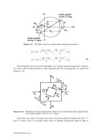
FIGURE 4.Atomic packing on var-
ious crystallographic planes and in
various directions. For face-centered
cubic materials. (a) Appearance of
several crystal planes; (b) the (111)
plane.
Copyright © 1983 CRC Press LLC
from carbon which segregated on the surface of the molybdenum. The second peak is from
adsorbed carbon monoxide, while the third peak is from graphite.
X-Ray Photoemission Spectroscopy (XPS)
XPS is a surface tool which can determine the molecular structure from which an element
came. XPS was formerly called electron spectroscopy for chemical analysis (ESCA).
22 CRC Handbook of Lubrication
FIGURE 5. Three LEED patterns from an iron (110) surface, (a) Carbon contaminant; (b) argon bombarded; and
(c) clean surface (110V).
FIGURE 6. Auger spectra for an iron surface (a) before and (b) after sputter
cleaning.
a
b
c
b
a
Copyright © 1983 CRC Press LLC
With XPS a monochromatic X-ray beam is used as the energy source. The beam causes
ejection of electrons with kinetic energies characteristic of the surface atoms. Aspectrum
of the elements present is obtained by plotting the total number of electrons ejected as a
function of kinetic energy. XPS gives binding energies of the elements which enables
identification of the compounds in which these elements exist. The binding energy of the
electrons ejected from the surface is determined by their chemical environment and is roughly
a function of the atomic charge.
The binding energy measured with XPS will be altered by changing the particular elements
bound to the element being examined. Elemental sulfur has a characteristic binding energy
of 162.5 eV. Negatively charged S
−2
has a lower binding energy. When oxygen is bound
to the sulfur, the sulfur binding energy increases. Further, the SO
4
−2
structure has a greater
binding energy than SO
3
−2
which can be used to distinguish between sulfur bound in these
two states.
Other Techniques
Over 70 surface tools have been developed for analysis and chemical characterization. A
few more commonly used techniques are indicated by their acronyms in Table 1. The
nondestructive techniques are nuclear back scattering spectroscopy (NBS) and electron mi-
croprobe (EM). Auger electron spectroscopy (AES), X-ray photoemission spectroscopy (XPS
or ESCA), ion-scattering spectroscopy (ISS), and appearance potential spectroscopy (APS)
are destructive only if sputter etching or depth profiling is used.
Two techniques which are destructive are secondary ion mass spectroscopy (SIMS) and
glow discharge mass spectroscopy (GDMS). These techniques detect the species sputtered
from the surface (see book by Kane and Larrabee in the References for more details). Note
from Table 1 that they both detect all elements except hydrogen and helium, provide excellent
chemical identification, and have sensitivities of surface elements to as little as 0.01 mono-
layer. Their disadvantage is that they must be operated in a vacuum system.
Probably the most versatile tool is the scanning electron microscope (SEM). It is extremely
useful in obtaining a view of features on a surface such as asperities, surface irregularities,
and topography where adhesion and wear have occurred. When SEM has incorporated into
it X-ray energy dispersive analysis, both topography and chemistry can be determined. The
X-ray analysis is not a surface analytical tool, but it can provide considerable information
where material transfer takes place in adhesion or sliding. An SEM photomicrograph of an
Volume II 23
FIGURE 7. Auger electron spectra of car-
bon. (a) Segregated at a Mo(110) surface
during initial cleaning (labeled Mo-C); (b)
CO on a clean Mo(110) surface (labeled Mo-
CO); and (c) in graphite.
Copyright © 1983 CRC Press LLC
24 CRC Handbook of Lubrication
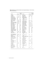
TABLE 1
COMPARATIVE TABLE FOR THE VARIOUS TECHNIQUES USED FOR THE CHEMICAL
CHARACTERIZATION OF SURFACES
NBS EM AES XPS ISS SIMS GDMS APS
Destructive to sample No No No No No Yes Yes No
(in general)
Elements that can be Heavy Z ≥ 4 Z ≥ 3 Z ≥ 3 Z ≥ 3 All All except Z ≥ 3
detected He, Ne
Elemental F G E E E G G E
identification
a
Sensitivity (typical, in 50 5 −0.01 <0.01 −0.01 <1 ~1 ≤0.1
monolayers)
Detectability (i.e., NA 100 <1 NA NA 1 100 NA
ppm)
b
Results are (in Abs Abs Abs Abs Abs Abs Abs Abs
principle)
c
Depth probed (in Å) 10
4
10
4
—10
5
15—20 15—75 3 ~5 × 10—10
4
~10
10
4
Depth distribution of Yes Yes Y/d No Yes Yes Yes Y/d
elements
d
Chemical (i.e., binding) No Yes Yes Yes No No No Yes
information
a
E, Excellent; G, good; F, fair.
b
NA, Not applicable.
c
Rel, Relative; Abs, absolute.
d
Y/d, Yes, if destructive.
From Kane, P. F. and Larrabee, G. B., Eds., Characterization of Solid Surfaces, Plenum Press, New York, 1974. With permission.
Copyright © 1983 CRC Press LLC
aluminum surface is shown in Figure 8a after sliding on an iron surface. The photomicrograph
reveals surface topography while the X-ray map for iron reveals the white patch in Figure
8b where iron is detected on the aluminum wear surface.
PROPERTIES OF SURFACES
Metallurgy and Crystalline Structure
The crystal structure of ideal surfaces has already been examined in Figure 4. All engi-
neering surfaces vary from this ideal and have grain boundaries which develop during
solidification as large defects which exist in the solid and extend to the surface. They do
not possess a regular structure, are highly active regions, and on the surface are very energetic.
Lesser defects include subboundaries, twins, dislocations, interstitials, and vacancies.
Subboundaries are low-angle grain boundaries and usually occur where there is only a
slight mismatch in orientation of adjacent grains on either side of the boundary. When the
crystal lattices of adjacent grains are slightly tilted one toward the other, there is a tilt
boundary. Where the lattices remain parallel but one is rotated about a simple crystallographic
axis relative to the other with the boundary being normal to this axis, a twist boundary
develops. The twin boundary occurs where there is only a degree or two of mismatch with
the twins being mirror images. They are frequently seen on basal planes of hexagonal metals
with deformation.
Dislocations are atomic line defects in crystalline solids. They may be subsurface and
terminate at the surface or they may be in the surface. Edge dislocations are entirely along
a line where an extra half plane of atoms exists. Screw dislocations form along a spiral
dislocation line. Small angle boundaries or subboundaries are generally composed of edge
dislocations. These defects in crystalline solids cause them to deviate markedly from the
theoretically achievable strengths of ideal crystals.
Some of the crystalline surface defects are presented schematically in Figure 9. The vacant
lattice site was seen on a real surface in the photomicrograph of Figure 2b. An interstital
atom is crowded into the crystal lattice of Figure 9a. Edge and screw dislocations and a
small angle boundary are also shown. Worn surfaces generally have undergone a high degree
of strain and may contain large amounts of lattice distortion and defects such as dislocations.
While initial dislocations cause a reduction in strength, their multiplication and interaction
during deformation increase surfacial strength. Microhardness is generally higher in grain
boundaries than in grains.
With plastic deformation, the strain generally produces a reduction in recrystallization
Volume II25
FIGURE 8. (a) Electron image of aluminum rider wear scar; (b) iron Kαmap of aluminum rider.
a
b
Copyright © 1983 CRC Press LLC
temperatures of material at the surface. The combination of strain and temperature can then
bring about surface recrystallization which has an annealing effect. This process relieves
lattice strain and stored energy, with a sharp reduction in the concentration of surface defects.
In a dynamic, nonequilibrium system such as encountered in sliding, rolling, or rubbing,
surface layers may be strained many times, recrystallized, and then strained again.
Solid State Bonding
What holds atoms or molecules in various arrangements and imparts to solids their basic
cohesive strength? The answer lies in the bonding. Bonding in crystalline solids can be of
four types, as shown in Figure 10: van der Waals, ionic, metallic, and covalent.
Van der Waals forces, the weakest holding solids together, are attributed to nothing more
than fluctuations in the charge distributions within atoms or molecules. These forces can be
represented in bonding the atoms of an inert gas together when solidified. Very littleenergy
is required to accomplish sublimation.
An ionic bond is very strong, and some high-strength solids are held together by it. This
bond is represented in Figure 10 by sodium chloride. Electrons are transferred from the
metal to the nonmetal and the resulting ions are held together by the electrostatic forces;
developed. Aluminum and magnesium oxides are two tribological solids with this bonding.
With metals, the valence electrons are taken away from individual atoms to form a sea
of electrons. This results in positively charged ions immersed in electrons. This bonding
gives metals their good thermal and electrical conduction characteristics.
The fourth type of bonding is covalent where electrons are simply shared. This is indicated
in Figure 10 by the overlapping of carbon atoms in diamond (the hardest material and most
resistant to deformation). At the same time, the covalent bond is found in organic molecules
in polymers and lubricants where it is relatively weak. No other bonding type possesses
such a wide range of strengths.
26CRC Handbook of Lubrication
FIGURE 9. Crystalline defects in solids.
Copyright © 1983 CRC Press LLC
CHEMISTRYOF SURFACES
Clean Surfaces
Very clean surfaces are extremely active chemically. Acopper atom which lies in a (111)
plane in the bulk of the solid will have a coordination number of 12: it is bonded to 12
nearest neighbors. That same copper atom at the surface will, however, have a coordination
number of only 9 with only 9 nearest neighbors. The energy normally associated with bonding
to three additional atoms is now available at the surface. This energy expressed over an area
of many atoms is referred to as the surface energy.
Surface energy is also the energy necessary to generate a new solid surface by the separation
of adjacent planes. The energy required for separation is a function of the atomic packing.
For example, for copper the atomic packing density is greatest in (111) planes (greatest
number of nearest neighbors within the plane). As a result, bonding forces between adjacent
(111) planes is least and the surface energy of new (111) surfaces generated, say by cleavage,
is less than for the (110) and (100) planes. This lesser binding strength is also a function
of the distance between adjacent planes, it being greater between adjacent (111) planes than
between (110) and (100) planes.
Because surface atoms have this unused energy, they can interact with each other, with
other atoms from the bulk, and with species from the environment. Not bound as rigidly as
atoms in the bulk, surface atoms can alter their lattice spacing by reconstruction, as depicted
schematically in Figure 11. By use of LEED, this process has been found to occur in some
crystalline solids but not in others.
In solids containing more than a single element, atoms from the bulk can diffuse to the
surface and segregate there. In a simple binary alloy, solute atom can diffuse from near
surface regions to completely cover the surface of the solvent. This has been observed for
many binary systems including aluminum in copper, tin in copper, indium in copper, alu-
minum in iron, and silicon in iron. One hypothesis for the segregation mechanism is that
the solute segregates on the surface because it reduces the surface energy. Asecond theory
is that the solute produces a strain in the crystal lattice of the solvent, and this unnatural
lattice state ejects solute atoms from the bulk.
Chemisorption
In addition to the solid interacting with itself at the surface, the surface can interact with
Volume II27
FIGURE 10.The principle types of crystalline
binding forces.
Copyright © 1983 CRC Press LLC
the environment. This interaction alters the surface chemistry, physics, metallurgy, and
mechanical behavior. If a metal surface is very carefully cleaned in a vacuum system and
then a gas such as oxygen admitted, the gas will adsorb on the metal surface. Except with
inert gases, this adsorption results in chemical bonding in a chemisorption process indicated
schematically in Figure 11. Once adsorbed, these films are generally difficult to remove.
Where the species adsorbing on a clean surface is an element, adsorption is direct. Surface
atoms of the solid retain their individual identity as do atoms of the adsorbate, yet each is
chemically bonded to the other. When the adsorbing species is molecular, chemisorption
may be a two-step process, first dissociation of the molecule upon contact with the energetic
clean surface followed by adsorption of the dissociated constituents.
Chemisorption is a monolayer process. Bond strengths are a function of chemical activity
of the solid surface (surface energy), degree of surface coverage of that adsorbate or another
adsorbate, reactivity of the adsorbing species, and its structure. The higher the surface energy
of the solid surface, the stronger the tendency to chemisorb. In general, the high-energy,
low-atomic density crystallographic planes will chemisorb much more rapidly than will the
high-atomic density, low-surface energy planes. Hydrogen sulfide will adsorb more readily
on (110) and (100) surfaces of copper than on (111) surfaces.
The metal surface has an effect. Copper, silver, and gold are noble metals and many of
their properties are similar. Yet, oxygen will chemisorb relatively strongly to copper, weakly
to silver, and not at all to gold. Reactivity of the adsorbent is also important. Of the halogen
family fluorine will adsorb more strongly than chlorine, chlorine than bromine, and bromine
than iodine.
The structure of the adsorbing species is also significant as can be demonstrated with
simple hydrocarbons. If ethane, ethylene, and acetylene are adsorbed on an iron surface,
tenacity of the chemisorbed films is in direct relation to the degree of bond unsaturation.
Acetylene is much more strongly bound to the surface than ethylene, which in turn is more
strongly bound than ethane. The carbon to carbon bonds break on adsorption and bond to
the iron. The greater the number of carbon to carbon bonds, the greater the resulting number
of carbon to iron bonds.
Compound Formation
Compound formation on tribological surfaces is extremely important. The naturally oc-
curring oxides present on metals prevents their destruction when sliding on other solids.
Extreme pressure additives and many antiwear materials placed in oils perform by compound
formation with the surface to be lubricated.
Once present on a surface, chemisorbed films often interact with that surface to form
chemical compounds. The surface material and the adsorbate form an entirely new substance
with its own characteristic properties. The process continues by diffusion of both the solid
surface material and the environmental species into the film. The compound can grow in
thickness on the surface if the film is porous and allows for two-way diffusion as shown in
28 CRC Handbook of Lubrication
FIGURE 11. Possible surface events.
Copyright © 1983 CRC Press LLC
Figure 11. An example is the oxidation of ironin moist air which continues to consume
iron. In contrast, oxidation of aluminum to form aluminum oxide results in a thin, dense
oxide of 120 Å which retards diffusion and film growth.
Environmental Effects
Chemical, physical, and metallurgical properties of atomically clean metal surfaces are
markedly altered by foreign substances. This is extremely important because most real
surfaces are not atomically clean but have film(s) present on their surface (Figure 1). The
wide variations found in the literature for surface properties of materials can be attributed
to the effect of these films.
Presence of oxides on metal surfaces has been observed to produce a surface hardening
effect. One explanation for this hardening is that the oxygen pins dislocations which emerge
at the surface, impeding their mobility.
Other surface films increase ductility. For example, water on alkali halide crystals will
allow an otherwise brittle solid to deform plastically. This effect is also observed with
ceramics. Magnesium oxide (MgO) is normally very brittle with a surface hardness in the
clean state of about 750 kg/mm
2
. Figure 12 presents the hardness of MgO as a function of
indentation time in dry toluene and moist air. The increased surface ductility in the presence
of water is striking, and the difference increases with increasing indentation time. This
change with time makes the film effect a true surface property and not simply a lubricating
effect produced by the water.
In the 1920s Rehbinder found that certain organic molecules on the surface of solids
produced a softening. Such substances as oleic acid in vaseline oil were examined. This
surface softening by lubricating substances can be very beneficial in certain instances such
as in arresting the formation of fatigue cracks in bearing surfaces.
REFERENCES
Introduction
1. ASTM,Symposium on the properties of surfaces, ASTM Mater. Sci. Ser. 4, 1963.
2. SCI, Surface Phenomena of Metals, Monograph No. 28, Society of Chemical Industry, London, 1968.
3. Anon., Conference on clean surfaces, Ann. N.Y. Acad. Sci., 101, 583, 1963.
4. Adamson, A. W., Physical Chemistry of Surfaces, 2nd ed., Interscience, New York, 1967.
5. Gatos, H. C., Ed.,The Surface Chemistry of Metals and Semiconductors, John Wiley &Sons, New York,
1960.
6. Blakely, J. M., Ed., Surface Physics of Materials. Vols. 1 and 2, Academic Press, New York, 1975.
Volume II29
FIGURE 12. Illustration of the effect
of time on microhardness of MgO in tol-
uene and in moist air (after Westbrook).
21
Copyright © 1983 CRC Press LLC
Method of Characterization of Surfaces
7. Kane, P. F. and Larrabee, G. B., Eds., Characterization of Solid Surfaces, Plenum Press, New York,
1974.
8. Bunshah, R. F., Ed., Technique of Metals Research, Vol. 2, Techniques for the Direct Observation of
Structure and Imperfections, Part 2. Interscience, New York, 1969.
9. Blakely, J. M., Ed., Surface Physics of Materials, Materials Science Series, Vols. 1 and 2, Academic
Press, 1975.
10. Somoraji, G. A., Principles of Surface Chemistry, Prentice-Hall, Englewood Cliffs, N.J., 1972.
11. Proc. 2nd Int. Conf. on Solid Surfaces. II, Jpn. J. Appl. Phys., Suppl. 2, 1974.
12. Muller, E. W. and Tsong, T. T., Field Ion Microscopy, American Elsevier, New York, 1969.
Properties of Surfaces
13. Ehrlich, G., Atomistics of metal surfaces, Surface Phenomena of Metals, Monograph No. 28, Society of
Chemical Industry, London, 1968, 13.
14. Hayward, D. O. and Trapnell, B. M. W., Chemisorption, 2nd ed., Butterworths, Washington, D.C.,
1964.
15. Ferrante, J. and Buckley, D. H., A review of surface segregation, adhesion and friction studies performed
on copper-aluminum, copper-tin, and iron-aluminum alloys, ASLE Trans., 15(l), 18, January 1972.
16. Burke, J. J., Reed, N. L., and Weiss, V., Eds., Surfaces and Interfaces 11, Physical and Mechanical
Properties. Syracuse University Press, New York, 1968.
17. Westwood, A. R. C. and Stolaff, N. S., Eds., Environment-Sensitive Mechanical Behavior, Metallurgical
Society Conference, Vol. 35, Gordan and Bovach Science Publishers, New York, 1966.
18. Jenkins, A. D., Ed., Polymer Science, A Materials Science Handbook, Vols. 1 and 2, North-Holland,
Amsterdam. 1972.
19. Buckley, D. H., Definition and Effect of Chemical Properties of Surfaces in Friction, Wear, and Lubrication,
NASA TM-73806, National Aeronautics and Space Administration, Washington, D.C., 1978.
20. Likhtman, V. I., Rehbinder, P. A., and Karpenko, G. V., Effect of Surface-Active Media on the
Deformation of Metals, Chemical Publishing Company, New York, 1960.
21. Westbrook, J. H., Ed., Mechanical Properties of Intermetallic Compounds, John Wiley & Sons, New
York, 1960.
30 CRC Handbook of Lubrication
Copyright © 1983 CRC Press LLC
FRICTION
K. C. Ludema
DEFINITION OF FRICTION
The usual engineering definition of friction is resistance to relative motion of contacting
bodies. Commonly encountered types of friction include dry, lubricated, sliding, rolling,
dynamic or kinetic, static or starting or limiting, internal or hysteretic, external and viscous.
Magnitude of friction is usually expressed as a coefficient of friction µ, which is the ratio
of the force F required to initiate or sustain relative tangential motion to the normal force
(or weight) N which presses the two surfaces together. Thus, µ = F/N. In the early years
of technology, the value of F/N was found to be reasonably constant for each class of
materials. In modern technology, µ is regarded to be widely variable, depending on oper-
ational variables, lubricants, properties of the substrate, and surface films.
1-5
CLASSIFICATION OF FRICTIONAL CONTACTS
Friction is a phenomenon associated with mechanical components. Some are expected to
slide and others are not. Four categories within which high or low friction may be desirable
are given below.
1. Force transmitting components that are expected to operate without displacement.
Examples fall in the following two classes:
a. Drive surfaces or traction surfaces such as power belts, shoes on the floor, hose
clamps, and tires and wheels on roads or rails. Some provision is made for sliding,
but excessive sliding compromises the function of the surfaces. Normal operation
involves little or no macroscopic slip. Static friction is often higher than the dynamic
friction.
b. Clamped surfaces such as press-fitted pulleys on shafts, wedge-clamped pulleys
on shafts, bolted joining surfaces in machines, automobiles, household appliances,
etc. To prevent movement, high normal forces must be used and the system is
designed to impose a high but safe, normal (clamping) force. In some instances,
pins, keys, surface steps, and other means are used to guarantee minimal motion.
In the above examples, the application of a (friction) force frequently produces
microscopic slip. Since contacting asperities are of varying heights on the original
surfaces, contact pressures within clamped regions may vary. Thus, the local re-
sistance to sliding varies and some asperities will slip when low values of friction
force are applied. Slip may be referred to as microsliding as distinguished from
macrosliding, where all asperities are sliding at once. The result of oscillatory
sliding of asperities is a wearing mechanism, some cases of which are known as
fretting.
2. Energy absorption-controlling components such as in braking and clutching. Efficient
design usually requires rejecting materials with low coefficient of friction because
such materials require large values of normal force. Large coefficients of friction would
be desirable except that suitably durable materials with high friction have not been
found. Thus, many braking and clutching materials have intermediate values of coef-
ficient of friction in the range between 0.3 and 0.6. An important requirement of
braking materials is constant friction, in order to prevent brake “pulling” and unex-
pected wheel lockup in vehicles. A secondary goal is to minimize the difference
Volume II 31
Copyright © 1983 CRC Press LLC
between the static and dynamic coefficient of friction for avoiding squeal or vibrations
from brakes and clutches.
3. Quality control components that require constant friction. Two examples may be cited,
but there are many more:
a. In knitting and weaving of textile products, the tightness of weave must be controlled
and reproducible to produce uniform fabric.
b. Sheet metal rolling mills require a well-controlled coefficient of friction in order
to maintain uniformity of thickness, width, and surface finish of the sheet and, in
some instances, minimize cracking of the edges of the sheet.
4. Low friction components that are expected to operate at maximum efficiency while a
normal force is transmitted. Examples are gears in watches and other machines where
limited driving power may be available or minimum power consumption is desired,
bearings in motors, engines and gyroscopes where minimum losses are desired, and
precision guides in machinery in which high friction may produce distortion.
SURFACE CHARACTERISTICS AND STATIC CONTACT AREA
Frequently the coefficient of friction is more dependent upon surface properties and surface
finish than on substrate properties. Substrate properties, however, influence both the surface
finish achieved in processing and the kinetics of adsorption of chemical species.
Surface Structure and Finish
With the exception of surfaces that solidify from the liquid (either in air, in vacuum, or
in contact with a mold), most technological surfaces are formed by a cutting operation.
Coarse cutting is done with a cutting tool in a lathe, drill press, milling machine, etc. Finer
cutting is done with abrasives by grinding, honing, lapping, etc.
Cutting is simply localized fracture. Each individual microfracture joins another and/or
extends into the substrate. The orientation of surface facets and the direction taken by
subsurface cracks are often dependent upon the structure of the material. Seriousness of a
substrate crack will probably depend upon the toughness of the material. For example, in
cast irons and notably in white cast iron, machining often forms cracks that extend into the
substrate and in fact may loosen some grains from the matrix. In more ductile materials,
the cracks that extend into the substrate are less likely to be harmful and yet they may
constitute a stress concentration from which fatigue cracks may emanate. Cracks may also
become corrosion cells.
Many surfaces are formed by ductile fracture mechanisms with a high amount of plastic
strain and residual stress remaining in the surface. All of these conditions may influence
the coefficient of friction either from the beginning of sliding or as a result of surface
alteration during sliding.
Adsorption on Surfaces
Material cutting operations expose atoms or molecules, formerly in the substrate, to the
environment around the material. Oxygen in the air is very reactive with most metals and
is usually the first to adsorb and form oxides on metal surfaces. After oxides of between
20 Å to 100 Å thick form, the rate of oxidation diminishes and other gases adsorb. In air,
for example, a significant amount of water vapor adsorbs on oxides and on other materials
such as gold and plastic which do not oxidize quickly. The adsorbed gases can be the same
thickness as the oxide film.
Adsorption occurs very quickly. Pure oxygen gas at atmospheric pressure produces a 50%
coverage by adsorption in about 1.75 × 10
−9
sec.
The influence of all surface films on friction is not always the same. It might be expected
32 CRC Handbook of Lubrication
Copyright © 1983 CRC Press LLC
that adsorbed water would act as a liquid lubricant, and that some oxides or hydroxides
might act as solid lubricants. On the other hand, some oxides such as aluminum oxide
(A1
2
O
3
) are abrasive and under some conditions greatly increase friction.
Estimating Contact Area
Explanations of friction are based upon the detailed nature of contact between two bodies.
Historically the measurement of real contact area was attempted in order to decide between
the two major theories of friction outlined below. The methods used include electrical
resistance, heat transfer, total internal reflectance of an optical element pressed against a
metal surface, phase contrast microscopy, ultrasonic transmission, election emission phe-
nomena, computer simulation, large-scale surface model studies, and analytical methods
based on the mechanics of solids. Most methods are unsatisfactory in that either the obser-
vations are not made in real time, or the method is incapable of distinguishing between
many small points of contact vs. few large regions. Results from all methods, however,
produce the same conclusion: the contact area increases with normal load and when a friction
force is applied.
An adequate description of the behavior of asperities may be gained by a simple analytical
model. Representation as a sphere is reasonable since most asperities are reasonably rounded
rather than sharp or jagged. For the simplified case of a sphere pressed against a flat surface,
the radius of contact, a, may be calculated as follows:
6
where N is the normal load, r is the radius of the sphere, v is Poisson’s ratio, E is Young’s
modulus, and subscripts 1 and 2 refer to the two materials if the sphere and flat plate are
of different materials. The pressure distribution over the area of contact is semielliptical.
The average pressure is P
m
= N/πa
2
and the maximum pressure q
o
at the center of contact
is 3/2 P
m
. Thus, q
o
= (3/2) N/πa
2
.
Other equations are available that give the stress state of all points in the substrate
6
and
may be used to calculate the limits of elastic behavior. A principle of plasticity is that plastic
flow will occur whenever the difference between the largest and smallest stresses in per-
pendicular directions at a point is equal to the yield strength of the material. As normal load
increases, the conditions for plastic flow first occur directly under the center of the ball at
a depth of 0.5a and plastic yielding will occur when P
m
= 1.1 Y, where Y equals the tensile
yield strength of the material.
Experimental work has shown that continued loading of the ball produces a progressively
larger plastically deformed region.
1
The mean contact pressure increases and finally ap-
proaches 2.8 Y. Other experimental work on practical surfaces indicates that very many
asperities are in the advanced state of plastic flow.
7
From this we may estimate the real area
of contact, A, between nominally flat surfaces touching each other at asperities is approx-
imately equal to N/3Y. For a metal with a yield strength Y = 15,000 psi, a 1-in. (2.5-cm)
cube pressed with a load N as shown in the table below produces a real contact area A
r
,
Volume II 33
The above paragraph implies that contact area increases linearly with applied load. Re-
Copyright © 1983 CRC Press LLC
Table 1
COEFFICIENT OF
ADHESION FOR
VARIOUS METALS
search suggests that real contact area between nominally flat surfaces increases more neary
as the 0.8 power of applied load.
7
Adhesion and Peeling
In the above model of the elastic sphere pressing against an elastic flat plate, the radius
and area of contact increase as the normal load increases. As a matter of practical experience,
the area of contact also returns to 0 (point contact) as the load is decreased. From such
observations it is easy to assert that there is no adhesion between surfaces. This at least has
been the argument against adhesion being operative in friction. On the other hand, measurable
adhesion does occur during contact between two surfaces that were vigorously cleaned in a
high vacuum, which makes a total denial of adhesion untenable.
The influence of a cycle of loading and unloading of a sphere on a flat plate with and
without adhesion may be seen in the illustration of a rubber ball pressed against a rigid flat
surface. As each increment of load is added, a ring of larger diameter of contact forms
between the ball and flat plate. The reverse occurs upon progressive removal of the load.
If the flat surface were covered with a tacky substance, the increment of added load would
produce increasing contact area as before, but upon decrease in load the outer ring of contact
will not readily separate. A state of tension will exist across the adhesive bond. As the next
increment of load reduction occurs, the second ring inward experiences higher tensile stress,
etc. Finally, the normal load N may be completely removed but the ball still remains in
contact with the flat surface. The stress state over the contact region is one of tension at the
outer edges of contact and compression in the middle of contact to achieve static equilibrium.
The compression force constitutes a recovery force and its origin is in the elastic strain field
“stored” in the rubber ball.
At the outer edges of contact where the stresses are highest, there is also a sharp crack
or stress concentration. Thus, the conditions are right for “peeling” or continuous fracture
of adhesive bonds at the outer edge of contact. With visco-elastic materials the fracture
would be time-dependent but with metals the fracture would occur progressively as the load
decreases. The bonds of a ductile material do not fracture as readily as those of a brittle
material, thus leaving a residual contact region. A force, – N, required to separate a sphere
from a flat plate once N is removed, divided by N may be called the coefficient of adhesion
A, with A = | – N/N|. Absolute values for various metals are shown in Table 1.
34 CRC Handbook of Lubrication
Copyright © 1983 CRC Press LLC
MECHANISMS OF SLIDING FRICTION
Recent Understanding
Research in the last 50 years has focused on whether friction is due to adhesion or the
interlocking of asperities. The interlocking theory views surfaces as being composed of
relatively rigid asperities which must follow complex paths to move around or over each
other. The adhesion theory assumes that two contacting surfaces will bond or weld together
and the resulting bonds must be broken for sliding to occur.
There are now two convincing arguments against the interlocking theory. First is the
observation that monomolecular films of lubricants decrease the friction of the sliding pair
by a factor of five or more while having a negligible effect on the size and shape of asperities.
The second argument stems from the statement in the ‘interlocking theory’ that the coefficient
of friction is related to the steepness of asperities, implying that the force to slide a body
up an inclined plane has the horizontal component F. Since with continued motion the force,
F, must be constantly applied, one would suppose that the upper body continues to rise and
would soon be separated some distance from the lower body!
The adhesion theory has been criticized for two reasons. One is based on the belief that
adhesion is a force measured normal to surfaces whereas friction is a force measured parallel
to the surfaces. The second criticism arises from the common experience that surfaces are
readily separated after sliding ceases, requiring no force to separate as would be required
with adhesive bonding.
The modern view is that friction is primarily due to adhesion but an adhesion that is
limited by the oxides and adsorbed gases found on all surfaces during sliding and destroyed
by peeling when load is removed. In some instances of very rough surfaces where some of
the roughness may be due to carbide particles, there may be a second component of friction
due to asperity collision.
Laws of Friction
The earliest law of friction is due to Leonardo DeVinci (1452 to 1519).
8
He observed
that F is proportional to N, where F is the force to initiate sliding and N is the normal force
holding the surfaces together. Amontons (1663 to 1705), a French architect-engineer, in
1699 reported to the French Academy that he found F is roughly equal to N/3 and F is
independent of the size of the sliding body. The specimens tested were copper, iron, lead,
and wood in various combinations, and in each experiment the surfaces were coated with
pork fat (suet). Amontons saw the cause of friction as the collision of surface irregularities.
Coulomb (1736 to 1806), a French physicist-engineer, supported Amontons in stating that
friction is due to the interlocking of asperities. He discounted adhesion (cohesion) as a source
of friction because friction was usually found to be independent of (apparent) area of contact.
While Coulomb was in error in his explanation of friction and he did not improve on the
findings of Amontons, yet today “dry friction” is almost universally known as “Coulomb
friction”. This is taken to mean simple friction, invariant with load, speed, temperature,
starting rate, etc.
The investigators most commonly associated with the adhesion theory of friction are
Bowden and Tabor.
1
An early model from this school began with the idea that the force of
friction is the product of A
r
, the summation of the microscopic areas of contact, and the
shear strength, S
s
, of the bond in that region; i.e., F = A
r
S
s
. To complete the model, the
load, N, was thought to be borne by the tips of asperities, altogether comprising a total area
of contact, A
r
, multiplied by the average pressure of contact, N = A
r
P
f
, where P
f
is the
average pressure of contact on the asperities. Altogether, the coefficient of friction is taken
as
Volume II 35
Copyright © 1983 CRC Press LLC
S
s
is usually approximately Y/2 where Y is the yield strength of the material in tension.
P
f
is usually no more than 3Y. Thus, the ratio S
s
/P
f
is about 1/6, which is not far from 0.2,
a value often found in practice for “clean” metals in air. Using the best estimates for A
r
and S
s
, however, the closest estimate of friction is only 1/10 of the measured values.
Estimation of the real area of contact is generally considered the most difficult problem in
this model.
From 1938 when the above model was proposed, there have been many developments in
technology, particularly in the use of vacuum equipment. In vacuum, the coefficient of
friction is often seen to exceed 0.2 by a large margin and sometimes approaches 40. To
explain such values and other anomalies in friction, Tabor developed a new model based
on principles of biaxial stresses in metals and its influence on plastic strain of the metals.
9
Conceptually, the model of the sphere on the flat plate can be applied here. As load on the
sphere increases, its contact area with the flat plate increases and the stresses pass from the
elastic to the plastic regime. In the elastic regime, a superimposed shear stress on the sphere
would produce an elastic shear strain in the sphere and the contact area between the sphere
and flat plate would not be affected. In the plastic range, however, after a normal load is
applied that produces plastic flow, a horizontal force producing a shear stress in the sphere
would produce a new increment of strain in the direction of the resultant of the initial normal
force and the applied shear force. Thus, the shear force causes a further normal strain in
asperities with the effect of increasing the area of contact. If adhesion increases in proportion
to the area of contact, the area of contact will grow in proportion to the average shear stress
that can be sustained or developed at the interface between the sphere and the flat plate.
The final form of the model is expressed as,
where k = S
i
/S
s
, and S
i
is the shear strength of the interface between the sphere and the
flat plate. If k = 1 in this model, µ = ∞. This corresponds to a clean surface achieved in
a high vacuum. In this state, contact area increases indefinitely as a friction force is applied
until the contact and adhesion area is very large. In this case, it may not be possible to
separate the surfaces and this is defined as the state of seizure. Where some interruption of
surface adhesion occurs, however, the value of S
i
is less than S
s
. The calculated values of
µ for several conditions are shown in the table below.
kµ
0.95 →1
0.8 0.45
0.6 0.25
0.1 0.03
The latest model of Tabor is not totally satisfying because of our inability to comprehend
S
i
in realistic terms. It may be either an average shear strength over a contact region, or the
fraction of surface over which very high adhesion occurs leaving other areas to have no
adhesion. Other uncertainties in the model are due to the manner in which the plastic flow
properties of materials were simplified, and it does not explain the effect of surface roughness
in friction. On the other hand, the interlocking theory is not aided by the frequent observation
that µ increases as surface finish decreases below a roughness of 10 µin. Neither of the
Tabor models or the interlocking theory explain the influence of close lateral proximity of
asperities which imposes a limit on the high value of µ. This is the case in metal working
where there is high-contact pressure.
36 CRC Handbook of Lubrication
Copyright © 1983 CRC Press LLC
COEFFICIENT OF FRICTION
Measurement of Friction
Measurement of the coefficient of friction involves two quantities, namely F, the force
required to initiate and/or sustain sliding, and N, the normal force holding two surfaces
together. Some of the earliest measurements of the coefficient of friction were done by an
arrangement of pulleys and weights as shown in Figure 1. Weight P
s
is applied to the pan
until sliding begins and one obtains the static, or starting, coefficient of friction with µ
s
=
P
s
/N. If the kinetic coefficient of friction µ
k
is desired, a weight is applied to the string and
the slider is moved manually and released. If sliding is not sustained, more weight is applied
to the string for a new trial until sustained sliding of uniform velocity is observed. In this
case, the final weight P
k
is used to obtain µ
k
= P
k
/N.
A second convenient system for measuring friction is the inclined plane shown in Figure
2. The measurement of the static coefficient of friction consists simply in increasing the
angle of tilt of the plane to θ when the object begins to slide down the inclined plane. By
simple trigonometric relations,
F/N = W sin
θ
/W cos
θ
= tan
θ
= µ
If the kinetic coefficient of friction is required, the plane is tilted and the slider is advanced
manually. When an angle, θ, is found at which sustained sliding of uniform velocity occurs,
tan θ is the kinetic coefficient of friction.
As technology developed, it became possible to measure the coefficient of friction to a
Volume II 37
FIGURE 1. String-pulley-weight measurement of coefficient of friction.
FIGURE 2. Tilting plane measurement of coefficient of friction.
Copyright © 1983 CRC Press LLC
high accuracy under a wide range of conditions. Force measuring devices for this purpose
range from the simple spring scale to devices that produce an electrical signal in proportion
to an applied force. The principle of the instrumented devices is similar to the spring scale
in measuring the elastic deflection of machine elements due to friction forces and normal
forces on the sliding pair. The deflection can be measured by strain gages, capacitance
sensors, inductance sensors, piezoelectric materials, optical interference, acoustic emission,
moire fringes, light beam deflection, and several other methods. The most widely used
because of its simplicity and reliability is the strain gage system.
Just as there are many sensing systems available, there are also many designs of friction
measuring devices.
10
The unit shown in Figure 3 is attractive because of its simplicity. It
is attached to a prime mover which moves horizontally and may be adjusted vertically to
load the pin against the flat. Strain gages are attached to horizontal flexible sections 1 and
2 to measure the normal force between the pin specimen and the flat plate. Strain gages
attached to vertical flexible section 3 measure friction force by bending of the beam. Designs
incorporating the principle of Figure 3 are usually favored in complex, automatically con-
trolled machinery. The chief disadvantages of this design are (1) the skill required both to
calibrate the instrument and to maintain it, and (2) the inevitable interaction or “cross talk”
between the two force-measuring signals.
Amore complex system which requires less skill to operate is shown in Figure 4. It is
composed of two parts. Part Acan rotate about bearing G in a horizontal plane but is
constrained by a wire between cantilevers x and y. Part B is attached to part Aby bearing
H on a horizontal axis. Aslider test pin is inserted in body B. When the prime mover is
moved vertically downward, the pin presses the flat plate tending to rotate body B in a
clockwise direction which bends cantilever w. With strain gages attached to cantilever w,
the vertical force on the pin may be measured. Motion of the prime mover to the left tends
to rotate the pin about bearing G. Strain gages on cantilever x measure the force of friction
of the pin against the flat plate.
The design shown in Figure 4 avoids the interaction between force signals, which plagues
the design of Figure 3. The two-part design also is nearly insensitive to the amount of
extension of the pin specimen, which is convenient for setup. In addition, wire z in Figure
4 can be removed and the vertical loading on the pin can be conveniently effected by dead
weights. The above designs are a few of many in use. Frequently, it is more convenient to
use two flat surfaces, a shaft in a bearing, or three pins instead of one.
38CRC Handbook of Lubrication
FIGURE 3.One-piece device for measuring pin-on-flat coefficient of friction. Strain
gages on flexible sections 1 and 2 measure normal force; strain gage at 3 measures
friction force by bending of the beam.
Copyright © 1983 CRC Press LLC
Data obtained from friction measuring devices are usually not easy to interpret. For some
sliding pairs a smooth force trace may be obtained on recorder strip chart but frequently the
friction force will drift or wander inexplicably. In other instances, where a flat plate rotates
for example, a repeatable behavior may be found during repeat rotations of the flat plate.
These variations may exceed 10 or 20% of the average force trace (particularly when there
is stick-slip) and have often been explained in terms of the stochastic or statistical nature of
friction. Variations are usually largest when small values of N are used and are reduced at
high values of N, where contact pressures approach the state of fully developed plastic flow.
Analysis of strip chart records is further discussed below.
General Frictional Behaviorand Influence of Variables
Almost all operating parameters (speed, load, etc.) will influence the coefficient of friction.
Some of the variables and their general effects are listed below.
Sliding speed— For metals and other crystalline solids sliding on like materials, the
behavior is as shown in Figure 5.
1
The sliding speeds indicated range from imperceptibly
slow (the tip of the minute hand on a watch moves at about 10
−3
cm/sec) to normal walking
speed (~125 cm/sec) which covers many practical conditions. At very high-sliding speed
(>2500 cm/sec) surface melting may occur to produce a low coefficient of friction. Some
polymers behave as shown in Figure 6
11
for the coefficient of friction of a steel sphere sliding
on PTFE and Nylon 6-6. Note the variation for PTFE, which is usually thought to have a
low and constant coefficient of friction. The coefficient of friction of both polymers increases
with sliding speed over a limited range of speed because sliding invokes a visco-elastic
response in the materials. Few materials slide at higher speeds in practice, producing such
a high coefficient of friction, as tire rubber on most road surfaces. Typical data are shown
in Figure 7
12
for both dry roads and roads wetted by a moderate rainfall.
Temperature— There is usually little effect on the coefficient of friction of metals until
Volume II39
FIGURE 4.Sketch of two-component force-measuring system with attached trans-
ducers and pin sliding on flat plate.
Copyright © 1983 CRC Press LLC
the temperature becomes high enough to increase the oxidation rate (which usually decreases
µ). Increased temperature will lower the sliding speed at which surface melting occurs (see
Figure 5) and increased temperature will shift the curve of coefficient of friction vs. slid-
ingspeed to a higher sliding speed in many plastics (see Figure 6).
Starting rate — Rapid starting from standstill is sometimes reported to produce a low
initial coefficient of friction. In many such instances, the real coefficient of friction may be
obscured by dynamic effects of the systems.
Applied load orcontact pressure — In the few instances that the coefficient of friction
is reported over a large range of applied load, three principles may be seen in Figure 8.
1
The first is that the coefficient of friction normally decreases as the applied load increases.
For clean surfaces, as shown by curve ‘a’, values of µ in excess of 20 are reported at low
load, decreasing to about 0.5 at high loads. An old theory suggests that the ultimate effect
of increasing the contact pressure between clean surfaces is to effect adhesive bonding over
40CRC Handbook of Lubrication
FIGURE 5.General effect of sliding speed on coefficient of friction for metals and other crystalline
solids (e.g., ice).
FIGURE 6.Influence of sliding speed on coefficient of friction of a steel sphere sliding
on PTFE and Nylon 6-6.
Copyright © 1983 CRC Press LLC