Model-Based Design for Embedded Systems- P25 ppsx
Bạn đang xem bản rút gọn của tài liệu. Xem và tải ngay bản đầy đủ của tài liệu tại đây (512.91 KB, 10 trang )
Nicolescu/Model-Based Design for Embedded Systems 67842_C007 Finals Page 206 2009-10-2
206 Model-Based Design for Embedded Systems
13. D. Wiklund and D. Liu, Design, mapping, and simulations of a 3G WCD-
MA/FDD base station using network on chip, in Proceedings of the Fifth
International Workshop on System-on-Chip for Real-Time Applications, Banff,
Canada, July 2005, pp. 252–256.
14. ARM Cortex-A9 MPCore, available online at />products/CPUs/ARMCortex-A9_MPCore.html
15. D.R. Butenhof, Programming with POSIX Threads, Addison-Wesley,
Reading, MA, 1997.
16. R. Ben-Natan, CORBA: A Guide to Common Object Request Broker Architec-
ture, McGraw-Hill, New York, 1995.
17. Thuan L. Thai, Learning DCOM, O’Reilly, Sebastopol, CA, 1999.
18. M. Coppola, Spidergon STNoC: The Communication Infrastructure
for Multiprocessor Architecture, MPSoC 2008, available on line at
/>19. M. Leclercq, O. Lobry, E. Özcan, J. Polakovic, and J.B. Stefani, THINK
C implementation of fractal and its ADL tool-chain, ECOOP 2006, 5
th
Fractal Workshop, Nantes, France, July 2006.
20. P. Paulin, Emerging Challenges for MPSoC Design, MPSoC 2006, avail-
able online at />21. The MIPS32
R
34K
TM
processor overview, available online at http://
www.mips.com/products/processors/32-64-bit-cores/mips32-34k/
22. P. Magarshack and P. Paulin, System-on-chip beyond the nanometer
wall, in Proceedings of Design Automation Conference, Anaheim, CA, 2003,
pp. 419–424.
23. E. Bruneton, T. Coupaye, and J.B. Stefani, The Fractal Component
Model, 2004, specification available online at ectweb.
org/specification/fractal-specification.pdf
Nicolescu/Model-Based Design for Embedded Systems 67842_C008 Finals Page 207 2009-10-14
8
Retargetable, Embedded Software Design
Methodology for Multiprocessor-Embedded
Systems
Soonhoi Ha
CONTENTS
8.1 Introduction 207
8.2 RelatedWork 209
8.3 ProposedWorkflowofEmbeddedSoftwareDevelopment 211
8.4 CommonIntermediateCode 212
8.4.1 Task Code . 212
8.4.2 Architecture Information File 214
8.5 CICTranslator 215
8.5.1 Generic API Translation 216
8.5.2 HW-Interfacing Code Generation 217
8.5.3 OpenMP Translator 217
8.5.4 Scheduling Code Generation 218
8.6 PreliminaryExperiments 220
8.6.1 Design Space Exploration 220
8.6.2 HW-Interfacing Code Generation 221
8.6.3 Scheduling Code Generation 223
8.6.4 Productivity Analysis 224
8.7 Conclusion 227
References 228
8.1 Introduction
As semiconductor and communication technologies improve continuously,
we can make very powerful embedded hardware by integrating many pro-
cessing elements so that a system with multiple processing elements inte-
grated in a single chip, called MPSoC (multiprocessor system on chip), is
becoming popular. While extensive research has been performed on the
This chapter is an updated version of the following paper: S. Kwon, Y. Kim, W. Jeun, S. Ha,
and Y Paek, A retargetable parallel-programming framework for MPSoC, ACM Transactions on
Design Automation of Electronic Systems (TODAES), Vol. 13, No. 3, Article 39, July 2008.
207
Nicolescu/Model-Based Design for Embedded Systems 67842_C008 Finals Page 208 2009-10-14
208 Model-Based Design for Embedded Systems
design methodology of MPSoC, most efforts have focused on the design of
hardware architecture. But the real bottleneck will be software design, as pre-
verified hardware platforms tend to be reused in platform-based designs.
Unlike application software running on a general purpose computing
system, embedded software is not easy to debug at run time. Furthermore,
software failure may not be tolerated in safety-critical applications. So the
correctness of the embedded software should be guaranteed at compile time.
Embedded software design is very challenging since it amounts to a
parallel programming for nontrivial heterogeneous multiprocessors with
diverse communication architectures and design constraints such as hard-
ware cost, power, and timeliness. Two major models for parallel pro-
gramming are the message-passing and shared address-space models. In
the message-passing model, each processor has private memory and com-
municates with other processors via message-passing. To obtain high
performance, the programmer should optimize data distribution and data
movement carefully, which are very difficult tasks. The message-passing
interface (MPI) [1] is a de facto standard interface of this model. In the shared
address-space model, all processors share a memory and communicate data
through this shared memory. The OpenMP [2] is a de facto standard inter-
face of this model. It is mainly used for a symmetric multiprocessor (SMP)
machine. Because OpenMP makes it easy to write a parallel program, there is
work such as Sato et al. [3], Liu and Chaudhary [4], Hotta et al. [5], and Jeun
and Ha [6] that considers the OpenMP as a parallel programming model
on other parallel-processing platforms without shared address space such as
system-on-chips and clusters.
While an MPI or OpenMP program is regarded as retargetable with
respect to the number of processors and processor type, we consider it as
not retargetable with respect to task partition and architecture change since
the programmer should manually optimize the parallel code considering the
specific target architecture and design constraints. If the task partition or
communication architecture is changed, significant coding effort is needed
to rewrite the optimized code. Another difficulty of programming with MPI
and OpenMP is that it is the programmer’s responsibility to confirm the satis-
faction of the design constraints, such as memory requirements and real-time
constraints, in the manually designed code.
The current practice of parallel-embedded software is multithreaded pro-
gramming with lock-based synchronization, considering all target specific
features. The same application should be rewritten if the target is changed.
Moreover, it is well known that debugging and testing a multithreaded pro-
gram is extremely difficult. Another effort of parallel programming is to use
a parallelizing compiler that creates a parallel program from a sequential C
code. But automatic parallelization of a C code has been successful only for
a limited class of applications after a long period of extensive research [7].
In order to increase the design productivity of embedded software, we
propose a novel methodology for embedded software design based on a
Nicolescu/Model-Based Design for Embedded Systems 67842_C008 Finals Page 209 2009-10-14
Retargetable, Embedded Software Design Methodology 209
parallel programming model, called a common intermediate code (CIC). In
a CIC, the functional and data parallelism of application tasks are specified
independent of the target architecture and design constraints. Information on
the target architecture and the design constraints is separately described in
an xml-style file, called the architecture information file. Based on this informa-
tion, the programmer maps tasks to processing components either manually
or automatically. Then, the CIC translator automatically translates the task
codes in the CIC model into the final parallel code, following the partition-
ing decision. If a new partitioning decision is made, the programmer need
not modify the task codes, only the partitioning information. The CIC trans-
lator automatically generates the newly optimized code from the modified
architecture information file.
Thus the proposed CIC programming model is truly retargetable with
respect to architecture change and partitioning decisions. Moreover, the CIC
translator alleviates the programmer’s burden to optimize the code for the
target architecture. If we develop the code manually, we have to redesign the
hardware-dependent part whenever hardware is changed because of hard-
ware upgrade or platform change. When the lifetime of an embedded sys-
tem is long, the maintenance of embedded software is very challenging since
there will be no old hardware when maintenance is required. In case the life-
time is too short, the hardware platform will change frequently. Automatic
code generation will remove such overhead of the software redesign. Thus
we increase the design productivity of parallel-embedded software through
the proposed methodology.
8.2 Related Work
Martin [8] emphasized the importance of a parallel programming model for
MPSoC to overcome the difficulty of concurrent programming. Conventional
MPI or OpenMP programming is not adequate since the program should
be made target specific for a message-passing or shared address-space
architecture. To be suitable for design space exploration, a programming
model needs to accommodate both styles of architecture. Recently Paulin
et al. [9] proposed the MultiFlex multiprocessor SoC programming environ-
ment, where two parallel programming models are supported, namely, dis-
tributed system object component (DSOC) and SMP models. The DSOC is a
message-passing model that supports heterogeneous distributed computing
while the SMP supports concurrent threads accessing the shared memory.
Nonetheless it is still the burden of the programmer to consider the target
architecture when programming the application; thus it is not fully retar-
getable. On the other hand, we propose here a fully retargetable program-
ming model.
Nicolescu/Model-Based Design for Embedded Systems 67842_C008 Finals Page 210 2009-10-14
210 Model-Based Design for Embedded Systems
To be retargetable, the interface code between tasks should be automat-
ically generated after a partitioning decision on the target architecture is
made. Since the interfacing between the processing units is one of the most
important factors that affect system performance, some research has focused
on this interfacing (including HW–SW components). Wolf et al. [10] defined
a task-transaction-level (TTL) interface for integrating HW–SW components.
In the logical model for TTL intertask communication, a task is connected
to a channel via a port, and it communicates with other tasks through chan-
nels by transferring tokens. In this model, tasks call target-independent TTL
interface functions on their ports to communicate with other tasks. If the TTL
interface functions are defined optimally for each target architecture, the pro-
gram becomes retargetable. This approach can be integrated in the proposed
framework.
For retargetable interface code generation, Jerraya et al. [11] proposed a
parallel programming model to abstract both HW and SW interfaces. They
defined three layers of SW architecture: hardware abstraction layer (HAL),
hardware-dependent software (HdS), and multithreaded application. To
interface between software and hardware, translation to application
programming interfaces (APIs) of different abstraction models should be
performed. This work is complementary to ours.
Compared with related work, the proposed approach has the following
characteristics that make it more suitable for an MPSoC architecture:
1. We specifically concentrate on the retargetability of the software devel-
opment framework and suggest CIC as a parallel programming model.
The main idea of CIC is the separation of the algorithm specification and
its implementation. CIC consists of two sections: the tasks codes and the
architecture information file. An application programmer writes for all
tasks considering the potential parallelism of the application itself, inde-
pendent of the target architecture. Based on the target architecture, we
determine how to exploit the parallelism in implementation.
2. We use different ways of specifying functional and data parallelism
(or loop parallelism). Data parallelism is usually implemented by an
array of homogeneous processors or a hardware accelerator, different
from functional parallelism. By considering different implementation
practices, we use different specification and optimization methods for
functional and data parallelism.
3. Also, we explicitly specify the potential use of a hardware accelerator
inside a task code using a pragma definition. If the use of a hardware
accelerator is decided after design space exploration, the task code will
be modified by a preprocessor, replacing the code segment contained
within the pragma section by the appropriate HW interfacing code. Oth-
erwise, the pragma definition will be ignored. Thus the use of hardware
accelerators can be determined without code rewriting, which makes
design space exploration easier.
Nicolescu/Model-Based Design for Embedded Systems 67842_C008 Finals Page 211 2009-10-14
Retargetable, Embedded Software Design Methodology 211
8.3 Proposed Workflow of Embedded Software
Development
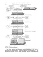
The proposed workflow of MPSoC software development is depicted in
Figure 8.1. The first step is to specify the application tasks with the pro-
posed parallel programming model, CIC. As shown in Figure 8.1, there are
two ways of generating a CIC program: One is to manually write the CIC
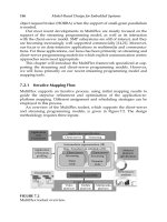
program, which is assumed in this chapter. The other is to generate the CIC
program from an initial model-based specification such as a dataflow model
or UML. Recently, it has become more popular to use a model driven archi-
tecture (MDA) for the systematic design of software (Balasubramanian et
al. [12]). In an MDA, system behavior is described in a platform-independent
model (PIM). The PIM is translated to a platform-specific model (PSM) from
which the target software on each processor is generated. The MDA method-
ology is expected to improve the design productivity of embedded software
since it increases the reuse possibilities of platform-independent software
modules: The same PIM can be reused for different target architectures.
Unlike other model-driven architectures, the unique feature of the pro-
posed methodology is to allow multiple PIMs in the programming frame-
work. We define an intermediate programming model common to all PIMs
including the manual design. Consequently, this programming model is
named CIC. The CIC is independent of the target architecture so that we
KPN
UML
Dataflow model
Automatic code generation Manual coding
Common intermediate code
Task codes(algorithm) XML file(architecture)
Task mapping
CIC translation
Target-executable C code
Virtual prototyping system
Performance lib./constraints
FIGURE 8.1
The proposed framework of software generation from CIC.
Nicolescu/Model-Based Design for Embedded Systems 67842_C008 Finals Page 212 2009-10-14
212 Model-Based Design for Embedded Systems
may explore the design space at a later stage of design. The CIC program
consists of two sections, a task code section and an architecture section.
The next step is to map task codes to processing components, manu-
ally or automatically. The optimal mapping problem is beyond the scope
of this chapter, so we assume that the mapping is somehow given. We are
now developing an optimal mapping technique based on a genetic algo-
rithm, considering three kinds of parallelisms simultaneously: functional
parallelism, data (loop) parallelism, and temporal parallelism.
The last step is to translate the CIC program into the target-executable
C codes based on the mapping and architecture information. In case more
than one task is mapped to the same processor, the CIC translator should
generate the run-time kernel that schedules the mapped tasks, or let the OS
schedule the mapped tasks to satisfy the real-time constraints of the tasks.
The CIC translator also synthesizes the interface codes between processing
components optimally for the given communication architecture.
8.4 Common Intermediate Code
The heart of the proposed design methodology is the CIC parallel program-
ming model that separates algorithm specification from architecture infor-
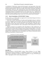
mation. Figure 8.2a displays the CIC format consisting of the two sections
that are explained in this section.
8.4.1 Task Code
A CIC task is a concurrent process that communicates with the other tasks
through channels as shown in Figure 8.2b. The “task code” section contains
Architecture
information
Task code
Hardware
Constraints
Structure
_init()
_go()
_wrapup()
(a)
(b)
Task Task
Port Port
Channel
Data
Ring queue
(c)
1. void task_init() { }
2.
int task_go(){
3.
MQ_RECEIVE(port_id, buf, size); //API for access channel4.
6. #pragma hardware IDCT ( ) { // HW pragma
/* code segment for IDCT */7.
}8.
#pragma omp //OpenMP directive for data-parallelism9.
{/* data parallel code */}10.
11.
12. }
void task_wrapup() { }13.
5. READ(file, data, 100); //Generic API for file read
FIGURE 8.2
Common intermediate code: (a) structure, (b) default intertask communica-
tion model, and (c) an example of a task code file.
Nicolescu/Model-Based Design for Embedded Systems 67842_C008 Finals Page 213 2009-10-14
Retargetable, Embedded Software Design Methodology 213
the definitions of CIC tasks that will be mapped to processing components
as a unit. An application is partitioned into tasks that represent the poten-
tial temporal and functional parallelism. Data, or loop, parallelism is defined
inside a task. It is the programmer’s decision as to how to define the tasks: As
the granularity of a task becomes finer, it will provide more potential for the
optimal exploitation of pipelining and functional parallelism at the expense
of increasing the burden of the programmer. An intuitive solution is to define
a task as reusable for other applications. Such a trade-off should be consid-
ered if a CIC is automatically generated from a model-based specification.
Figure 8.2c shows an example of a task–code file (.cic file) that defines
a task in C. A task should define three functions: {task name}_init(), {task
name}_go(), and {task name}_wrapup(). The {task name}_init() function
is called once when the task is invoked to initialize the task. The {task
name}_go() function defines the main body of the task and is executed
repeatedly in the main scheduling loop. The “{task_name}_wrapup()” func-
tion is called before stopping the task to reclaim the allocated resources.
The default channel is a FIFO channel, which is particularly adequate for
streaming applications. For target-independent specification, the CIC uses
generic APIs: For instance, two generic send–receive APIs are used for inter-
task communication as shown in Figure 8.2c, lines 4 and 5. The CIC translator
translates the generic API with the appropriate implementations, depending
on whether an OS is used or not. By doing so, the same task code will be
reused despite architecture variation.
There exist other types of channels among which an array channel is
defined to support wave-front parallelism [13]. The producer or the con-
sumer accesses the array channel with an index to the array element.
For single-writer-multiple-reader type of communication, a shared memory
channel is used.
An example of task specification is shown in Figure 8.3 where an H.263
decoder algorithm is partitioned into six tasks. In this figure, a macroblock
decoding task contains three functions: “Dequantize,” “Inverse zigzag,” and
“IDCT.” These three functions may be mapped to separate processors only
0
1
4
5
2
3
Variable
length
decoding
Macroblock
decoding Y
Macroblock
decoding U
Macroblock
decoding V
Motion
compensation
Display
frame
Inverse
zigzag
Dequantize IDCT
FIGURE 8.3
Task specification example: H.263 decoder. (From Kwon, S. et al., ACM Trans.
Des. Autom. Electron. Syst., 13, Article 39, July 2008. With permission.)
Nicolescu/Model-Based Design for Embedded Systems 67842_C008 Finals Page 214 2009-10-14
214 Model-Based Design for Embedded Systems
if they are specified as separate tasks in the CIC. Note that data parallelism
is specified with OpenMP directives within a task code, as shown at line 9 of
Figure 8.2c.
If there are HW accelerators in the target platform, we may want to use
them to improve the performance. To open this possibility in a task code, we
define a special pragma to identify the code section that can be mapped to
the HW accelerator, as shown in line 6 of Figure 8.2c. Moreover, information
on how to interface with the HW accelerator is specified in an architecture
information file. Then, the code segment contained within a pragma sec-
tion will be replaced with the appropriate HW-interfacing code by the CIC
translator.
8.4.2 Architecture Information File
The target architecture and design constraints are separately specified from
the task code in the architecture information section. The architecture sec-
tion is further divided into three sections in an xml-style file, as shown in
Figure 8.4. The “hardware” section contains the hardware architecture
information necessary to translate target-independent task codes to target-
dependent codes. The “constraints” section specifies user-specified con-
straints such as the real-time constraints, resource limitations, and energy
constraints. The “structure” section describes the communication and syn-
chronization requirements between tasks.
The hardware section defines the processor id, the address range and
size of each memory segment, use of OS, and the task scheduling policy
Architecture specification
Arm926ej-s
LM
SM
HW
Algorithm specification
100 ns
200 ns
Event
driven
Memory < 256 KB
Architecture information file
Hardware
Processor lists
Memory map
Hardware accelerators
OS support
Constraint
Structure
Memory constraint
Power constraint
Deadline per each task
Task structure
Communication channel
Processor mapping
Power < 16 mW
FIGURE 8.4
Architecture information section of a CIC consisting of three subsections that
define HW architecture, user-given constraints, and task structure.
Nicolescu/Model-Based Design for Embedded Systems 67842_C008 Finals Page 215 2009-10-14
Retargetable, Embedded Software Design Methodology 215
for each processor. For shared-memory segments, it indicates which pro-
cessors share the segment. It also defines information of hardware acceler-
ators, which includes architectural parameters and the translation library of
HW-interfacing code.
The constraints section defines the global constraints such as power con-
sumption and memory requirement as well as per task constraints such as
period, deadline, and priority. Further, it includes the execution time of tasks.
Using this set of information, we will determine the scheduling policies of the
target OS or synthesize the run-time system for the processor without OS.
In the structure section, task structure and task dependency are specified.
An application task usually consists of multiple tasks that are defined sepa-
rately in the task–code section of the CIC. The task structure is represented
by communication channels between the tasks.
For each task, the structure section defines the file name (with “.cic” suf-
fix) of the task code, and its compile options needed for compilation. More-
over, each task has the index field of the processor to which the task is
mapped. This field is updated after the task-mapping decision is made: In
other words, task mapping can be changed without modifying the task code,
but by changing the processor-mapping id of each task.
8.5 CIC Translator
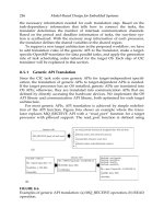
The CIC translator translates the CIC program into optimized executable
C codes for each processor core. As shown in Figure 8.5, the CIC transla-
tion consists of four main steps: generic API translation, HW-interface code
generation, OpenMP translation if needed, and task-scheduling code gen-
eration. From the architecture information file, the CIC translator extracts
Task codes (algorithm) XML file (architecuture info.)
Generic API translation
HW interface code generation
Is openMP compiler available?
No
OpenMP translation (target specific)
Task scheduling code generation
Target dependent parallel code
Yes
FIGURE 8.5
The workflow of a CIC translator.

