Equations of motion in the state and confiruration spaces pptx
Bạn đang xem bản rút gọn của tài liệu. Xem và tải ngay bản đầy đủ của tài liệu tại đây (4.73 MB, 165 trang )
z
Equations of motion in the state and
confiruration spaces
Appendix A
EQUATIONS OF MOTION
IN THE STATE
AND CONFIGURATION SPACES
A.1 EQUATIONS OF MOTION OF DISCRETE
LINEAR SYSTEMS
A.1.1 Configuration space
Consider a system with a single degree of freedom and assume that the equa-
tion expressing its dynamic equilibrium is a second order ordinary differential
equation (ODE) in the generalized coordinate x. Assume as well that the forces
entering the dynamic equilibrium equation are
• a force depending on acceleration (inertial force),
• a force depending on velocity (damping force),
• a force depending on displacement (restoring force),
• a force, usually applied from outside the system, that depends neither
on coordinate x nor on its derivatives, but is a generic function of time
(external forcing function).
If the dependence of the first three forces on acceleration, velocity and dis-
placement respectively is linear, the system is linear. Moreover, if the constants
of such a linear combination, usually referred to as mass m, damping coefficient
c and stuffiness k do not depend on time, the system is time-invariant. The
dynamic equilibrium equation is then
m¨x + c ˙x + kx = f(t) . (A.1)
666 Appendix A. EQUATIONS OF MOTION
If the system has a number n of degrees of freedom, the most general form
for a linear, time invariant set of second order ordinary differential equations is
A
1
¨x + A
2
˙x + A
3
x = f(t) , (A.2)
where:
• x is a vector of order n (n is the number of degrees of freedom of the
system) where the generalized coordinates are listed;
• A
1
, A
2
and A
3
are matrices, whose order is n ×n; they contain the char-
acteristics (independent of time) of the system;
• f is a vector function of time containing the forcing functions acting on the
system.
Matrix A
1
is usually symmetrical. The other two matrices in general are
not. They can be written as the sum of a symmetrical and a skew-symmetrical
matrices
M¨x +(C + G) ˙x +(K + H) x = f(t) , (A.3)
where:
• M,themass matrix of the system, is a symmetrical matrix of order n ×n
(coincides with A
1
). Usually it is not singular.
• C is the real symmetric viscous damping matrix (the symmetric part of
A
2
).
• K is the real symmetric stiffness matrix (the symmetric part of A
3
).
• G is the real skew-symmetric gyroscopic matrix (the skew-symmetric part
of A
2
).
• H is the real skew-symmetric circulatory matrix (the skew-symmetric part
of A
3
).
Remark A.1 Actually it is possible to write the set of linear differential Equa-
tions (A.2) in such a way that no matrix is either symmetric or skew symmetric
(it is enough to multiply one of the equations by a constant other than 1). A
better way to say this is that M, C,andK can be reduced to symmetric matrices
by the same linear transformation that reduces G and H into skew-symmetric
matrices.
Remark A.2 The same form of Equation (A.2) may result from mathematical
modeling of physical systems whose equations of motion are obtained by means of
space discretization techniques, such as the well-known finite elements method.
A.1 Equations of motion of discrete linear systems 667
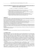
FIGURE A.1. Sketch of a system with two degrees of freedom (a) made by two masses
and two springs, whose characteristics (b) are linear only in a zone about the equilibrium
position. Three zones can be identified in the configuration space (c): in one the system
behaves linearily, in another the system is nonlinear. The latter zone is surrounded by
a ‘forbidden’ zone.
x is a vector in the sense it is a column matrix. Indeed, any set of n numbers
may be interpreted as a vector in an n-dimensional space. This space contain-
ing vector x is usually referred to as configuration space, because any point in
this space may be associated with a configuration of the system. Actually, not
all points of the configuration space, intended to be an infinite n-dimensional
space, correspond to configurations that are physically possible for the system:
It is then possible to define a subset of possible configurations. Moreover, even
systems that are dealt with using linear equations of motion are linear only for
configurations little displaced from a reference configuration (usually the equilib-
rium configuration) and thus the linear equation (A.2) applies in an even smaller
subset of the configuration space.
A simple system with two degrees of freedom is shown in Fig. A.1a; it consists
of two masses and two springs whose behavior is linear in a zone around the
equilibrium configuration with x
1
= x
2
= 0, but behave in a nonlinear way to
fail at a certain elongation. In the configuration space, which in the case of a
system with two degrees of freedom has two dimensions and thus is a plane, there
is a linearity zone, surrounded by a zone where the system behaves in nonlinear
way. Around the latter is another zone where the system loses its structural
integrity.
A.1.2 State space
Asetofn second order differential equations is a set of order 2n that can be
expressed in the form of a set of 2n first order equations.
668 Appendix A. EQUATIONS OF MOTION
In a way similar to above, a generic linear differential equation with constant
coefficients can be written in the form of a set of first order differential equations
A
1
˙x + A
2
x = f(t) . (A.4)
In system dynamics this set of equations is usually solved in the first deriva-
tives (monic form) and the forcing function is written as the linear combination
of the minimum number of functions expressing the inputs of the system. The
independent variables are said to be state variables and the equation is written
as
˙z = Az + Bu , (A.5)
where
• z is a vector of order m, in which the state variables are listed (m is the
number of the state variables);
• A is a matrix of order m × m, independent of time, called the dynamic
matrix;
• u is a vector function of time, where the inputs acting on the system are
listed (if r is the number of inputs, its size is r × 1);
• B is a matrix independent of time that states how the various inputs act
in the various equations. It is called the input gain matrix and its size is
m × r.
As was seen for vector x, z is also a column matrix that may be considered
as a vector in an m-dimensional space. This space is usually referred to as the
state space, because each point of this space corresponds to a given state of the
system.
Remark A.3 The configuration space is a subspace of the space state.
If Eq. (A.5) derives from Eq. (A.2), a set of n auxiliary variables must be
introduced to transform the system from the configuration to the state space.
Although other choices are possible, the simplest choice is to use the derivatives
of the generalized coordinates (generalized velocities) as auxiliary variables. Half
of the state variables are then the generalized coordinates x, while and the other
half are the generalized velocities ˙x.
If the state variables are ordered with velocities first and then coordinates,
it follows that
z =
˙x
x
.
A number n of equations expressing the link between coordinates and ve-
locities must be added to the n
equations (A.2). By using symbol v for the
A.1 Equations of motion of discrete linear systems 669
generalized velocities ˙x, and solving the equations in the derivatives of the state
variables, the set of 2n equations corresponding to Eq. (A.3) is then
˙v = −M
−1
(C + G) v − M
−1
(K + H) x + M
−1
f(t)
˙x = v .
(A.6)
Assuming that inputs u coincide with the forcing functions f, matrices A
and B are then linked to M,C, K, G and H by the following relationships
A =
−M
−1
(C + G) −M
−1
(K + H)
I0
, (A.7)
B =
M
−1
0
. (A.8)
The first n out of the m =2n equations constituting the state equation
(A.5) are the dynamic equilibrium equations. These are usually referred to as
dynamic equations. The other n express the relationship between the position
and the velocity variables. These are usually referred to as kinematic equations.
Often what is more interesting than the state vector z is a given linear
combination of states z and inputs u, usually referred to as the output vector.
The state equation (A.5) is then associated with an output equation
y = Cz + Du , (A.9)
where
• y is a vector where the output variables of the system are listed (if the
number of outputs is s, its size is s × 1);
• C is a matrix of order s × m, independent of time, called the output gain
matrix;
• D is a matrix independent of time that states how the inputs enter the
linear combination yielding the output of the system. It is called the direct
link matrix and its size is s ×r. In many cases the inputs do not enter the
linear combination yielding the outputs, and D is nil.
The four matrices A, B, C and D are usually referred to as the quadruple
of the dynamic system.
Summarizing, the equations that define the dynamic behavior of the system,
from input to output, are
˙z = Az + Bu
y = Cz + Du.
(A.10)
Remark A.4 While the state equations are differential equations, the output
equations are algebraic. The dynamics of the system is then concentrated in the
former.
The input-output relationship described by Eq. (A.10) may be described by
the block diagram shown in Fig. A.2.
670 Appendix A. EQUATIONS OF MOTION
FIGURE A.2. Block diagram corresponding to Eq. (A.10).
A.2 STABILITY OF LINEAR DYNAMIC SYSTEMS
The linearity of a set of equations allows one to state that a solution exists and is
unique. The general solution of the equation of motion is the sum of the general
solution of the homogeneous equation associated with it and a particular solution
of the complete equation. This is true for any differential linear set of equations,
even if it is not time-invariant.
The former is the free response of the system, the latter the response to the
forcing function.
Consider the equation of motion written in the configuration space (A.2).
As already stated, matrix A
1
is symmetrical, while the other two may not be.
The homogeneous equation
A
1
¨x(t)+A
2
˙x(t)+A
3
x(t) = 0 (A.11)
describes the free motion of the system and allows its stability to be studied.
The solution of Eq. (A.11) may be written as
x(t)=x
0
e
st
, (A.12)
where x
0
and s are a vector and a scalar, respectively, both complex and constant.
To state the time history of the solution allows the differential equation to be
transformed into an algebraic equation
A
1
s
2
+ A
2
s + A
3
x
0
= 0 . (A.13)
This is a set of linear algebraic homogeneous equations, whose coefficients
matrix is a second order lambda matrix
1
; it is square and, because the mass
matrix A
1
= M is not singular, the lambda matrix is said to be regular.
1
The term lambda matrix comes from the habit of using the symbol λ for the coefficient
appearing in the solution q(t)=q
0
e
λt
.Heresymbols has been used instead of λ, following a
more modern habit.
A.2 Stability of linear dynamic systems 671
The equation of motion (A.11) has solutions different from the trivial
x
0
= 0 (A.14)
if and only if the determinant of the matrix of the coefficients vanishes:
det
A
1
s
2
+ A
2
s + A
3
= 0 . (A.15)
Equation (A.15) is the characteristic equation of a generalized eigenproblem.
Its solutions s
i
are the eigenvalues of the system and the corresponding vectors
x
0
i
are its eigenvectors. The rank of the matrix of the coefficients obtained in
correspondence of each eigenvalue s
i
defines its multiplicity: If the rank is n−α
i
,
the multiplicity is α
i
. The eigenvalues are 2n and, correspondingly, there are 2n
eigenvectors.
A.2.1 Conservative natural systems
If the gyroscopic matrix G is not present the system is said to be natural.Ifthe
damping and circulatory matrices C and H also vanish the system is conserva-
tive. A system with G = C = H = 0 (or, as is usually referred to, an MK system)
is then both natural and conservative. The characteristic equation reduces to the
algebraic equation
det
Ms
2
i
+ K
= 0 . (A.16)
The eigenproblem can be reduced in canonical form
Dx
i
= μ
i
x
i
, (A.17)
where the dynamic matrix in the configuration space D (not to be confused with
the dynamic matrix in the state space A)is
D = M
−1
K , (A.18)
and the parameter in which the eigenproblem is written is
μ
i
= −s
2
i
. (A.19)
Because matrices M and K are positive defined (or, at least, semi-defined), the
n eigenvalues μ
i
are all real and positive (or zero) and then the eigenvalues in
terms of s
i
are 2n imaginary numbers in pairs with opposite sign
(s
i
, s
i
)=±i
√
μ
i
. (A.20)
The n eigenvectors x
i
of size n are real vectors.
When the eigenvalue s
i
is imaginary, the solution (A.12) reduces to an un-
damped harmonic oscillation
x(t)=x
0
e
iωt
, (A.21)
672 Appendix A. EQUATIONS OF MOTION
where
ω = is =
√
μ (A.22)
is the (circular) frequency.
The n values of ω
i
, computed from the eigenvalues μ
i
, are the natural fre-
quencies or eigenfrequencies of the system, usually referred to as ω
n
i
.
If M or K are not positive defined or semidefined, at least one of the eigen-
values μ
i
is negative, making one of the pair of solutions in s real, being made of
a positive and a negative value. As will be seen below, the real negative solution
corresponds to a time history that decays in time in a non-oscillatory way, the
positive solution to a time history that increases in time in an unbounded way.
The system is then unstable.
A.2.2 Natural nonconservative systems
If matrix C does not vanish while G = H = 0, the system is still natural and
non-circulatory, but is no longer conservative.
The characteristic equation (A.15) cannot be reduced to an eigenproblem in
canonical form in the configuration space and the state space formulation must
be used.
The general solution of the homogeneous equation associated with Eq. (A.5)
is of the type
z = z
0
e
st
, (A.23)
where s is generally a complex number. Its real and imaginary parts are usually
indicated with symbols ω and σ
ω = (s)
σ = (s)
(A.24)
and represent the frequency of the free oscillations and the decay rate. Solution
(A.23) can in fact be written in the form
z = z
0
e
σt
e
iωt
, (A.25)
or, because both σ and ω are real numbers,
z = z
0
e
σt
[cos (ωt)+i sin (ωt)] . (A.26)
By introducing solution (A.23) into the homogeneous equation associated
with Eq. (A.5), the latter transforms from a set of differential equations to a
(homogeneous) set of algebraic equations
sz
0
= Az
0
, (A.27)
i.e.
(A−sI) z
0
=0. (A.28)
A.2 Stability of linear dynamic systems 673
As seen for the equation of motion in the configuration space, the homoge-
neous equations will have solutions other than the trivial solution z
0
= 0 only if
the determinant of the coefficients matrix vanishes
det (A−sI)=0. (A.29)
Equation (A.29) can be interpreted as an algebraic equation in s, i.e. the
characteristic equation of the dynamic systems. It is an equation of power 2n,
yielding the 2n values of s. The 2n values of s are the eigenvalues of the system
and the corresponding 2n values of z
0
are the eigenvectors. In general, both
eigenvalues and eigenvectors are complex.
If matrix A is real, as is usually the case, the solutions are either real or
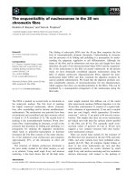
complex conjugate. The corresponding time histories are (Fig. A.3):
• Real solutions (ω =0,σ= 0): Either exponential time histories, with
monotonic decay of the amplitude if the solution is negative (stable, non-
oscillatory behavior), or exponential time histories, with monotonic in-
crease of the amplitude if the solution is positive (unstable, non-oscillatory
behavior).
• Complex conjugate solutions (ω =0,σ= 0): Oscillating time histories,
expressed by Eq. (A.26) with amplitude decay if the real part of the solution
FIGURE A.3. Time history of the free motion for the various types of the eigenvalues
of the system
674 Appendix A. EQUATIONS OF MOTION
is negative (stable, oscillatory behavior) or amplitude increase in time if
the real part of the solution is positive (unstable, oscillatory behavior). If
the system is stable, stability is asymptotic.
To these two cases, that previously seen for conservative systems may be
added:
• Imaginary solutions (ω =0,σ= 0): Harmonic time histories (sine or
cosine waves, undamped oscillatory behavior). In this case stability is non-
asymptotic.
The necessary and sufficient condition for stable behavior is thus that the
real part of all eigenvalues is negative.
If any one of the real parts of the eigenvalues is zero, the behavior is still
stable (because the amplitude does not grow uncontrolled in time) but not as-
ymptotically stable.
If at least one of the real parts of the eigenvalues is positive, the system is
unstable.
If the system is little damped, i.e. the eigenvalues are conjugate and the
decay rates σ are small, the values of the natural frequencies ω are close to those
of the corresponding undamped system, i.e. to those of the MK system obtained
by simply neglecting the damping matrix C. In this case the natural frequencies
ω
n
i
are still those of the corresponding undamped systems.
The general solution of the homogeneous equation is a linear combination
of the 2n solutions
z =
2n
i=1
C
i
z
0i
e
s
i
t
, (A.30)
where the 2n constants C
i
must be obtained from the initial conditions, i.e. from
vector z(0).
The equation allowing constants C
i
to be computed can be written as
z(0)=
z
01
z
02
z
02n
⎧
⎪
⎪
⎨
⎪
⎪
⎩
C
1
C
2
C
2n
⎫
⎪
⎪
⎬
⎪
⎪
⎭
= ΦC , (A.31)
where Φ is the matrix of the complex eigenvectors.
A real and negative eigenvalue corresponds to an overdamped behavior,
which is non-oscillatory, of the relevant mode. If the eigenvalue is complex (with
negative real part) the mode has an underdamped behavior, i.e. has a damped
oscillatory time history. A system with all underdamped modes is said to be
underdamped, while if only one of the modes is overdamped, the system is said
to be overdamped. If all modes are overdamped, the system cannot have free
oscillations, but can oscillate if forced to do so.
It must be noted that if all matrices M, K and C are positive defined (or
at least semidefined), as in the case of a structure with viscous damping with
A.2 Stability of linear dynamic systems 675
positive stiffness and damping, there is no eigenvalue with positive real part and
hence the system is stable. If all matrices are strictly positive defined, there is
no eigenvalue with vanishing real part and the system is asymptotically stable.
A.2.3 Systems with singular mass matrix
If matrix M is singular, it is impossible to write the dynamic matrix in the usual
way. This usually occurs because a vanishingly small inertia is associated with
some degrees of freedom, as for instance in the case of the driveline models shown
in Fig. 30.9, where the tire is modelled as a spring and a damper in series, with
no mass between them. Clearly the problem may be circumvented by associating
a very small mass with the relevant degrees of freedom: A new very high natural
frequency that has no physical meaning is thus introduced and, if this is done
carefully, no numerical instability problem results. However, it makes little sense
to resort to tricks of this kind when it is possible to overcome the problem in a
more correct and essentially simple way.
The degrees of freedom can be subdivided into two sets: A vector x
1
con-
taining those with which a non-vanishing inertia is associated, and a vector x
2
,
containing all others. All matrices and forcing functions may be similarly split
. The mass matrix M
22
vanishes, and if the mass matrix is diagonal, M
12
and
M
21
also vanish.
Assuming that M
12
and M
21
are zero, the equations of motion become
M
11
¨x
1
+ C
11
˙x
1
+ C
12
˙x
2
+ K
11
x
1
+ K
12
x
2
= f
1
(t)
C
21
˙x
1
+ C
22
˙x
2
+ K
21
x
1
+ K
22
x
2
= f
2
(t).
(A.32)
To simplify the equations of motion neither the gyroscopic nor the circu-
lator matrices are explicitly written, but in what follows no assumption on the
symmetry of the stiffness and damping matrices will be made. The equations
also hold for gyroscopic and circulatory systems.
By introducing the velocities v
1
together with generalized coordinates x
1
and x
2
as state variables, the state equation is
M
∗
⎧
⎨
⎩
v
1
x
1
x
2
⎫
⎬
⎭
= A
∗
⎧
⎨
⎩
v
1
x
1
x
2
⎫
⎬
⎭
+
⎡
⎣
I0
0I
00
⎤
⎦
f
1
(t)
f
2
(t)
, (A.33)
where
M
∗
=
⎡
⎣
M
11
0C
12
00C
22
0I0
⎤
⎦
, A
∗
= −
⎡
⎣
C
11
K
11
K
12
C
21
K
21
K
22
−I0 0
⎤
⎦
. (A.34)
The dynamic matrix and the input gain matrix are
A = M
∗−1
A
∗
, B = M
∗−1
⎡
⎣
I0
0I
00
⎤
⎦
. (A.35)
676 Appendix A. EQUATIONS OF MOTION
Alternatively, the expressions of M
∗
and A
∗
can be
M
∗
=
⎡
⎣
M
11
C
11
C
12
0C
21
C
22
0I0
⎤
⎦
, A
∗
= −
⎡
⎣
0K
11
K
12
0K
21
K
22
−I0 0
⎤
⎦
. (A.36)
If vector x
1
contains n
1
elements and x
2
contains n
2
elements, the size of
the dynamic matrix A is 2n
1
+ n
2
.
A.2.4 Conservative gyroscopic systems
If matrix G is not zero, while both C and H vanish, the dynamic matrix reduces
to
A =
−M
−1
G −M
−1
K
I0
. (A.37)
By premultiplying the first n equations by M and the other n by K,it
follows that
M
∗
˙z + G
∗
z = 0 , (A.38)
where
M
∗
=
M0
0K
, G
∗
=
GK
−K0
. (A.39)
The first matrix is symmetrical, while the second is skew symmetrical.
By introducing solutions (A.23) into the equation of motion, the following
homogeneous equation
sM
∗
z
0
+G
∗
z
0
= 0 (A.40)
is obtained.
The corresponding eigenproblem has imaginary solutions like those of an
MK system, even if the structure of the eigenvectors is different. In any case
the time history of the free oscillations is harmonic and undamped, because the
decay rate σ = (s) is zero.
A.2.5 General dynamic systems
The situation is similar to that seen for natural non-conservative systems, in the
sense that the time histories of the free oscillations are those seen in Fig. A.3 and
stability is dominated by the sign of the real part of s.
Remark A.5 In general, the presence of a gyroscopic matrix does not reduce
the stability of the system, while the presence of a circulatory matrix has a desta-
bilizing effect.
A.2 Stability of linear dynamic systems 677
Consider, for instance, a two degrees of freedom system made by two inde-
pendent MK system; each with a single degree of freedom, and assume that the
two masses are equal. The equations for free motion are
m¨x
1
+ k
1
x
1
=0
m¨x
2
+ k
2
x
2
=0.
(A.41)
Introduce now a coupling term in both equations, introducing for instance
a spring with stiffness k
12
between the two masses. The equations of motion
become
m¨x
1
+(k
1
+ k
12
) x
1
− k
12
x
2
=0,
m¨x
2
− k
12
x
1
+(k
1
+ k
12
) x
2
=0.
(A.42)
By introducing parameters
ω
2
0
=
k
1
+ k
2
+2k
12
2m
, α =
k
2
− k
1
2mΩ
2
0
, =
k
12
mΩ
2
0
, (A.43)
the equation of motion can be written as
¨x
¨y
+ ω
2
0
1 − α
1+α
x
y
= 0 . (A.44)
Note that
−1 ≤ α ≤ 1 . (A.45)
The matrix that multiplies the generalized coordinates is symmetrical and is
thus a true stiffness matrix. The coupling is said in this case to be non-circolatory
or conservative. Because there is no damping matrix and the stiffness matrix is
positive defined (−1 ≤ α ≤ 1), the eigenvalues are imaginary and the system is
stable, even if it is not asymptotically stable as it would be if a positive defined
damping matrix were present.
The natural frequencies of the system, made nondimensional by dividing
them by ω
0
, depend upon two parameters, α and . They are shown in Fig. A.4(a)
as functions of α for some values of . The distance between the two curves (one
for ω>ω
0
and the other for ω<ω
0
) increases if the coupling term increases.
For this reason this type of coupling is said to be repulsive.
Consider now the case with coupling term in the form
¨x
¨y
+Ω
2
0
1 − α
− 1+α
x
y
= 0 . (A.46)
The terms outside the main diagonal of the stiffness matrix now have the
same modulus but opposite sign. The matrix multiplying the displacements is
made up of a symmetrical part (the stiffness matrix) and a skew-symmetrical
part (the circulatory matrix). A coupling of this type is said to be circulatory or
non-conservative.
While in the previous case the effect could be caused by the presence of a
spring between the two masses, it cannot be due to springs or similar elements
here. There are situations of practical interest where circulatory coupling occurs.
678 Appendix A. EQUATIONS OF MOTION
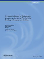
FIGURE A.4. Nondimensional natural frequencies as functions of parameters α and
for a system with two degrees of freedom with non-circulatory (a) and circulatory (b)
coupling. Decay rate (c) and roots locus (d) for the system with circulatory coupling.
The natural frequencies of the system in this case also depend on the two
parameters α and . These are plotted in nondimensional form, by dividing them
by ω
0
, in Fig. A.4(b) as functions of α for some values of . The two curves now
close on each other. Starting from the condition with α = −1, the two curves
meet for a certain value of α in the interval (−1, 0). There is a range, centered
in the point with α = 0, where the solutions of the eigenproblem are complex.
Beyond this range the two curves separate again.
Because the two curves approach each other and finally meet, this type of
coupling is said to be attractive.
In the range where the values of s are complex, one of the two solutions has
a positive real part: It follows that an unstable solution exists, as can be seen
from the decay rate plot in Fig. A.4(c) and from the roots locus in Fig. A.4(d).
Remark A.6 Instability is linked with the skew-symmetric matrix due to cou-
pling, i.e. because of the fact that a circulatory matrix exists.
A.3 Closed form solution of the forced response 679
A.3 CLOSED FORM SOLUTION OF THE FORCED
RESPONSE
The particular solution of the complete equation depends on the time history of
the forcing function (input) u (t). In case of harmonic input
u = u
0
e
iωt
, (A.47)
the response is harmonic as well
z = z
0
e
iωt
, (A.48)
and has the same frequency as the forcing function ω. As usual, by introducing
the time history of the forcing function and the response into the equation of
motion, it transforms into an algebraic equation
(A−iωI) z
0
+ Bu
0
=0, (A.49)
that allows the amplitude of the response to be computed
z
0
= −(A−iωI)
−1
Bu
0
. (A.50)
If the input is periodic, it may be decomposed in Fourier series and the
response to each of its harmonic components computed. The results are then
added. This is possible only because the system is linear.
If the input is not harmonic or at least periodic, it is possible to resort
to Laplace transforms or the Duhamel integral. These techniques apply only to
linear systems.
Remark A.7 Linear models allow closed form solutions to be obtained and sta-
bility, in particular, to be studied. In linear systems, moreover, stability is a
property of the system and not of its peculiar working conditions.
A.4 NONLINEAR DYNAMIC SYSTEMS
The state equations of dynamic systems are often nonlinear. The reasons for the
presence of nonlinearities may differ, owing to the presence of elements behaving
in an intrinsically nonlinear way (e.g. springs producing a force dependent in a
nonlinear way on the displacement), or the presence of trigonometric functions
of some of the generalized coordinates in the dynamic or kinematic equations.
If inertial forces are linear in the accelerations, the equations of motion can be
written in the form
M¨x + f
1
(x, ˙x)=f(t) . (A.51)
680 Appendix A. EQUATIONS OF MOTION
Function f
1
may often be considered as the sum of a linear and nonlinear
part. The equation of motion can then be written as
M¨x +(C + G) ˙x +(K + H) x + f
2
(x, ˙x)=f(t) , (A.52)
where function f
2
contains only the nonlinear part of the dynamic system.
The state equations corresponding to Eq. (A.51) and Eq. (A.52) are
˙z = f
1
(z)+Bu , (A.53)
or, by separating the linear from the nonlinear part,
˙z = Az + f
2
(z)+Bu . (A.54)
Another way to express the equation of motion or the state equation of
a nonlinear system is by writing equations (A.3) or (A.10), where the various
matrices are functions of the generalized coordinates and their derivatives, or of
the state variables. In the state space it follows that
˙z = A(z)z + B(z)u
y = C(z)z + D(z)u .
(A.55)
If the system is not time-invariant, the various matrices may also be explicit
functions of time
˙z = A(z,t)z + B(z,t)u
y = C(z,t)z + D(z,t)u .
(A.56)
Remark A.8 It is not possible to obtain a closed form solution of nonlinear
systems, and concepts like natural frequency or decay rate lose their meaning. It
is not even possible to distinguish between free and forced behavior, in the sense
that the free oscillations depend upon the zone of the state space where the system
operates.
In some zones of the state space the behavior of the system may be stable,
while in others it may be unstable.
In any case it is often possible to linearize the equations of motion about any
given working conditions, i.e. any given point of the state space, and to use the
linearized model so obtained in that area of the space state to study the motion
of the system and above all its stability. In this case the motion and stability are
studied in the small. It is, however, clear that no general result may be obtained
in this way.
If the state equation is written in the form (A.53), its linearization about a
point of coordinates z
0
in the state space is
˙z =
∂f
1
∂z
z=z
0
z + Bu , (A.57)
where
∂f
1
∂z
z=z
0
is the Jacobian matrix of function f
1
computed in z
0
.
A.5 Lagrange equations in the configuration and state space 681
If the formulation (A.55) is used, the linearized dynamics of the system
about point z
0
may be studied through the linear equation
˙z = A(z
0
)z + B(z
0
)u
y = C(z
0
)z + D(z
0
)u .
(A.58)
Remark A.9 While the motion and stability in the small can be studied in
closed form, studying the motion in the large requires resorting to the numerical
integration of the equations of motion, that is, resorting to numerical simulation.
A.5 LAGRANGE EQUATIONS IN THE
CONFIGURATION AND STATE SPACE
In relatively simple systems it is possible to write the equations of motion directly
in the form of Eq. (A.3), by writing all forces, internal and external to the system,
acting on its various parts. However, if the system is complex, and in particular if
the number of degrees of freedom is large, it is expedient to resort to the methods
of analytical mechanics.
One of the simplest approaches to writing the equations of motion of multi-
degrees of freedom systems is by resorting to Lagrange equations. Consider a
generic mechanical system with n degrees of freedom, i.e. one whose configuration
may be expressed using n generalized coordinates x
i
. Its equations of motion can
in general be written in the form
d
dt
∂T
∂ ˙x
i
−
∂T
∂x
i
+
∂U
∂x
i
+
∂F
∂ ˙x
i
= Q
i
(i = 1, , n), (A.59)
where:
•T is the kinetic energy of the system. This allows inertial forces to be
written in a synthetic way. In general,
T = T (˙x
i
,x
i
,t) .
The kinetic energy is basically a quadratic function of the generalized ve-
locities
T = T
0
+ T
1
+ T
2
, (A.60)
where T
0
does not depend on the velocities, T
1
is linear and T
2
is quadratic.
In linear systems, the kinetic energy must contain terms of the velocities
and coordinates having no powers higher than 2 or products of more than
two of them. As a consequence, T
2
cannot contain displacements
T
2
=
1
2
n
i=1
n
j=1
m
ij
x
i
x
j
=
1
2
˙
x
T
M
˙
x , (A.61)
where the terms m
ij
don’t depend on either x or
˙
x. If the system is time-
invariant, M is constant.
682 Appendix A. EQUATIONS OF MOTION
T
1
is linear in the velocities, and thus, if the system is linear, cannot contain
terms other than constant or linear in the displacements
T
1
=
1
2
˙
x
T
(M
1
x + f
1
) , (A.62)
where matrix M
1
and vector f
1
do not contain the generalized coordinates,
even if f
1
may be a function of time even in time-invariant systems.
T
0
does not contain generalized velocities but, in the case of linear sys-
tems, only contains terms with power not greater than 2 in the generalized
coordinates:
T
o
=
1
2
x
T
M
g
x + x
T
f
2
+e, (A.63)
where matrix M
g
, vector f
2
and scalar e are constant. Constant e does not
enter the equations of motion. As will be seen later, the structure of T
o
is
similar to that of the potential energy. The term
U−T
0
is often referred to as dynamic potential.
•Uis the potential energy. It allows conservative forces to be expressed in a
synthetic form. In general,
U = U(x
i
) .
In linear systems, the potential energy is a quadratic form in the general-
ized coordinates and, apart from a constant term that does not enter the
equations of motion and thus has no importance, can be written as
U =
1
2
x
T
Kx + x
T
f
0
, (A.64)
By definition the potential energy does not depend on the generalized ve-
locities and its derivatives with respect to the generalized velocities ˙x
i
vanish. Equation (A.59) is often written with reference to the Lagrangian
function
L = T−U
and becomes
d
dt
∂L
∂ ˙x
i
−
∂L
∂x
i
+
∂F
∂ ˙x
i
= Q
i
. (A.65)
•Fis the Raleigh dissipation function. It allows some types of damping
forces to be expressed in a synthetic form. In many cases F = F(˙x
i
), but
it may also depend upon the generalized coordinates. In linear systems, the
dissipation function is a quadratic form in the generalized velocities and,
apart from terms not depending upon ˙x
i
that do not enter the equation of
motion and thus have no importance, may be written as
F =
1
2
˙x
T
C˙x +
1
2
˙x
T
(C
1
x + f
3
) . (A.66)
A.5 Lagrange equations in the configuration and state space 683
• Q
i
are generalized forces that cannot be expressed using the above men-
tioned functions. In general, Q
i
= Q
i
(˙q
i
,q
i
,t). In the case of linear systems,
these forces do not depend on the generalized coordinates and velocities,
and then
Q
i
= Q
i
(t) . (A.67)
In linear systems, by performing the relevant derivatives
∂(T−U)
∂ ˙x
i
= M
˙
x +
1
2
(M
1
x + f
1
) , (A.68)
d
dt
∂(T−U)
∂ ˙x
i
= M
¨
x +
1
2
M
1
˙x +
˙
f
1
, (A.69)
∂(T−U)
∂x
i
=
1
2
M
T
1
˙
x + M
g
x − Kx + f
2
− f
0
, (A.70)
∂F
∂ ˙x
i
= C
˙
x + C
1
x + f
3
, (A.71)
the equation of motion becomes
M
¨
x+
1
2
M
1
−M
T
1
˙x+C
˙
x+(K−M
g
+ C
1
) x = −
˙
f
1
+ f
2
−f
3
−f
0
+Q . (A.72)
Matrix M
1
is normally skew-symmetric. However, even if it is not, it may
be written as the sum of a symmetrical and a skew-symmetrical part
M
1
= M
1symm
+ M
1skew
. (A.73)
By introducing this form into Eq. (A.72), the term
M
1
−M
T
1
becomes
M
1symm
+ M
1skew
− M
1symm
+ M
1skew
=2M
1skew
.
Only the skew-symmetric part of M
1
is included in the equation of motion.
C
1
is usually skew-symmetrical.
Writing M
1skew
as G and C
1
(or at least its skew-symmetric part; if a
symmetric part existed, it could be included into matrix K)asH, and including
vectors f
0
,
˙
f
1
, f
2
and f
3
into forcing functions Q, the equation of motion becomes
M
¨
x +(C + G) ˙x +(K−M
g
+ H) x = Q . (A.74)
The mass, stiffness, gyroscopic and circulatory matrices M, K, G and H
have already been defined. The symmetric matrix M
g
is often defined as a geo-
metric matrix
2
.
2
Here the symbol M
g
is used instead of the more common K
g
to emphasize that it comes
from the kinetic energy.
684 Appendix A. EQUATIONS OF MOTION
As already stated, a system in which T
1
is not present is said to be natural.
Its equation of motion does not contain a gyroscopic matrix. In many cases T
0
also is absent and the kinetic energy is expressed by Eq. (A.61).
The linearized equation of motion of a nonlinear system can be written in
two possible ways. The first is by writing the complete expression of the energies,
performing the derivatives obtaining the complete equations of motion and then
cancelling nonlinear terms.
The second is by reducing the expression of the energies to quadratic forms,
developing their expressions in power series and then truncating them after the
quadratic terms. The linearized equations of motion are then directly obtained.
Remark A.10 These two approaches yield the same result, but the first is usu-
ally more computationally intensive. At any rate, a set of n second order equa-
tions are obtained: These are either linear or nonlinear depending on the system
under study.
To write the state equations, a number n of kinematic equations must be
written
˙x
i
= v
i
(i = 1, , n). (A.75)
If the state vector is defined in the usual way
z =
v
x
,
this procedure is straightforward.
A.6 HAMILTON EQUATIONS AND PHASE SPACE
If the generalized momenta are used as auxiliary variables instead of the gener-
alized velocities, the equations are written with reference to the phase space and
phase vector instead of the state space and vector.
The generalized momenta are defined, starting from the Lagrangian L,as
p =
∂L
∂ ˙x
i
. (A.76)
If the system is a natural linear system, this definition reduces to the usual
one
p = M˙x . (A.77)
By including the forces coming from the dissipation function in the gener-
alized forces Q
i
, the Lagrange equation simplifies as
˙p
i
=
∂L
∂x
i
+ Q
i
. (A.78)
A.7 Lagrange equations in terms of pseudo coordinates 685
A function H(˙x
i
,x
i
,t), called the Hamiltonian function, is defined as
H = p
T
˙x−L . (A.79)
Because H is a function of p
i
, x
i
and t (H(p
i
,x
i
,t)), the differential δH is
δH =
n
i=1
∂H
∂p
i
δp
i
+
∂H
∂x
i
δx
i
. (A.80)
On the other hand, Eq. (A.79) yields
δH =
n
i=1
p
i
δ ˙x
i
+˙x
i
δp
i
−
∂L
∂x
i
δx
i
−
∂L
∂ ˙x
i
δ ˙x
i
= (A.81)
=
n
i=1
˙x
i
δp
i
−
∂L
∂x
i
δx
i
,
and then
∂H
∂p
i
=˙x
i
,
∂H
∂x
i
= −
∂L
∂x
i
. (A.82)
The 2n phase space equations are then
⎧
⎪
⎪
⎪
⎨
⎪
⎪
⎪
⎩
˙x
i
=
∂H
∂p
i
˙p
i
= −
∂H
∂x
i
+ Q
i
.
(A.83)
A.7 LAGRANGE EQUATIONS IN TERMS
OF PSEUDO COORDINATES
While in vehicle dynamics Hamilton equations are seldom used, the state equa-
tions are often written with reference to generalized velocities that are not simply
the derivatives of the generalized coordinates. In particular, it is often expedient
to use suitable combinations of the derivatives of the coordinates v
i
=˙x
i
as
generalized velocities
{w
i
} = A
T
{˙x
i
} , (A.84)
where the coefficients of the linear combinations included into matrix A
T
may
be constant, but in general are functions of the generalized coordinates.
Equation (A.84) may be inverted, obtaining
{˙x
i
} = B {w
i
} , (A.85)
686 Appendix A. EQUATIONS OF MOTION
where
B = A
−T
(A.86)
and symbol A
−T
indicates the inverse of the transpose of matrix A.
In some cases matrix A
T
is a rotation matrix whose inverse coincides with
its transpose. In such cases
B = A
−T
= A .
However, this generally does not occur and
B = A .
While v
i
are the derivatives of the coordinates x
i
, it is usually not possible
to express w
i
as the derivatives of suitable coordinates. Eq. (A.84) can be written
in the infinitesimal displacements dx
i
{dθ
i
} = A
T
{dx
i
} , (A.87)
obtaining a set of infinitesimal displacements dθ
i
, corresponding to velocities w
i
.
Equations (A.87) can be integrated, yielding displacements θ
i
corresponding to
the velocities w
i
, only if
∂a
js
∂x
k
=
∂a
ks
∂x
j
.
Otherwise equations (A.87) cannot be integrated and velocities w
i
cannot
be considered as the derivatives of true coordinates. In such cases they are said
to be the derivatives of pseudo-coordinates.
As a first consequence of the non-existence of coordinates corresponding to
velocities w
i
, Lagrange equation (A.59) cannot be written directly using veloci-
ties w
i
(which cannot be considered as derivatives of the new coordinates), but
must be modified to allow the use of velocities and coordinates that are not
direct derivatives of each other.
The use of pseudo-coordinates is fairly common, particularly in vehicle dy-
namics. If, for instance, the generalized velocities in a reference frame following
the body in its motion are used in the dynamics of a rigid body, while the coor-
dinates x
i
are the displacements in an inertial frame, matrix A
T
is simply the
rotation matrix allowing passage from one reference frame to the other. Matrix
B then coincides with A, but neither is symmetrical. The velocities in the body-
fixed frame cannot therefore be considered as the derivatives of the displacements
in that frame.
Remark A.11 The body-fixed frame rotates continuously so that it is not possi-
ble to integrate the velocities along the body-fixed axes to obtain the displacements
along the same axes. This fact notwithstanding, it is possible to use the compo-
nents of the velocity along the body-fixed axes to write the equations of motion.
The kinetic energy can be written in general in the form
T = T (w
i
,x
i
,t) .
A.7 Lagrange equations in terms of pseudo coordinates 687
The derivatives
∂T
∂ ˙x
i
included into the equations of motion are
∂T
∂ ˙x
k
=
n
i=1
∂T
∂w
i
∂w
i
∂ ˙x
k
, (A.88)
i.e., in matrix form,
∂T
∂ ˙x
= A
∂T
∂w
, (A.89)
where
∂T
∂ ˙x
=
∂T
∂ ˙x
1
∂T
∂ ˙x
2
T
,
∂T
∂w
=
∂T
∂w
1
∂T
∂w
2
T
.
By differentiating with respect to time, it follows that
∂
∂t
∂T
∂ ˙x
= A
∂
∂t
∂T
∂w
+
˙
A
∂T
∂w
, (A.90)
The generic element ˙a
jk
of matrix
˙
A is
˙a
jk
=
n
i=1
∂a
jk
∂x
i
˙x
i
= ˙x
T
∂a
jk
∂x
, (A.91)
and then
˙a
jk
= w
T
B
T
∂a
jk
∂x
. (A.92)
The various ˙a
jk
so computed can be written in matrix form
˙
A =
w
T
B
T
∂a
jk
∂x
. (A.93)
The computation of the derivatives of the generalized coordinates
∂T
∂x
is
usually less straightforward. The generic derivative
∂T
∂x
k
is
∂T
∗
∂x
k
=
∂T
∂x
k
+
n
i=1
∂T
∂w
i
∂w
i
∂x
k
=
∂T
∂x
k
+
n
i=1
∂T
∂w
i
n
j=1
∂a
ij
∂x
k
˙x
j
, (A.94)
where T
∗
is the kinetic energy expressed as a function of the generalized coor-
dinates and their derivatives (the expression to be introduced into the Lagrange
equation in its usual form), while T is expressed as a function of the generalized
688 Appendix A. EQUATIONS OF MOTION
coordinates and of the velocities in the body-fixed frame. Equation (A.94) can
be written as
∂T
∗
∂x
k
=
∂T
∂x
k
+ w
T
B
T
∂A
∂x
k
∂T
∂w
, (A.95)
where product w
T
B
T
∂A
∂x
k
yields a row matrix with n elements, which multiplied
by the column matrix
∂T
∂w
yields the required number.
By combining these row matrices, a square matrix is obtained
w
T
B
T
∂A
∂x
k
, (A.96)
and then the column containing the derivatives with respect to the generalized
coordinates is
∂T
∗
∂x
=
∂T
∂x
+
w
T
B
T
∂A
∂x
∂T
∂w
. (A.97)
By definition, the potential energy does not depend on the generalized ve-
locities. Thus the term
∂U
∂x
i
is not influenced by the way the generalized velocities
are written. Finally, the derivatives of the dissipation function are
∂F
∂ ˙x
= A
∂F
∂w
(A.98)
The equation of motion (A.59) is then
A
∂
∂t
∂T
∂w
+ Γ
∂T
∂w
−
∂T
∂x
+
∂U
∂x
+ A
∂F
∂w
= Q , (A.99)
where
Γ =
w
T
B
T
∂a
jk
∂x
−
w
T
B
T
∂A
∂x
k
(A.100)
and Q is a vector containing the n generalized forces Q
i
.
By premultiplying all terms by matrix B
T
= A
−1
and attaching the kine-
matic equations to the dynamic equations, the final form of the state space
equations is obtained
⎧
⎪
⎪
⎨
⎪
⎪
⎩
∂
∂t
∂T
∂w
+ B
T
Γ
∂T
∂w
− B
T
∂T
∂x
+ B
T
∂U
∂x
+
∂F
∂w
= B
T
Q
{˙q
i
} = B {w
i
} .
(A.101)