Scalable voip mobility intedration and deployment- P36 ppsx
Bạn đang xem bản rút gọn của tài liệu. Xem và tải ngay bản đầy đủ của tài liệu tại đây (1.38 MB, 10 trang )
The Future: Video Mobility and Beyond 351
www.newnespress.com
pixels in the device’s display, as there is not much sense in using a video stream that has a
higher resolution than the display.
Each pixel holds the color information for that pixel. This makes a pixel a rectangular area
of uniform color. Computer representations of human-visible color can be measured in
many different ways—which is both a problem and an opportunity. For raw images, which
have no compression, one common way to measure color is to use the RGB method. RGB
relies on how the human eye can see three primary colors—red, green, and blue—and that
all colors are some combination of those three. For this reason, computer and television
displays are made with pixels that are themselves made of the three different colors, each lit
with independent intensity. The perception of color is a rich and detailed subject, but there
are some concepts to it that we should briefly address here to give a sense for what is going
on. Pure light, as electromagnetic radiation, can be thought of as having one frequency. The
colors of the rainbow are all colors of one pure “tone,” or light of one single frequency.
The eye has cones, the receptors that show color, and these cones come in three types, not
surprisingly one for red, one for blue, and one for green. The three cones will respond
differently for each pure, spectral color, giving the eye good coverage over all of the colors
that can exist in the world. When light of one frequency falls upon the cones of the eye,
each type cone responds differently and predictably. From this comes the perception of the
color of that frequency.
Of course, not all colors are made of pure color. White is most certainly not a pure color, as
it is able to be split by a prism into the entire rainbow spectrum. It must be more than just
one frequency, then. In fact, it is a balanced mixture of many frequencies, and comes out
white because it is able to excite the three primary color cones the eye sees with even
intensity. This is no coincidence, as while happens to represent the total mixture of
frequencies the sun radiates down on the planet. Because everything we see is reflected
from normally white light, our most common experiences of colors have to belong to the
subset of white light itself.
We can think of representing color by, then, a triplet of intensities, representing the amount
of activation of the three cones in the eye. This is a good start. As it happens, however,
video displays are not built around the exact excitement of the three cones. The red, blue,
and green are a bit different than what the eye sees, mostly because display screens need to
generate light from something that could be mass produced, and it was sufficient to use a
different red, green, and blue, so long as the entire range of colors could get close to
running the gamut of what the eye can see. (Gamut is the correct term for the space of
colors that a particular way of representing colors can cover.) This means that RGB can
represent essentially all of the colors we know of and use on a regular basis, though often
as only an approximation to the real thing. There are some colors in nature that can never
be seen on a screen—often those that are the most vibrant.
352 Chapter 9
www.newnespress.com
However, we can still get a sense of how the primary RGB colors of light add up. Red and
blue readily mix to form purple, which is easy to describe as a reddish-blue hue. Blue and
green mix to form a blue-green color, such as cyan. The odd one is red and green together,
which produces yellow, a color most people would not describe with the term red-green,
being a pair of colors which seem as opposite as can be imagined. (It is difficult to imagine
that the two colors of a poinsettia can ever combine to form the color of a banana.) All
three together form white, and all three absent form black. Staring at any screen up close
will show exactly how this process works in video displays to blend together to form a
color, as each pixel is made of subpixels, or regions of only one color, that can only vary by
intensity. When viewed from a reasonable distance, the eye does not do a good job seeing
the separate subpixels, and so it blends the three different hues together to form the final,
intended, color.
In computer displays, the widely-used sampling method is to given each primary color an
intensity of eight bits, producing a 24-bit overall color sample per pixel. This lets us step back
and look at the size of video. Compared to raw voice, which must encode only one 16-bit
sample at a given time, raw video must encode hundreds of thousands of 24-bit color samples.
Even though the number of times a second the set of pixels, the picture known as a frame is far
less—the size of a frame quickly dominates. On standard video, the picture (and thus pixel
color intensities) changes up to 30 times a second, far less often than the 8000 times a second
that the voice intensity changes. Multiplying it out, a raw voice stream requires 128,000 bits a
second; a raw 640×480 video at 30 frames per second requires 221,184,000 bits per second for
just the video portion, not including any associated audio streams.
9.1.2 Video Compression
The large size of video clearly begs for compression. Fortunately, much of the detail in
video is wasted on the viewer, and video has a tremendous amount of room for lossy
compression to be employed. Video compression is an area of active research, but the basics
are easy to understand, and are used in modern compression algorithms, such as those for
MPEG video.
9.1.2.1 Still Image Compression
The first area we can look to compress video is with the representation of color. Many of
you who may read this book may also remember how color digital displays evolved, and
thus would have a natural understanding of how excessive 16,777,216 possible colors per
pixel once seemed. However, it does bear repeating. The eye can be challenged, by certain
color transitions, or changes of color from one to the next, to need all 24 bits to capture
most of the range of differences the eye can see. But, ignoring those specific, challenging
situations, the eye can really see only a few thousand colors. Furthermore, if exact color
reproduction is not the point—and it is not, for video—making minor approximations here
The Future: Video Mobility and Beyond 353
www.newnespress.com
or there is quite acceptable. Therefore, the first technique for video compression is to
radically reduce the number of colors, following the usual media compression technique of
focusing the bits to where they are most perceivable by the human observer, and then filling
in the details with bits that may not be kept or can be afforded to be lost.
Although the red, green, and blue representation works quite well for representing what the
video display needs to do, it is not the most obvious choice for representing human-
perceived color. We can take a hint from the development of analog television. Intensity—
the overall intensity of the pixel—matters the most. Thus, black and white works quite well
for representing the subject of the video, so long as people are not dressed with garish
colors that would go missed. Because intensity is so important, representing the intensity is
the best use of the bits of information for a pixel. Once the black-and-white intensity is
known, the remaining bits can be used to give the shade of pixel a tint, or hue. Three
primary colors mean three additional hue values, right? Thankfully not. If we think of color
as a mathematical vector of three dimensions, knowing the intensity is like knowing the
length. We only need to know how far the color extends into two of the three dimensions,
along with the length, to get the intended color back out. (This is embedded in the very
definition of having three dimensions to color.) The two choices that television designers
settled on was to record both how red and how blue the color is, leaving green to be
inferred. It starts with an intensity, also known as a luminance in this representation, such as
highest for white and lowest for black. The tinting, using the two chrominances, each add
or subtract an amount of the primary color they represent. Together, the luminance and two
chrominances create another 24-bit value, often represented by the abbreviation YC
b
C
r
(Y is the standard symbol for luminance, and C is for chrominance). White can be
represented, in percentages, as 100% Y, 0% C
b
, and 0% C
r
, for (100, 0, 0). Black is
(0, 0, 0), and middle gray is (50, 0, 0). From white, we can get cyan, which has full blue
and green but no red. This requires subtracting off the full measure of red. Therefore, a
nearly pure cyan is (100, −100, 0). Similarly, a nearly pure green is (100, −100, −100),
removing both the red and blue components. The qualification of nearly is used only
because the standard weightings for the YC
b
C
r
space require a bit of tweaking to get to the
pure RGB versions of the color. (YP
b
P
r
, the name for component video cables such as used
with HD televisions, refers to the same concept, but for analog signals.)
Given that the eye is most particular to the precision of the intensity, and less so to the
precision of the tinting, video compression will commonly change the ratio of information
rate for each. Specifically, the video compression can require that some of the information
be held the same across multiple pixels. By halving the amount of information for the
chrominance, the 4:2:2 encoding stores twice as much information to luminance than to the
blue and the red chrominances, by requiring that the chrominances change only every other
pixel horizontally. Simply halving the amount of information in one pixel dedicated to
chrominance would result in saving one-third of the bits. The sacrifice is in color fidelity
354 Chapter 9
www.newnespress.com
when the color changes, but for video—and often for still images as well—this may
not matter, as the eye considered to be roughly have as sensitive to the tint as it is to
brightness. There is also a 4:2:0 “ratio,” which is actually more common. 4:2:0 is a
special term that means making squares of two pixels by two pixels share the same
chrominance.
This sort of color compression falls into the category of quantization compression, where
the goal is to represent either a continuous or more precise value with a less precise
quantized value. Quantization compression was also used in voice, for the two logarithmic
encoders in G.711. That compression cut the number of bits in half, but it was smarter than
just dividing the signal by 256, as the quantization steps between two encoded values do not
have to be even, and logarithmic encoding concentrated the slices more towards the smaller
signal values. 4:2:2 compression for video concentrates the bits more to luminance.
Even with reducing the chrominance, video compression will also quantize the luminance,
based on the range and precision that it actually achieves over the area being quantized.
This is a fundamental part of encoding still images and moving videos, as well. Because the
range of intensities within an image varies from part to part, this sort of quantization is best
done in small chunks, or regions, of the image. Once quantized, the encoding must have the
particular parameters used to make the quantization happen.
As a general rule, the hard part of media compression is finding a representation that has
the bits shuffled and applied to categories that matter differently—from there, compression
can be achieved simply by chopping bits from the categories (high-intensity audio samples,
chrominance) that matter the least. This can be clearly seen than with the base for modern
image and video compression, as found in JPEG and MPEG formats. Cutting colors and
rescaling to pack in bits where they matter most is one thing. But the designers of JPEG
thought of the image differently, looking at its frequency components. Just as audio has the
obvious frequency components, representing the set of pitches that are being heard at a
given time, video has two dimensions (horizontal and vertical) of frequencies at any given
point. The thinking behind JPEG is that the higher frequencies represent the presence of
detail, and the lower frequencies represent the slight variations. In audio compression,
converting the signal to frequencies is useful because some frequencies are not as important,
and producing what amounts to a rank ordering of the most important frequencies at a given
time allows the important parts of the signal to be preserved, while the less important
parts—such as the faint but often highly detailed noises in the background of a recording—
can be erased or approximated more easily. The same applies to video.
(If you are thinking, by now, that color, being comprised of multiple pure tones or
frequencies of light, could benefit from being represented this way, then you are on the right
path. Color itself, however, happens to not be a good example for being represented and
then compressed this way, because the eye already does such a good job removing most of
The Future: Video Mobility and Beyond 355
www.newnespress.com
the information out of light by forcing it from an infinite-dimensional space of continuous
functions to a three-dimensional space of primary colors, with enough tolerance for
approximation.)
One method used to convert an image (or any signal) from space-defined pixels to
frequencies is to take the Fourier transform of the image. It’s easier to think of Fourier
transforms first with audio. We know that a sound can be made of one or more pitches. A
chord can contain, for example, the four sounds of middle D flat, E flat, F, and A flat
(producing a Dbadd2 chord), and those four tones will be the four most important
frequencies while the chord is being played. Of course, the instrument or instruments
playing the chord each produce a number of both similar and widely different tones around
the main tone of the note, and losing those would lose the character of the instrument
completely. But, by seeing that some pitches are more important than others, we can begin
to see how the pitches can be ranked. The Fourier transform does not do any ranking itself.
It is purely mathematical—a change in representation (really, linear basis) from time to
frequency and back. The notion is rather simple. Overlap the signal with the one for each
pure tone or pitch. The higher the overlap, the more that pitch is present in the signal. We
can think of the Fourier transform as testing the signal for overlap with each and every pure
tone. Overlap for two signals, or functions, can simply be thought of as the sum over the
entire signal of the product, or multiple, of the signal and the “test” tone. If the tone
overlaps well with the signal, then each value in the pure test tone will multiply with that of
the pure tone embedded in the real signal, and the sum of this will add up to produce a
large number. However, if the pure tone is not present in the original signal, then the sums
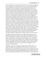
will all go out of step, and the result will be small. Figure 9.1 shows this in action.
If two signals are out of phase, but have the same frequency, then the sum of the product
can go to 0, even though there is a match. But using complex numbers (see Chapter 5), the
phase can be captured without ambiguity or mistake. It is this process that produces the
Fourier transform. For math’s sake, we can write it as
F f t e dt
i t
ω
ω
(
)
=
(
)
−
∫
where F is the Fourier-transformed representation of f, based on the angular frequency ω,
which is 2π times the frequency.
What does all this mean? It means that we have a mathematical way of converting a signal
to its frequencies. A continuous signal has a continuous (infinite) number of frequencies.
But, with the digital world, signals are always finite and discrete. We can shift from the
continuous Fourier transform and go to the discrete variant, however. This variant uses the
same math, but replaces the integral with a discrete sum. The result of a discrete Fourier
transform of a signal of a certain number of samples is a new signal with the same number
356 Chapter 9
www.newnespress.com
Intensity
Time
a) Original signal 2 cos(10 · 2 p x) + cos(30 · 2 p x), composed of two signals: one at a frequency of 30Hz, and another,
half as strong, at a frequency of 10Hz.
0
Intensity
Time
c) Overlap for 10Hz test signal in original signal, which does have a 10Hz component. Notice how the running
sum, representing the amount of overlap the test signal has with the original as a running sum of the product of
the two signals at each point, steadily increases. This 10Hz test signal is a match, and there will be a peak in
the Fourier transform at 10Hz.
0
Intensity
Frequency
b) Fourier Transform, or frequency plot, of the same signal. Noice how there are strong peaks at both 10Hz and
30Hz, with the 30Hz peak having twice the intensity. This is the advantage of the Fourier transform, which pulls
out the frequencies present in a signal.
0
0 10 20 30 40 50 60 70 80 90 100
Original signal
10Hz test function
Running sum (integral)
Intensity
Time
d) Overlap for 20Hz test signal in original signal, which does not have a 20Hz component. The running sum
now doesn’t steadily increase, from left to right, but instead vacillates around zero, as expected because the
test signal now does not overlap with the original signal. This 20Hz test signal is not a match, and there will
be no peak in the Fourier transform at 20Hz.
0
Original signal
10Hz test function
Running sum (integral)
Figure 9.1: Fourier Transform
The Future: Video Mobility and Beyond 357
www.newnespress.com
of samples, but with the first sample representing the lowest frequency—the larger the
sample, the more this frequency is present in the original signal—and so on.
The method now begins to become clear. Take the signal, then the discrete Fourier
transform of it. The most important frequencies will have the largest value, and less
important frequencies will have smaller values. Assigning more bits to the larger
frequencies and less bits to the smaller by quantization will compress the signal. Most of
the frequency components will actually get compressed to zero, or completely removed,
when compression is successful.
Coming back to video, the thought is the same. The discrete Fourier transform—and its
variant, the discrete cosine transform (DCT), which works with entirely real numbers (no
imaginary numbers)—can work in both the horizontal and vertical directions, to capture the
frequencies present in the image. Now, it may not seem that a video image obviously has
frequencies. Over the entire image, it probably doesn’t have any ones that can be seen
intuitively. But the trick is to divide the image up into small rectangles—the size depends
on a number of factors, such as how much or little the part of the image in the rectangle
varies—and do the frequency transform and subsequent quantization for each rectangle.
Now, the benefit for frequency information can begin to make sense. A rectangle whose
image barely changes, such as background shading, has very little frequency information,
and so can be compressed greatly. But even areas that represent real shapes can be
compressed rather well, with a lot of loss but preserving the rough character of that part of
the image. As long as each rectangle does not have a lot of irregularity in it, the
compression will be good for each rectangle. From here, the compressors try to figure out
how to make each rectangle as large as possible for the same bits, looking for areas with
lots of similarity.
This adaptive sizing of rectangles, and the rectangles themselves, can be seen fairly easy on
compressed images, but usually happens away from the action (intentionally, as we will
see). Let’s take the example in Figure 9.2.
The lefthand image is the original, and the righthand is with compression set high—as
would happen away from the action. Right away, you can see the outlines of the rectangles,
in this case, all of the same size, as this is a JPEG image. Most of the squares, such as those
for the sky and the solid parts of the building—wherever there is not a lot of detail—got
compressed down to no frequency components in any direction: a solid color. But some
areas had more than one frequency component that wasn’t compressed to zero. If you look
at the right side of the tower, where it meets the sky, you will notice that all of the squares
seem to have vertical bands, and thus are horizontally smooth. This happens because one
frequency component in the horizontal direction got retained, which makes sense for a
mostly vertical shape. Squares with more than one component in each direction can be seen
where people’s heads are.
358 Chapter 9
www.newnespress.com
9.1.2.2 Motion Compression
Once a still frame has been compressed, we can move on to compressing the motion itself.
The simple way of doing this would be to just have a sequence of compressed images, one
compressed image for each frame. This is actually done in a format called Motion JPEG.
However, doing so would not take advantage of the fact that most frames are nearly
identical, with similar backgrounds but different images of the active subjects as they move
around.
We can think of compressing the motion itself by starting out with the first frame, a
compressed still image like any other. But, for the following frame, imagine not storing
another compressed image. Instead, just store which pixels in the image, corresponding to a
moving subject, have moved, and in which direction they have moved. The decoder will
just copy those pixels forward, moving them according to the directions the encoder gives.
The only new pixels the encoder needs to send are those for the background that got
revealed as the moving subject moved away from them. As most objects are pretty solid or
large, the pixels in them move together, and so encoding regions of essentially uniform
motion is fairly simple and highly efficient. From this comes the dual concept of the key
frame (or I frame for intra-coded), the first frame in the sequence with the complete set of
pixels, and the intermediate frames (or P frame for predictive), the following frames that
only carry the motion and the newly revealed pixels.
This would work just fine, except that viewers like to jump around in videos, or
intermediate frames might get lost somewhere. If there were only one key frame, the video
would be ruined for any absence of even one bit of information of the intermediate frames.
To overcome that, the encoder starts off with a new key frame every so often. This effect,
too, is something you can see rather easily. DVDs and digital video recorders use similar
Figure 9.2: Compression Artifacts
The Future: Video Mobility and Beyond 359
www.newnespress.com
compression algorithms, with key frames spaced fairly far apart and a few dozen
intermediate frames in between. When you fast forward or rewind the video, you may see
these key frames go by, one by one, as still pictures. This is quite different than the old
analog VCR days, where the video would just animate faster, and happens because
processing the intermediate frames takes too much time for fast forwarding.
Figure 9.3 illustrates the parts of the intermediate frame that are used for added
compression.
Frame 1 Frame 2
a) The ball moves from Frame 1 to Frame 2.
b) The intermediate frame encoding for Frame 2 stores that
the pixels that make up the ball in Frame 1 need to move
down and to the right to make Frame 2.
c) The intermediate frame encoding for Frame 2 also stores
the newly revealed pixels for Frame 2, shown here.
Movement Revealed Background
Figure 9.3: Motion Compression
360 Chapter 9
www.newnespress.com
Video compression leaves much of the intelligence to the compressor: the decompressor is
required only to execute the instructions. More intelligent compressors can focus on the
subject matter of importance, and the decompressor itself does not need to understand what
matters more in the subject in order to do its job.
There are a few types of video codecs, all of them similar to each other, but with some
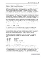
differences in the degree of intelligence and the type of formatting. ITU H.262, the codec
used in MPEG-2 video, is the most common codec, used in DVDs, as well as a wide
variety of downloadable Internet video content. The bitrate can go as high as 10Mbps for
standard-definition DVD video.
ITU H.264, for Advanced Video Coding (AVC) and the foundation for MPEG-4 video, was
designed to produce a far better picture at a significantly smaller bit rate—the goal is to be
about half the bit rate of MPEG-2, for the same quality. AVC includes a number of
improvements, including the ability for the decoders to smooth the edges between the
blocks, such as those seen in Figure 9.2. AVC is the foundation of most high-definition
(HD) video, including for Blu-ray video discs and many satellite and cable television
transmissions. AVC is also used in YouTube and other Adobe Flash–based video downloads.
Other, often proprietary, codecs exist for videoconferencing and webinar (web seminar)
broadcasts, which can take advantage of the constrained subject matter—a series of heads or
presentation slides, for example—to compress even better than general-purpose video
compressors.
9.1.3 Video Signaling and Bearer Technologies
Video must be carried in much the same way as voice. The video flow or call may need to
be set up—this is especially true for conferencing—and then the video stream itself must be
transported, along with the related audio streams.
9.1.3.1 Video Bearer
Let’s start with the video transport, as the bearer, first. Because many video downloads are
streaming, rather than conferencing, both real-time and stream-based transports can be
considered.
Real-time video transport is often based on the same RTP mechanism that is used for voice.
When transported this way, each of the frames in the video may span multiple RTP packets.
The opposite also will happen, and multiple frames may meet in any given RTP packet.
However, the RTP mechanism applies the same timestamp and sequence number functions
to the video stream, allowing the video decoder to piece back together the stream when
packets are lost or reordered. The video sender can send separate RTP streams, sharing the
same timestamp clock, for each of the media streams that make up the video. This can be