Managing and Mining Graph Data part 11 ppt
Bạn đang xem bản rút gọn của tài liệu. Xem và tải ngay bản đầy đủ của tài liệu tại đây (1.86 MB, 10 trang )
Graph Mining: Laws and Generators 81
Detailed description.
The first pattern we observe is the Weight Power
Law (WPL). Let 𝐸(𝑡), 𝑊 (𝑡) be the number of edges and total weight of a
graph, at time 𝑡. They, they follow a power law
𝑊 (𝑡) = 𝐸(𝑡)
𝑤
where 𝑤 is the weight exponent.
The weight exponent 𝑤 ranges from 1.01 to 1.5 for the real graphs studied
in [59], which included blog graphs, computer network graphs, and political
campaign donation graphs, suggesting that this pattern is universal to real so-
cial network-like graphs.
In other words, the more edges that are added to the graph, superlinearly
more weight is added to the graph. This is counterintuitive, as one would
expect the average weight-per-edge to remain constant or to increase linearly.
We find the same pattern for each node. If a node 𝑖 has out-degree 𝑜𝑢𝑡
𝑖
, its
out-weight 𝑜𝑢𝑡𝑤
𝑖
exhibits a “fortification effect”– there will be a power-law
relationship between its degree and weight. We call this the Snapshot Power
Law (SPL), and it applies to both in- and out- degrees.
Specifically, at a given point in time, we plot the scatterplot of the in/out
weight versus the in/out degree, for all the nodes in the graph, at a given time
snapshot. Here, every point represents a node and the 𝑥 and 𝑦 coordinates are
its degree and total weight, respectively. To achieve a good fit, we bucketize
the 𝑥 axis with logarithmic binning [64], and, for each bin, we compute the
median 𝑦.
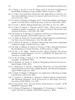
Examples in the real world. We find these patterns apply in several real
graphs, including network traffic, blogs, and even political campaign dona-
tions. A plot of WPL and SPL may be found in Figure 3.3.
Several other weighted power laws, such as the relationship between the
eigenvalues of the graph and the weights of the edges, may be found in [5].
Other metrics of measurement. We have discussed a number of patterns
found in graphs, many more can be found in the literature. While most of the
focus regarding node degrees has fallen on the in-degree and the out-degree
distributions, there are “higher-order” statistics that could also be considered.
We combine all these statistics under the term joint distributions, differentiat-
ing them from the degree-distributions which are the marginal distributions.
Some of these statistics include:
In and out degree correlation The in and out degrees might be indepen-
dent, or they could be (anti)correlated. Newman et al. [67] find a positive
correlation in email networks, that is, the email addresses of individuals
with large address books appear in the address books of many others.
82 MANAGING AND MINING GRAPH DATA
10
1
10
2
10
3
10
4
10
5
10
6
10
1
10
2
10
3
10
4
10
5
10
6
10
7
10
8
10
9
10
10
Committee−to−Candidate Scatter Plot
|E|
0.58034x + (0.61917) = y
0.7302x + (−0.35485) = y
1.5353x + (0.44337) = y
1.2934x + (−1.1863) = y
|W|
|dupE|
|dstN|
|srcN|
(a) WPL plot (b) inD-inW snapshot (c) outD-outW snapshot
Figure 3.3. Weight properties of the campaign donations graph: (a) shows all weight properties,
including the densification power law and WPL. (b) and (c) show the Snapshot Power Law for in-
and out-degrees. Both have slopes > 1 (“fortification effect”), that is, that the more campaigns an
organization supports, the superlinearly-more money it donates, and similarly, the more donations
a candidate gets, the more average amount-per-donation is received. Inset plots on (c) and (d)
show 𝑖𝑤 and 𝑜𝑤 versus time. Note they are very stable over time.
However, it is hard to measure this with good accuracy. Calculating this
well would require a lot of data, and it might be still be inaccurate for
high-degree nodes (which, due to power law degree distributions, are
quite rare).
Average neighbor degree We can measure the average degree 𝑑
𝑎𝑣
(𝑖)
of the neighbors of node 𝑖, and plot it against its degree 𝑘(𝑖). Pastor-
Satorras et al. [74] find that for the Internet AS level graph, this gives a
power law with exponent 0.5 (that is, 𝑑
𝑎𝑣
(𝑖) ∝ 𝑘(𝑖)
−0.5
).
Neighbor degree correlation We could calculate the joint degree distri-
butions of adjacent nodes; however this is again hard to measure accu-
rately.
2.4 Patterns in Evolving Graphs
The search for graph patterns has focused primarily on static patterns, which
can be extracted from one snapshot of the graph at some time instant. Many
graphs, however, evolve over time (such as the Internet and the WWW) and
only recently have researchers started looking for the patterns of graph evolu-
tion. Some key patterns have emerged:
Densification Power Law: Leskovec et al. [58] found that several real
graphs grow over time according to a power law: the number of nodes
𝑁(𝑡) at time 𝑡 is related to the number of edges 𝐸(𝑡) by the equation:
𝐸(𝑡) ∝ 𝑁 (𝑡)
𝛼
1 ≤ 𝛼 ≤ 2 (3.7)
where the parameter 𝛼 is called the Densification Power Law exponent,
and remains stable over time. They also find that this “law” exists for
Graph Mining: Laws and Generators 83
10
2
10
3
10
4
10
5
10
2
10
3
10
4
10
5
10
6
Number of edges
Number of nodes
Jan 1993
Apr 2003
Edges
= 0.0113 x
1.69
R
2
=1.0
10
5
10
6
10
7
10
5
10
6
10
7
10
8
Number of nodes
Number of edges
1975
1999
Edges
= 0.0002 x
1.66
R
2
=0.99
10
3.5
10
3.6
10
3.7
10
3.8
10
4.1
10
4.2
10
4.3
10
4.4
Number of edges
Number of nodes
Edges
= 0.87 x
1.18
R
2
=1.00
(a) arXiv (b) Patents (c) Autonomous Systems
Figure 3.4. The Densification Power Law The number of edges 𝐸(𝑡) is plotted against the number
of nodes 𝑁(𝑡) on log-log scales for (a) the arXiv citation graph, (b) the patents citation graph, and
(c) the Internet Autonomous Systems graph. All of these grow over time, and the growth follows a
power law in all three cases [58].
several different graphs, such as paper citations, patent citations, and the
Internet AS graph. This quantifies earlier empirical observations that the
average degree of a graph increases over time [14]. It also agrees with
theoretical results showing that only a law like Equation 3.7 can maintain
the power-law degree distribution of a graph as more nodes and edges
get added over time [37]. Figure 3.4 demonstrates the densification law
for several real-world networks.
Shrinking Diameters: Leskovec et al. [58] also find that the effective di-
ameters (definition 3.4) of graphs are actually shrinking over time, even
though the graphs themselves are growing. This can be observed after
the gelling point– before a certain point a graph is still building to nor-
mal properties. This is illustrated in Figure 3.5(a)– for the first few time
steps the diameter grows, but it quickly peaks and begins shrinking.
Component Size Laws As a graph evolves, a giant connected component
forms: that is, most nodes are reachable to each other through some
path. This phenomenon is present both in random and real graphs. What
is also found, however, is that once the largest component gels and edges
continue to be added, the sizes of the next-largest connected components
remain constant or oscillating. This phenomenon is shown in Figure 3.5,
and discussed in [59].
Patterns in Timings: There are also several interesting patterns regarding
the timestamps of edge additions. We find that edge weight additions to
a graph are bursty: over time, edges are not added to the overall graph
uniformly over time, but are uneven yet self-similar [59]. We illustrate
this in Figure 3.6. However, in the case of many graphs, timeliness of
a particular node is important in its edge additions. As shown in [56],
incoming edges to a blog post decay with a surprising power-law expo-
84 MANAGING AND MINING GRAPH DATA
0 10 20 30 40 50 60 70 80 90
0
2
4
6
8
10
12
14
16
18
20
time
diameter
t=31
0 10 20 30 40 50 60 70 80 90
10
0
10
1
10
2
10
3
10
4
10
5
10
6
time
CC size
CC1
CC2
CC3
t=31
0 0.5 1 1.5 2 2.5
x 10
5
0
100
200
300
400
500
600
|E|
CC size
CC2
CC3
(a) Diameter(t) (b) Largest 3 components (c) CC2 and CC3 sizes
Figure 3.5. Connected component properties of Postnet network, a network of blog posts. Notice
that we experience an early gelling point at (a), where the diameter peaks. Note in (b), a log-linear
plot of component size vs. time, that at this same point in time the giant connected component
takes off, while the sizes of the second and third-largest connected components (CC2 and CC3)
stabilize. We focus on these next-largest connected components in (c).
10
0
10
1
10
2
10
1
10
2
10
3
10
4
10
5
10
6
Number of in−links
Days after post
Posts
= 541905.74 x
−1.60
R
2
=1.00
(a) Entropy of edge additions (b) Decay of post popularity
Figure 3.6. Timing patterns for a network of blog posts. (a) shows the entropy plot of edge
additions, showing burstiness. The inset shows the addition of edges over time. (b) describes the
decay of post popularity. The horizontal axis indicates time since a post’s appearance (aggregated
over all posts), while the vertical axis shows the number of links acquired on that day.
nent of -1.5, rather than exponentially or linearly as one might expect.
This is shown in Figure 3.6.
These surprising patterns are probably just the tip of the iceberg, and there may
be many other patterns hidden in the dynamics of graph growth.
2.5 The Structure of Specific Graphs
While most graphs found naturally share many features (such as the small-
world phenomenon), there are some specifics associated with each. These
might reflect properties or constraints of the domain to which the graph be-
longs. We will discuss some well-known graphs and their specific features
below.
The Internet. The networking community has studied the structure of
the Internet for a long time. In general, it can be viewed as a collection of
interconnected routing domains; each domain is a group of nodes (such routers,
switches etc.) under a single technical administration [26]. These domains can
be considered as either a stub domain (which only carries traffic originating or
Graph Mining: Laws and Generators 85
Core
Layers
Hanging nodes
Figure 3.7. The Internet as a “Jellyfish” The Internet AS-level graph can be thought of as a core,
surrounded by concentric layers around the core. There are many one-degree nodes that hang
off the core and each of the layers.
terminating in one of its members) or a transit domain (which can carry any
traffic). Example stubs include campus networks, or small interconnections of
Local Area Networks (LANs). An example transit domain would be a set of
backbone nodes over a large area, such as a wide-area network (WAN).
The basic idea is that stubs connect nodes locally, while transit domains
interconnect the stubs, thus allowing the flow of traffic between nodes from
different stubs (usually distant nodes). This imposes a hierarchy in the In-
ternet structure, with transit domains at the top, each connecting several stub
domains, each of which connects several LANs.
Apart from hierarchy, another feature of the Internet topology is its apparent
Jellyfish structure at the AS level (Figure 3.7), found by Tauro et al. [79]. This
consists of:
A core, consisting of the highest-degree node and the clique it belongs
to; this usually has 8–13 nodes.
Layers around the core. These are organized as concentric circles around
the core; layers further from the core have lower importance.
Hanging nodes, representing one-degree nodes linked to nodes in the
core or the outer layers. The authors find such nodes to be a large per-
centage (about 40–45%) of the graph.
The World Wide Web (WWW). Broder et al. [24] find that the Web graph
is described well by a “bowtie” structure (Figure 3.8(a)). They find that the
Web can be broken in 4 approximately equal-sized pieces. The core of the
bowtie is the Strongly Connected Component (SCC) of the graph: each node
in the SCC has a directed path to any other node in the SCC. Then, there is
86 MANAGING AND MINING GRAPH DATA
the IN component: each node in the IN component has a directed path to all
the nodes in the SCC. Similarly, there is an OUT component, where each node
can be reached by directed paths from the SCC. Apart from these, there are
webpages which can reach some pages in OUT and can be reached from pages
in IN without going through the SCC; these are the TENDRILS. Occasionally,
a tendril can connect nodes in IN and OUT; the tendril is called a TUBE in this
case. The remainder of the webpages fall in disconnected components. A
similar study focused on only the Chilean part of the Web graph found that
the disconnected component is actually very large (nearly 50% of the graph
size) [11].
Dill et al. [33] extend this view of the Web by considering subgraphs of the
WWW at different scales (Figure 3.8(b)). These subgraphs are groups of web-
pages sharing some common trait, such as content or geographical location.
They have several remarkable findings:
1 Recursive bowtie structure: Each of these subgraphs forms a bowtie of
its own. Thus, the Web graph can be thought of as a hierarchy of bowties,
each representing a specific subgraph.
2 Ease of navigation: The SCC components of all these bowties are tightly
connected together via the SCC of the whole Web graph. This provides
a navigational backbone for the Web: starting from a webpage in one
bowtie, we can click to its SCC, then go via the SCC of the entire Web to
the destination bowtie.
3 Resilience: The union of a random collection of subgraphs of the Web
has a large SCC component, meaning that the SCCs of the individual
subgraphs have strong connections to other SCCs. Thus, the Web graph
is very resilient to node deletions and does not depend on the existence
of large taxonomies such as yahoo.com; there are several alternate paths
between nodes in the SCC.
We have discussed several patterns occurring in real graphs, and given some
examples. Next, we would like to know, how can we re-create these patterns?
What sort of mechanisms can help explain real-world behaviors? To answer
these questions we turn to graph generators.
3. Graph Generators
Graph generators allow us to create synthetic graphs, which can then be
used for, say, simulation studies. But when is such a generated graph “realis-
tic?” This happens when the synthetic graph matches all (or at least several) of
the patterns mentioned in the previous section. Graph generators can provide
insight into graph creation, by telling us which processes can (or cannot) lead
to the development of certain patterns.
Graph Mining: Laws and Generators 87
Disconnected
Components
IN OUT
Tube
SCC
TENDRILS
IN OUT
SCC
SCC
SCC
SCC
SCC
(a) The “Bowtie” structure (b) Recursive bowties
Figure 3.8. The “Bowtie” structure of the Web: Plot (a) shows the 4 parts: IN, OUT, SCC and
TENDRILS [24]. Plot (b) shows Recursive Bowties: subgraphs of the WWW can each be consid-
ered a bowtie. All these smaller bowties are connected by the navigational backbone of the main
SCC of the Web [33].
Graph models and generators can be broadly classified into five categories:
1 Random graph models: The graphs are generated by a random process.
The basic random graph model has attracted a lot of research interest
due to its phase transition properties.
2 Preferential attachment models: In these models, the “rich” get “richer”
as the network grows, leading to power law effects. Some of today’s
most popular models belong to this class.
3 Optimization-based models: Here, power laws are shown to evolve when
risks are minimized using limited resources. This may be particularly
relevant in the case of real-world networks that are constrained by geog-
raphy. Together with the preferential attachment models, optimization-
based models try to provide mechanisms that automatically lead to power
laws.
4 Tensor-based models: Because many patterns in real graphs are self-
similar, one can generate realistic graphs by using self-similar mecha-
nisms through tensor multiplication.
5 Internet-specific models As the Internet is one of the most important
graphs in computer science, special-purpose generators have been de-
veloped to model its special features. These are often hybrids, using
ideas from the other categories and melding them with Internet-specific
requirements.
We will discuss graph generators from each of these categories in this sec-
tion. This is not a complete list, but we believe it includes most of the key ideas
88 MANAGING AND MINING GRAPH DATA
Figure 3.9. The Erd
-
os-R
«
enyi model The black circles represent the nodes of the graph. Every
possible edge occurs with equal probability.
from the current literature. For each group of generators, we will try to provide
the specific problem they aim to solve, followed by a brief description of the
generator itself and its properties, and any open questions. We will also note
variants on each major generator and briefly address their properties. While we
will not discuss in detail all generators, we provide citations and a summary.
3.1 Random Graph Models
Random graphs are generated by picking nodes under some random prob-
ability distribution and then connecting them by edges. We first look at the
basic Erd
-
os-R
«
enyi model, which was the first to be studied thoroughly [40],
and then we discuss modern variants of the model.
The Erd
-
os-R
«
enyi Random Graph Model.
Problem being solved.
Graph theory owes much of its origins to the
pioneering work of Erd
-
os and R
«
enyi in the 1960s [40, 41]. Their random graph
model was the first and the simplest model for generating a graph.
Description and Properties. We start with 𝑁 nodes, and for every pair of
nodes, an edge is added between them with probability 𝑝 (as in Figure 3.9).
This defines a set of graphs 𝐺
𝑁,𝑝
, all of which have the same parameters
(𝑁, 𝑝).
Degree Distribution
The probability of a vertex having degree 𝑘 is
𝑝
𝑘
=
(
𝑁
𝑘
)
𝑝
𝑘
(1 − 𝑝)
𝑁−𝑘
≈
𝑧
𝑘
𝑒
−𝑧
𝑘!
with 𝑧 = 𝑝(𝑁 −1) (3.8)
Graph Mining: Laws and Generators 89
For this reason, this model is often called the “Poisson” model.
Size of the largest component
Many properties of this model can be solved ex-
actly in the limit of large 𝑁. A property is defined to hold for parameters (𝑁, 𝑝)
if the probability that the property holds on every graph in 𝐺
𝑁,𝑝
approaches 1
as 𝑁 → ∞. One of the most noted properties concerns the size of the largest
component (subgraph) of the graph. For a low value of 𝑝, the graphs in 𝐺
𝑁,𝑝
have low density with few edges and all the components are small, having an
exponential size distribution and finite mean size. However, with a high value
of 𝑝, the graphs have a giant component with 𝑂(𝑁) of the nodes in the graph
belonging to this component. The rest of the components again have an ex-
ponential size distribution with finite mean size. The changeover (called the
phase transition) between these two regimes occurs at 𝑝 =
1
𝑁
. A heuristic
argument for this is given below, and can be skipped by the reader.
Finding the phase transition point
Let the fraction of nodes not belonging to
the giant component be 𝑢. Thus, the probability of random node not belonging
to the giant component is also 𝑢. But the neighbors of this node also do not
belong to the giant component. If there are 𝑘 neighbors, then the probability
of this happening is 𝑢
𝑘
. Considering all degrees 𝑘, we get
𝑢 =
∞
∑
𝑘=0
𝑝
𝑘
𝑢
𝑘
= 𝑒
−𝑧
∞
∑
𝑘=0
(𝑢𝑧)
𝑘
𝑘!
(using Eq 3.8)
= 𝑒
−𝑧
𝑒
𝑢𝑧
= 𝑒
𝑧(𝑢−1)
(3.9)
Thus, the fraction of nodes in the giant component is
𝑆 = 1 − 𝑢 = 1 −𝑒
−𝑧𝑆
(3.10)
Equation 3.10 has no closed-form solutions, but we can see that when 𝑧 < 1,
the only solution is 𝑆 = 0 (because 𝑒
−𝑥
> 1 −𝑥 for 𝑥 ∈ (0, 1)). When 𝑧 > 1,
we can have a solution for 𝑆, and this is the size of the giant component. The
phase transition occurs at 𝑧 = 𝑝(𝑁 −1) = 1. Thus, a giant component appears
only when 𝑝 scales faster than 𝑁
−1
as 𝑁 increases.
1
𝑃 (𝑘) ∝ 𝑘
−2.255
/ ln 𝑘; [18] study a special case, but other values of the exponent 𝛾 may be possible with
similar models.
2
Inet-3.0 matches the Internet AS graph very well, but formal results on the degree-distribution are not
available.
3
𝛾 = 1 +
1
𝛼
as 𝑘 → ∞ (Eq. 3.16)
90 MANAGING AND MINING GRAPH DATA
Tree-shaped subgraphs Similar results hold for the appearance of trees of dif-
ferent sizes in the graph. The critical probability at which almost every graph
contains a subgraph of 𝑘 nodes and 𝑙 edges is achieved when 𝑝 scales as 𝑁
𝑧
where 𝑧 = −
𝑘
𝑙
[20]. Thus, for 𝑧 < −
3
2
, almost all graphs consist of isolated
nodes and edges; when 𝑧 passes through −
3
2
, trees of order 3 suddenly appear,
and so on.
Diameter
Random graphs have a diameter concentrated around log 𝑁/ log 𝑧,
where 𝑧 is the average degree of the nodes in the graph. Thus, the diameter
grows slowly as the number of nodes increases.
Clustering coefficient
The probability that any two neighbors of a node are
themselves connected is the connection probability 𝑝 =
<𝑘>
𝑁
, where < 𝑘 > is
the average node degree. Therefore, the clustering coefficient is:
𝐶𝐶
𝑟𝑎𝑛𝑑𝑜𝑚
= 𝑝 =
< 𝑘 >
𝑁
(3.11)
Open questions and discussion. It is hard to exaggerate the importance
of the Erd
-
os-R
«
enyi model in the development of modern graph theory. Even
a simple graph generation method has been shown to exhibit phase transitions
and criticality. Many mathematical techniques for the analysis of graph prop-
erties were first developed for the random graph model.
However, even though random graphs exhibit such interesting phenomena,
they do not match real-world graphs particularly well. Their degree distribu-
tion is Poisson (as shown by Equation 3.8), which has a very different shape
from power-laws or lognormals. There are no correlations between the de-
grees of adjacent nodes, nor does it show any form of “community” structure
(which often shows up in real graphs like the WWW). Also, according to Equa-
tion 3.11,
𝐶𝐶
𝑟𝑎𝑛𝑑𝑜𝑚
<𝑘>
=
1
𝑁
; but for many real-world graphs,
𝐶𝐶
<𝑘>
is independent
of 𝑁 (See figure 9 from [7]).
Thus, even though the Erd
-
os-R
«
enyi random graph model has proven to be
very useful in the early development of this field, it is not used in most of
the recent work on modeling real graphs. To address some of these issues, re-
searchers have extended the model to the so-called Generalized Random Graph
Models, where the degree distribution can be set by the user (typically, set to
be a power law).
Analytic techniques for studying random graphs involve generating func-
tions. A good reference is by Wilf [85].
Generalized Random Graph Models. Erd
-
os-R
«
enyi graphs result in a
Poisson degree distribution, which often conflicts with the degree distributions