Introduction to Modeling and Control of Internal Combustion Engine Systems P1 potx
Bạn đang xem bản rút gọn của tài liệu. Xem và tải ngay bản đầy đủ của tài liệu tại đây (2.56 MB, 30 trang )
Introduction to Modeling and Control of Internal
Combustion Engine Systems
Lino Guzzella and Christopher H. Onder
Introduction to Modeling
and Control of Internal
Combustion Engine
Systems
ABC
Prof. Dr. Lino Guzzella
ETH Zürich
Institute for Dynamic Systems & Control
Sonneggstr. 3
8092 Zürich
ETH-Zentrum
Switzerland
E-mail:
Dr. Christopher H. Onder
ETH Zürich
Institute for Dynamic Systems & Control
Sonneggstr. 3
8092 Zürich
ETH-Zentrum
Switzerland
E-mail:
ISBN 978-3-642-10774-0 e-ISBN 978-3-642-10775-7
DOI 10.1007/978-3-642-10775-7
Library of Congress Control Number: 2009940323
c
2010 Springer-Verlag Berlin Heidelberg
This work is subject to copyright. All rights are reserved, whether the whole or part of the mate-
rial is concerned, specifically the rights of translation, reprinting, reuse of illustrations, recitation,
broadcasting, reproduction on microfilm or in any other way, and storage in data banks. Dupli-
cation of this publication or parts thereof is permitted only under the provisions of the German
Copyright Law of September 9, 1965, in its current version, and permission for use must always
be obtained from Springer. Violations are liable to prosecution under the German Copyright Law.
The use of general descriptive names, registered names, trademarks, etc. in this publication does
not imply, even in the absence of a specific statement, that such names are exempt from the relevant
protective laws and regulations and therefore free for general use.
Typesetting: Data supplied by the authors
Production: Scientific Publishing Services Pvt. Ltd., Chennai, India
Cover Design: WMX Design, Heidelberg, Germany
Printed in acid-free paper
987654321
springer.com
Preface
Who should read this text?
This text is intended for students interested in the design of classical and novel
IC engine control systems. Its focus lies on the control-oriented mathematical
description of the physical processes involved and on the model-based control
system design and optimization.
This text has evolved from a lecture series held during the last several
years in the mechanical engineering (ME) department at ETH Zurich. The
target readers are graduate ME students with a thorough understanding of
basic thermodynamic and fluid dynamics proc e sses in internal combustion
engines (ICE). Other prerequisites are knowledge of general ME topics (cal-
culus, mechanics, etc.) and a first course in control systems. Students with
little preparation in basic ICE modeling and design are referred to [64], [97],
[194], and [206].
Why has this text been written?
Internal combustion engines represent one of the most important technological
success stor ie s in the last 100 years. These systems have beco me the most
frequently us e d sources of propulsion energy in passenger cars. One of the
main reasons that this has occurred is the very high energy density of liquid
hydrocarbon fuels. As long as fossil fuel resources are used to fuel cars, there
are no foreseeable alternatives that offer the same benefits in terms of cost,
safety, pollutant emission and fuel economy (always in a total cycle , or “well-
to-wheel” sense, see e.g., [5] and [68]).
Internal combustion engines still have a substantial po tential for improve-
ments; Diesel (compression ignition) engines can be made much cleaner and
Otto (spark ignition) engines still can be made much more fuel efficient. Each
goal c an be achieved only with the help of control systems. Moreover, with
the systems becoming increasingly complex, systematic and efficient system
VI Preface
design procedures have bec ome technological and commercial nece ssities. This
text addresses these issues by offering an introduction to model-based control
system design for ICE.
What can be learned from this text?
The primary emphasis is put on the ICE (torque production, pollutant for-
mation, etc.) and its auxiliary devices (air- charge control, mixture for mation,
pollutant abatement systems, etc.). Mathematical models for some of these
processes will be developed below. Using these models, selec ted feedforward
and feedback control problems will then be discussed.
A model-bas e d approach is chosen be c ause, even thoug h more cumbersome
in the beginning, it after proves to be the most cost-effective in the long run.
Especially the control system development and calibration processes benefit
greatly from mathematical models at early project stages.
The appendix contains a brie f summary of the most important controller
analysis and design methods, and a case study that analyzes a simplified idle-
sp e ed control problem. This includes some aspects of e xperimental parameter
identification and model validation.
What cannot be learned from this text?
This text treats ICE systems, i.e., the load torque ac ting on the engine is
assumed to be known and no drive-train or chassis problems will be discussed.
Moreover, this text does not attempt to describe all control loops present
in engine systems. The focus is on those problem areas in which the authors
have had the opportunity to work during earlier projects.
Acknowledgments
Many people have implicitly helped us to prepare this text. Sp e c ifically our
teachers, co lleagues and students have helped to bring us to the point where
we felt ready to write this text. Several people have helped us more explicitly
in preparing this manuscript: Alois Amstutz, with whom we work especially
in the area of Diesel engines, several of our doctoral students whose disser-
tations have been used as the nucleus of several sections (we re ference their
work at the appropria te places), Simon Frei, Marzio Locatelli and David Ger-
mann who worked on the idle-speed case study and helped streamlining the
manuscript, and, finally, Brigitte Rohrbach and Darla Peelle, who translated
our manuscripts from “Germlish” to English.
Zurich, Lino Guzzella
May 2004 Christopher H. Onder
Preface to the Second Edition
Why a second edition?
The discussions conce rning pollutant emissions and fuel economy of passenger
cars constantly intensified since the first edition of this book was published.
Concerns about the air quality, the limited resources of fossil fuels and the
detrimental effects of greenhouse gases further spurred the interest of both
the industry and ac ademia to work towards improved internal-combustion
engines for automotive applications. Not surprisingly, the first edition of this
monogra ph rapidly so ld out. When the publisher inquired about a second
edition, we decided to seize this opportunity for revising the text, correcting
several e rrors, and adding some new material. The following list outlines the
most important changes and additions included in this second edition:
• restructured and slightly extended section on superchargers, increasing the
comprehensibility;
• short subse c tion on rotationa l oscillations and their treatment on engine
test-be nches, being a safety-relevant aspect;
• improved physical and chemical model for the three-way catalyst, simplify-
ing the conception a nd realization of downstream air-to -fuel ratio control;
• complete section on modeling, detection, a nd control of engine knock;
• new methodology for the design of an air-to-fuel ratio controller exhibiting
several advantages over the traditional H
∞
approach;
• short introduction to thermody namic engine-cycle calculation and some
corresponding control-oriented asp e cts.
As in the first edition, the text is focused on those pr oblems we were (or
still are) working on in our group at ETH. Many exciting new ideas (HCCI
combustion, variable-compres sion engines , engines for high-octane fuels, etc.)
have been pro posed by other groups. However, simply reporting those concepts
without being able to round them off by first-hand expe rience would not add
any benefit to the existing literature. Therefore, they a re not included in
VIII Preface to t he Second Edition
this book, which should remain an introductory reference for students and
engineers new to the topic of internal-combustion engines.
Acknowledgements
We want to express our gratitude to the many colleagues and students who
reported to us errors and omissions in the first edition of this text.
Several people have helped us improving this monograph, in particular
Daniel Rupp, Roman M¨oller and Jonas Asprion who helped pre paring the
manuscript.
Zurich, Lino Guzzella
Septembe r 2009 Christopher H. Onder
Contents
1 Introduction . . . . . . . . . . . . . . . . . . . . . . . . . . . . . . . . . . . . . . . . . . . . . . . 1
1.1 Notation . . . . . . . . . . . . . . . . . . . . . . . . . . . . . . . . . . . . . . . . . . . . . . . 1
1.2 Control Systems for IC Engines . . . . . . . . . . . . . . . . . . . . . . . . . . . 4
1.2.1 Relevance of Engine Control Systems . . . . . . . . . . . . . . . . 4
1.2.2 Electronic Engine Control Hardware and Software . . . . . 5
1.3 Overview of SI Engine Control Problems . . . . . . . . . . . . . . . . . . . 6
1.3.1 General Remarks . . . . . . . . . . . . . . . . . . . . . . . . . . . . . . . . . . 6
1.3.2 Main Control Loops in SI Engines . . . . . . . . . . . . . . . . . . . 8
1.3.3 Future Developments . . . . . . . . . . . . . . . . . . . . . . . . . . . . . . 10
1.4 Overview of Control Problems in CI Engines . . . . . . . . . . . . . . . . 11
1.4.1 General Remarks . . . . . . . . . . . . . . . . . . . . . . . . . . . . . . . . . . 11
1.4.2 Main Control Loops in Diesel Engines . . . . . . . . . . . . . . . . 14
1.4.3 Future Developments . . . . . . . . . . . . . . . . . . . . . . . . . . . . . . 18
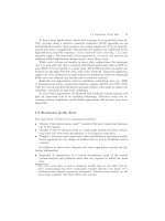
1.5 Structure of the Text . . . . . . . . . . . . . . . . . . . . . . . . . . . . . . . . . . . . 19
2 Mean-Value Models . . . . . . . . . . . . . . . . . . . . . . . . . . . . . . . . . . . . . . . 21
2.1 Introduction . . . . . . . . . . . . . . . . . . . . . . . . . . . . . . . . . . . . . . . . . . . . 22
2.2 Cause and Effect Diagrams . . . . . . . . . . . . . . . . . . . . . . . . . . . . . . . 24
2.2.1 Spark-Ignited Engines. . . . . . . . . . . . . . . . . . . . . . . . . . . . . . 25
2.2.2 Diesel Engines . . . . . . . . . . . . . . . . . . . . . . . . . . . . . . . . . . . . 28
2.3 Air System . . . . . . . . . . . . . . . . . . . . . . . . . . . . . . . . . . . . . . . . . . . . . 30
2.3.1 Receivers . . . . . . . . . . . . . . . . . . . . . . . . . . . . . . . . . . . . . . . . . 30
2.3.2 Valve Mass Flows . . . . . . . . . . . . . . . . . . . . . . . . . . . . . . . . . 31
2.3.3 Engine Mass Flows . . . . . . . . . . . . . . . . . . . . . . . . . . . . . . . . 35
2.3.4 Exhaust Gas Recirculation . . . . . . . . . . . . . . . . . . . . . . . . . 37
2.3.5 Supercharger . . . . . . . . . . . . . . . . . . . . . . . . . . . . . . . . . . . . . 40
2.4 Fuel System . . . . . . . . . . . . . . . . . . . . . . . . . . . . . . . . . . . . . . . . . . . . 52
2.4.1 Intro duction . . . . . . . . . . . . . . . . . . . . . . . . . . . . . . . . . . . . . . 52
2.4.2 Wall-Wetting Dynamics . . . . . . . . . . . . . . . . . . . . . . . . . . . . 53
2.4.3 Gas Mixing and Transport Delays . . . . . . . . . . . . . . . . . . . 63
2.5 Mechanical System . . . . . . . . . . . . . . . . . . . . . . . . . . . . . . . . . . . . . . 64
X Contents
2.5.1 Torque Generation . . . . . . . . . . . . . . . . . . . . . . . . . . . . . . . . 64
2.5.2 Engine Speed . . . . . . . . . . . . . . . . . . . . . . . . . . . . . . . . . . . . . 76
2.5.3 Rotational Vibration Dampers . . . . . . . . . . . . . . . . . . . . . . 8 1
2.6 Thermal Systems . . . . . . . . . . . . . . . . . . . . . . . . . . . . . . . . . . . . . . . . 85
2.6.1 Intro duction . . . . . . . . . . . . . . . . . . . . . . . . . . . . . . . . . . . . . . 85
2.6.2 Engine Exhaust Gas E nthalpy . . . . . . . . . . . . . . . . . . . . . . 86
2.6.3 Thermal Model of the Exhaust Manifold . . . . . . . . . . . . . 88
2.6.4 Simplified Thermal Model . . . . . . . . . . . . . . . . . . . . . . . . . . 89
2.6.5 Detailed Thermal Model . . . . . . . . . . . . . . . . . . . . . . . . . . . 90
2.7 Pollutant Formation . . . . . . . . . . . . . . . . . . . . . . . . . . . . . . . . . . . . . 98
2.7.1 Intro duction . . . . . . . . . . . . . . . . . . . . . . . . . . . . . . . . . . . . . . 98
2.7.2 Stoichiometric Combustion . . . . . . . . . . . . . . . . . . . . . . . . . 98
2.7.3 Non-Stoichiometric Combustion . . . . . . . . . . . . . . . . . . . . . 100
2.7.4 Pollutant Formation in SI Engines . . . . . . . . . . . . . . . . . . . 102
2.7.5 Pollutant Formation in Diesel Engines . . . . . . . . . . . . . . . 108
2.7.6 Control-Oriented NO Model . . . . . . . . . . . . . . . . . . . . . . . . 110
2.8 Pollutant Abatement Systems . . . . . . . . . . . . . . . . . . . . . . . . . . . . . 113
2.8.1 Intro duction . . . . . . . . . . . . . . . . . . . . . . . . . . . . . . . . . . . . . . 113
2.8.2 Three-Way Catalytic Converters, Basic Principles . . . . . 114
2.8.3 Modeling Three-Way Catalytic Converters . . . . . . . . . . . . 117
2.9 Pollution Abatement Systems for Diesel Engines. . . . . . . . . . . . . 137
3 Discrete-Event Models . . . . . . . . . . . . . . . . . . . . . . . . . . . . . . . . . . . . . 1 47
3.1 Introduction to DEM . . . . . . . . . . . . . . . . . . . . . . . . . . . . . . . . . . . . 148
3.1.1 When are DEM Req uired?. . . . . . . . . . . . . . . . . . . . . . . . . . 148
3.1.2 Discrete-Time Effects of the Combustion . . . . . . . . . . . . . 148
3.1.3 Discrete Action of the ECU . . . . . . . . . . . . . . . . . . . . . . . . . 150
3.1.4 DEM for Injection and Ignition . . . . . . . . . . . . . . . . . . . . . 153
3.2 The Most Important DEM in Engine Systems . . . . . . . . . . . . . . . 156
3.2.1 DEM of the Mean Torque Production . . . . . . . . . . . . . . . . 156
3.2.2 DEM of the Air Flow Dynamics . . . . . . . . . . . . . . . . . . . . . 161
3.2.3 DEM of the Fuel-Flow Dynamics . . . . . . . . . . . . . . . . . . . . 164
3.2.4 DEM of the Back-Flow Dynamics of CNG Engines . . . . 173
3.2.5 DEM of the Residual Gas Dynamics . . . . . . . . . . . . . . . . . 175
3.2.6 DEM of the Exhaust System . . . . . . . . . . . . . . . . . . . . . . . . 178
3.3 DEM Based on Cylinder Pressure Information . . . . . . . . . . . . . . 180
3.3.1 General Remarks . . . . . . . . . . . . . . . . . . . . . . . . . . . . . . . . . . 180
3.3.2 Estimation of Burned-Mass Fraction . . . . . . . . . . . . . . . . . 181
3.3.3 Cylinder Cha rge Estimation . . . . . . . . . . . . . . . . . . . . . . . . 183
3.3.4 Torque Variations Due to Pressure Pulsations . . . . . . . . . 188
Contents XI
4 Control of Engine Systems . . . . . . . . . . . . . . . . . . . . . . . . . . . . . . . . . 191
4.1 Introduction . . . . . . . . . . . . . . . . . . . . . . . . . . . . . . . . . . . . . . . . . . . . 192
4.1.1 General Remarks . . . . . . . . . . . . . . . . . . . . . . . . . . . . . . . . . . 192
4.1.2 Software Structure . . . . . . . . . . . . . . . . . . . . . . . . . . . . . . . . 193
4.1.3 Engine Op e rating Point . . . . . . . . . . . . . . . . . . . . . . . . . . . . 196
4.1.4 Engine C alibration . . . . . . . . . . . . . . . . . . . . . . . . . . . . . . . . 197
4.2 Engine Knock . . . . . . . . . . . . . . . . . . . . . . . . . . . . . . . . . . . . . . . . . . . 199
4.2.1 Autoignition Process . . . . . . . . . . . . . . . . . . . . . . . . . . . . . . . 200
4.2.2 Knock Criteria . . . . . . . . . . . . . . . . . . . . . . . . . . . . . . . . . . . . 202
4.2.3 Knock Detection . . . . . . . . . . . . . . . . . . . . . . . . . . . . . . . . . . 204
4.2.4 Knock Controller . . . . . . . . . . . . . . . . . . . . . . . . . . . . . . . . . . 208
4.3 Air/Fuel-Ratio Control . . . . . . . . . . . . . . . . . . . . . . . . . . . . . . . . . . . 210
4.3.1 Feedforward Control System . . . . . . . . . . . . . . . . . . . . . . . . 21 0
4.3.2 Feedback Control: Conventional Approach . . . . . . . . . . . . 215
4.3.3 Feedback Control: H
∞
. . . . . . . . . . . . . . . . . . . . . . . . . . . . . 217
4.3.4 Feedback Control: Internal-Model Control . . . . . . . . . . . . 229
4.3.5 Multivar iable Control of Air/Fuel Ratio and Engine
Speed . . . . . . . . . . . . . . . . . . . . . . . . . . . . . . . . . . . . . . . . . . . . 239
4.4 Control of an SCR System . . . . . . . . . . . . . . . . . . . . . . . . . . . . . . . . 244
4.5 Engine Thermomanagement . . . . . . . . . . . . . . . . . . . . . . . . . . . . . . 249
4.5.1 Intro duction . . . . . . . . . . . . . . . . . . . . . . . . . . . . . . . . . . . . . . 249
4.5.2 Control Problem Formulation . . . . . . . . . . . . . . . . . . . . . . . 250
4.5.3 Feedforward Control System . . . . . . . . . . . . . . . . . . . . . . . . 25 2
4.5.4 Experimental Results . . . . . . . . . . . . . . . . . . . . . . . . . . . . . . 255
A Basics of Modeling and Control-Systems Theory . . . . . . . . . . . 261
A.1 Modeling of Dynamic Systems . . . . . . . . . . . . . . . . . . . . . . . . . . . . 261
A.2 System Description and System Properties . . . . . . . . . . . . . . . . . . 270
A.3 Model Uncertainty . . . . . . . . . . . . . . . . . . . . . . . . . . . . . . . . . . . . . . . 276
A.4 Control-System Design for Nominal Plants . . . . . . . . . . . . . . . . . . 279
A.5 Control System Design for Uncertain Plants . . . . . . . . . . . . . . . . 288
A.6 Controller Discretization . . . . . . . . . . . . . . . . . . . . . . . . . . . . . . . . . 291
A.7 Controller Realization . . . . . . . . . . . . . . . . . . . . . . . . . . . . . . . . . . . . 301
A.7.1 Gain Scheduling . . . . . . . . . . . . . . . . . . . . . . . . . . . . . . . . . . . 301
A.7.2 Anti-Reset Windup . . . . . . . . . . . . . . . . . . . . . . . . . . . . . . . . 302
A.8 Further Reading . . . . . . . . . . . . . . . . . . . . . . . . . . . . . . . . . . . . . . . . . 303
B Case Study: Idl e Speed Control . . . . . . . . . . . . . . . . . . . . . . . . . . . . 305
B.1 Modeling of the Idle Speed System . . . . . . . . . . . . . . . . . . . . . . . . 306
B.1.1 Introduction . . . . . . . . . . . . . . . . . . . . . . . . . . . . . . . . . . . . . . 306
B.1.2 System Structure . . . . . . . . . . . . . . . . . . . . . . . . . . . . . . . . . . 307
B.1.3 Description of Subsystems . . . . . . . . . . . . . . . . . . . . . . . . . . 308
B.2 Parameter Identification and Model Validation . . . . . . . . . . . . . . 315
B.2.1 Static Behavior . . . . . . . . . . . . . . . . . . . . . . . . . . . . . . . . . . . 315
B.2.2 Dynamic Behavior . . . . . . . . . . . . . . . . . . . . . . . . . . . . . . . . . 319
XII Contents
B.2.3 Numerical Values of the Model Parameters . . . . . . . . . . . 321
B.3 Description of Linear System. . . . . . . . . . . . . . . . . . . . . . . . . . . . . . 324
B.4 Control System Design and Implementation. . . . . . . . . . . . . . . . . 326
C Combustion and Thermodynamic Cycle Calculation of
ICEs . . . . . . . . . . . . . . . . . . . . . . . . . . . . . . . . . . . . . . . . . . . . . . . . . . . . . . . 331
C.1 Fuels. . . . . . . . . . . . . . . . . . . . . . . . . . . . . . . . . . . . . . . . . . . . . . . . . . . 331
C.2 Thermodynamic Cycles . . . . . . . . . . . . . . . . . . . . . . . . . . . . . . . . . . 333
C.2.1 Real Engine-Cycle . . . . . . . . . . . . . . . . . . . . . . . . . . . . . . . . . 334
C.2.2 Approximations for the Heat Release . . . . . . . . . . . . . . . . 337
C.2.3 Csallner Functions . . . . . . . . . . . . . . . . . . . . . . . . . . . . . . . . . 338
References . . . . . . . . . . . . . . . . . . . . . . . . . . . . . . . . . . . . . . . . . . . . . . . . . . . . . 3 43
1
Introduction
In this chapter, first the notation used throughout this text is defined. It fur-
ther contains some general remarks on electronic engine control systems and
introduces the most common control problems encountered in spark ignition
(Otto or gasoline) and compression ignition (Diesel) engine systems. The in-
tention is to show the general motivation for using control systems and to
give the reader an idea of the problems that can be tackled by feedforward and
feedback control systems for both SI and CI engines.
The emphasis in this chapter is on qualitative arguments. The mathemati-
cally precise formulation is deferred to subsequent chapters. Those readers not
familiar with modern electronic sensors, actuators, and control hardware for
automotive applications may want to consult either [7], [108], or [125 ].
1.1 Notation
The notation used in this text is fairly standard. The derivative of a variable
x(t), with respect to its independent variable t, is denoted by
d
dt
x(t)
while the notation
˙x(t)
is used to indicate a flow of mass, energy, etc. Both variables
d
dt
x(t) and ˙x(t)
have the same units, but they are different objects. No spe c ial distinction is
made b e tween scalars, vectors and matrices. The dimensions of a variable, if
not a scalar, are explicitly defined in the context. Input signa ls are usually
denoted by u
and output signals by y
, whereas the index . . . specifies what
physical quantity is actuated or measured.
Concentrations of chemical species C are denoted by [C], with units
mol/mol, with respect to the reference substance. The concentrations are
2 1 Introduction
therefore limited to the interval [0, 1]. The concentration of pollutant species
are often shown in plots or tables using ppm units (part per million), i.e., by
using a amplification factor of 10
6
. For mass storage and tr ansportation mod-
els it is advantageous to use mass fr actions, which are denoted by ξ having
units [kg/kg].
In general, all var iables are defined at that place in the text where they
are used for the first time. To facilitate the reading, some symbols have been
reserved for special physical quantities:
α [
W
m
2
K
] heat-transfer coe fficient
A [m
2
] area
c
x
[
J
kgK
, -] sp e cific heat capacities (x = p, v), concentration of x
ε [-] compression ratio, volume fraction
η [-] efficiency
φ [
◦
, rad] crank angle
γ [-] gear ratio
H [J] enthalpy
κ [-] r atio of s pecific heats
λ [-] air-to-fuel ratio, volumetric efficiency, Lagrange multiplier
m [kg] mass
M [
kg
mol
] molar mass
N [-] number of engine revolutions per cycle
(1 for two-stroke, 2 for four-stroke engines)
ν [-] stoichiometric coefficient
p [P a, bar] pressure
P [W ] power
Π [-] pressure ratio
Q [J] heat
r [m,
mol
s
] radius, reaction rate
ρ [
kg
m
3
] density
R [
J
kgK
] sp e cific gas constant
R [
J
molK
] universal gas constant
σ
0
[-] stoichiometric air-to-fuel ratio
t [s] time (independent variable)
τ [s] time (interval or constant)
ϑ [K,
◦
C] temperature
θ [-] occupancy
T [Nm] torque
Θ [m
2
kg] rotational inertia
u, y [-] control input, system output (both normalized)
V [m
3
, l] volume
ζ [
◦
] ignition angle
ω [
rad
s
] rotational speed or angular frequency
ξ [-] mass fraction
1.1 Notation 3
Similarly, some indices have been reserved for special use. The following list
shows what each of them stands for:
α, a, β ambient air
c compressor or cylinder
e engine
eg exhaust gas
egr, ε exhaust-gas recirculation
f, ϕ, ψ fuel
γ engine outlet
l load
m manifold or mean value
seg segment
t turbine
ξ combustion
ζ timing (e.g. of ignition or injection)
In a turbocharged engine system, the four most important locations are des-
ignated by the indices 1 for “before compressor,” 2 for “after compressor,” 3
for “after engine,” and 4 for “after turbine.”
In general, all numerical values listed in this text are shown in SI units. A
few exc e ptions are made where non-SI units are widely accepted. These few
cases are explicitly mentioned in the text.
The most commonly used acronyms are:
BDC (TDC) bo ttom (top) dead ce nter (piston at lowest (topmo st)
position)
BMEP or p
me
(brake) mean-effective pressure
bsfc brake specific fuel-consumption
CA crank angle
CI compression ignition (in Diesel engines)
CNG compressed natural gas
COM control-oriented model
DEM discrete-event model
DPF Diesel particulate-filter
ECU electronic (or engine) control unit
IEG induction-to-exhaust delay
IPS induction-to-powerstroke delay
IVC (IVO) inlet-valve closing (opening)
EVC (EVO) exhaust-valve closing (opening)
MBT maximum brake torque (ignition or injection timing)
OC oxidation catalyst
ODE ordinary differential eq uation
ON octane number
PDE partial differential equation
PM particulate matter
4 1 Introduction
SCR selective catalytic reduction
SI spark ignition (in Otto/gasoline/gas engines)
TPU time-processing unit
TWC three-way catalytic converter
VNT variable-nozzle turbine
WOT wide-open throttle
1.2 Control Systems for IC Engines
1.2.1 Relevance of Engine Control Systems
Future cars are expected to incorporate approximately one third of their parts
value in electric and electronic components. These devices help to reduce the
fuel consumption and the emission of pollutant species, to incr e ase s afety,
and to impr ove the drivability and comfort of passenger cars. As the elec-
tronic control sys tems become more complex and powerful, an ever increasing
number of mechanical functions are being replaced by electric and electronic
devices. An example of such an advanced vehicle is shown in Fig. 1.1.
Fig. 1.1. Wiring harness of a modern vehicle (Maybach), reprinted with the per-
mission of Daimler AG.
In such a system, the engine is only one part within a larger structure.
Its main input and output signals are the commands issued by the electronic
1.2 Control Systems for IC Engines 5
control unit (ECU) or directly by the driver, and the load torque transmitted
through the clutch onto the engine’s flywheel. Figure 1.2 shows a possible
substructure of the vehicle control system. In this text, only the “ICE” (i.e.,
the engine and the corresponding hardware and software needed to control
the engine) will be discussed.
Control systems were introduced in ICE on a larger scale with the advent of
three-way catalytic converters for the pollutant reduction of SI engines. Good
exp eriences with these systems and substantial prog ress in microelectronic
components (performance and cost) have opened up a path for the application
of electronic control systems in many other ICE problem area s. It is clear
that the realization of the future, more complex, engine systems, e.g ., hybrid
power trains or homogeneous charge compression ignition engines, will not be
possible without sophisticated control s ystems.
Fig. 1.2. Substructure of a complete vehicle control system.
1.2.2 Electronic Engine Control Hardware and Software
Typically, an electronic engine control unit (ECU) includes standar d micro-
controller hardware (process interfaces, RAM/ROM, CPU, etc.) and at least
one additional piece of hardware, which is often designated as a time pro-
cessing u nit (TPU), see Fig. 1.3. This TPU synchronizes the engine control
commands with the reciprocating action of the engine. The synchronization of
6 1 Introduction
the ECU with the e ngine is analyzed in more detail in Sec. 3.1.3.
1
Notice also
that clock rates of ECU microprocessors are typically much lower than those
of desktop c omputers due to electromagnetic compatibility c onsiderations.
ECU software has typically been written in assembler code, with propri-
etary real-time kernels. In the last few years there has been a stro ng ten-
dency towards standardized high-level programming interfaces. Interestingly,
the software is structured to r e flec t the primary physical connections of the
plant to be controlled [70].
input
signals
from
engine
command
signals to
engine
crank−angle pulses
microcontroller
amplifier, relays, etc.
AD converter, digital input
DA converter, digital output
event
controller
(TPU)
Fig. 1.3. Internal structure of an electronic engine control unit.
1.3 Overview of SI Engine Control Problems
1.3.1 General Remarks
The majority of modern passenger cars are still equippe d with po rt (indi-
rect) injection spark-ignited gasoline engines. The premixed and stoichiomet-
ric combustion of the Otto process per mits an extremely efficient exhaust gas
purification with three-way catalytic converters and produces very little par-
ticulate matter (PM). A standard configuration of such an engine is shown in
Fig. 1.4.
The to rque of a stoichiometric SI engine is co ntrolled by the quantity
of air/fuel mixture in the cylinder during each stroke (the quality, i.e., the
air/fuel ratio, remains constant). Typically, this quantity is varied by chang-
ing the intake pressure and, hence, the density of the air/fuel mixture. Thus,
a throttle plate is used upstream of the combustion process in the intake
system. This solution is relatively simple and reliable, but it produces sub-
stantial “pumping losses” that negatively affect the part-load efficiency of the
1
The reciprocating or event-based behavior of all ICE also has important conse-
quences for the controller design process. These problems will be addressed in
Chapters 3 and 4.
1.3 Overview of SI Engine Control Problems 7
engine. Novel approaches, such as electronic throttle control, variable valve
timing, etc., which offer improved fuel economy and pollutant emission, will
be discussed below.
FP
TA
MA
ET
PM
TE
SE
TWC
λ λ
AK
CP
Tank
SA
IC
AK
CP
IC
MA
SE
FP
PM
ET
TA
TE
CC
manifold pressure sensor
electronic throttle
intake air temperature sensor
cooling water temperature sensor
active carbon canister
air/fuel ratio sensors
knock sensor
camshaft sensor
ignition command
air mass-flow sensor
engine speed sensor
fuel pressure control
CC
VE
VE
SA
TWC
ECU
CCV
DP
EGR valve
secondary air valve
3-way catalyst
controller
CC control valves
driver pedal
λ
1,2
1
2
ECU
CCV
CCV
DP
TWC
Fig. 1.4. Overview over a typical SI engine system structure.
A simplified control-oriented substructure of an SI eng ine is shown in
Fig. 1.5. The main blocks are the fuel path P
ϕ
and the air path P
α
, which
define the mixture entering the cylinder, and the combustion block P
χ
that
determines the amount of torque produced by the engine.
Other engine outputs are the knock signal y
ζ
(as measured by a knock
sensor P
ζ
) and the engine-out air/fuel ratio y
λ
(as measured by a λ sensor P
λ
mounted as close as possible to the exhaust valves). The engine speed ω
e
is
the output of the block P
Θ
, taking into account the rotational inertia of the
engine, whose inputs are the e ngine torque T
e
and the load torque T
l
.
The four most important control loops are indicated in Fig. 1.5 as well:
• the fuel-injection feedforward loop;
• the air/fuel ratio feedback loop;
• the ignition angle feedforward
2
loop; and
• the knock feedback loop.
In addition, the following feedforward or feedback loops are present in
many engine systems:
3
2
Closed-loop control has been proposed in [60] using the spark plug as an ion
current sensor.
3
Modern SI engines can include several other control loops.
8 1 Introduction
• idle and cruis e speed control;
• exhaust gas recirculation (for reducing emission during cold-start or for
lean-burn engines);
• secondary air injection (for faster catalyst light-off); and
• canister purge management (to avoid hydro c arbon evaporation).
Fig. 1.5. Basic SI engine control substructure.
1.3.2 Main Control Loops in SI Engines
Air/Fuel Ratio Control
The air/fuel ratio control problem has been instrumental in paving the road
for the introduction of several sophisticated automotive control systems. For
this reason, it is described in some detail.
The pollutant emissions of SI eng ines (mainly hydrocarbon (HC), carbon
monoxide (CO), and nitrogen oxide (NO
x
)) grea tly exceed the limits imposed
by most regulatory boards, and future emission legislation will require sub-
stantial additional reductions of pollutant emission levels. These requirements
can only be satisfied if appropriate e xhaust gas a fter-treatment systems are
used.
The key to clean SI engines is a three-way catalytic converter (TWC)
system whose stationary conversion efficiency is depicted in Fig. 1.6. Only for
a very narrow air/fuel ratio “window,” whose mean value is slightly below
the stoichiometric level, can all three pollutant species pr e sent in the exhaust
1.3 Overview of SI Engine Control Problems 9
Fig. 1.6. Conversion efficiency of a TWC (after light-off, stationary behavior).
gas be almost completely converted to the innocuous compo nents water and
carbon dioxide. In particular, when the engine runs under lean conditions,
the reduction of nitrogen oxide stops almost completely, because the now
abundant free oxygen in the e xhaust gas is used to oxidize the unburned
hydrocarbon and the carbon monoxide. Only when the engine runs under
rich conditions do the unburned hydrocarbon (HC) and the carbon monoxide
(CO) act as agents reducing the nitrogen oxide on the catalys t, thereby causing
the desired TWC behavior.
The mean air/fuel ratio can be kept within this narrow band only if elec-
tronic control systems and appropriate sensors and actuators are used. The
air/fuel ratio sensor (λ sensor) is a very important component in this loo p. A
precise fuel injection sy stem also is necessary. This is currently realized using
“sequential multiport injectors.” Each intake p ort has its own injector, which
injects fuel sequentially, i.e., only when the corresponding intake valves are
closed.
Finally, appropriate control algorithms have to be implemented in the
ECU. The fuel-injection feedforward controller F
ϕ
tries to quickly realize a
suitable injection timing based only on the measured air-pa th input informa-
tion (either intake air mass flow, intake manifold pressure, o r throttle plate
angle and engine speed). The air/fuel r atio feedback control system C
λ
com-
pens ates the unavoidable err ors in the feedforward loop. While it guarantees
the mean value of the air/fuel ratio to be at the stoichiometric level, it cannot
prevent tra nsient excursions in the air/fuel ratio.
Ignition Control
Another important example of a control system in SI engines is the spark angle
control system. This example shows how control systems ca n help improve fuel
economy as well.
10 1 Introdu ction
In fact, the efficiency of SI engines is limited, a mong other factors, by
the knock phenomenon. Knock (although still not fully understood) results
from an unwanted self-ignition process that leads to loc ally very high pressure
peaks that can destroy the rim of the piston and other parts in the cylinder.
In order to prevent knocking, the compression ratio must be kept below a safe
value and ignition timing must be optimized off-line and on-line.
A first optimization takes place during the calibration phase (experiments
on engine o r chassis dynamometers) of the engine development process. The
nominal spark timing data obtained are stored in the ECU. An on-line spark
timing control system is required to handle changing fuel qualities and engine
characteristics. The key to this component is a knock sensor and the corre-
sp onding signal proc e ssing unit that monitors the combustion process and
signals the onset of knocking.
The feedforward controller F
ζ
, introduced in Fig. 1.5, computes the nomi-
nal ignition angles (realizing ma ximum brake torque while avoiding knock and
excessive engine-out pollution levels) depending on the engine speed and load
(as measured by manifold pressure or other related signals). This correlation
is sta tic and is only o ptimal for that e ngine fro m which the ignition data was
obtained during the calibration of the ECU. The feedback control system C
ζ
utilizes the output of the knock detection system to adapt the ignition angle to
a safe and fuel efficient va lue des pite variations in environmental conditions,
fuel quality, etc.
1.3.3 Future Developments
Pollutant emission levels of stoichiometric SI engines are or soon will be a
“problem solved” such that the focus of research and development effor ts can
be redirected towards the improvement of the fuel economy. The most severe
drawbacks of current SI engines are evident in par t-load operating conditions.
As Fig . 1 .7 shows, the averag e efficiency even of mo dern SI engines remains
substantially be low their best bsfc
4
values. This is a problem because most
passenger cars on the average (and also on the governmental test cycles) utilize
less tha n 10% of the ma ximum engine power.
5
Not surprisingly, cy cle-averaged
“tank-to-wheel” efficiency data of actual passenger cars are between 12% and
18% only. The next step in the development of SI engines therefore will be a
substantial improvement of their part-load efficiency.
Several ideas have been proposed to improve the fuel efficiency of SI en-
gines, all of which include some control actions, e.g.,
• variable valve timing systems (electromagnetic or electrohydraulic);
• downsizing and supercharging systems;
• homogeneous and stratified le an combustion SI engines;
4
Brake-specific fuel consumption (u su ally in g fuel/kWh mechanical work).
5
Maximum engine power is mainly determined by the customer’s expectation of
acceleration performance and is, therefore, very much depend ent on vehicle mass.
1.4 Overview of Control Problems in CI Engines 11
4 6 8 10 12 14 16
2
4
6
8
10
0.1
0.2
η=0.25
0.3
0.33
0.35
0.36
c
m
p [bar]
[m/s]
me
Fig. 1.7. Engine map (mean effective pressure versus mean piston speed) of a
modern SI engine, gray area: part- load zone, η =const: iso-efficiency curves. For the
definition of p
me
and c
m
see Sect. 2.5.1.
• variable compression ratio engines; and
• engines with improved thermal management.
These systems reduce the pumping work required in the gas exchange part
of the Otto cycle, reduce mechanical friction, or improve the thermodynamic
efficiency in part-load conditions.
Another approach to improving part-load efficiency is to include novel
power train components, such as starter-generator
6
devices, CVTs
7
, etc. As
mentioned in the Introduction, these approaches will not be analyzed in this
text. Interested readers are referred to the textbook [81].
1.4 Overview of Control Problems in CI Engines
1.4.1 General Remarks
Diesel engines are inherently more fuel-efficient than ga soline engines (see
Appendix C), but they cannot use the pollutant abatement systems that have
proved to be so successful in gasoline engines. In fact, the torque output of
Diesel engines is controlled by changing the air/fuel ratio in the combustion
6
These advanced electric motors and generators typically have around 5 kW me-
chanical power and permit several improvements like idle-load shut-off strategies
or even “mild hybrid” concepts.
7
Continuously variable transmissions allow for the operation of the engine at the
lowest possible speed and highest possible load, thus partially avoiding the low
efficiency points in the engine map.
12 1 Introdu ction
chamber. This approach is not compatible with the TWC working principle
introduced above.
In naturally aspirated Diesel engines, the amount of air available is appro-
ximately the same for all loads, and only the amount of fuel injected changes
in accordance with the driver’s torque request. In mo dern CI engines the s itua -
tion is more complex since almost all engines are turbocharged. Turbochargers
introduce additional feedba ck paths, consider ably complicating the dynamic
behavior of the entire engine system. Additionally, pre-chamber injection has
been replaced by direct-injection systems. The injection is thereby realized
using either integrated-pump injectors or so-called common-rail systems, of
which particularly the latter introduces several additional degre e s of freedom.
p
2
u
vnt
uu
i
u
cr
CR
IC
CAT
VNT
COM
T
l
ω
e
ω
tc
ϑ
1
tank
p
c
IR
OR
ECU
p
cr
m
.
ϑ
cw
CAT
COM
CR
IR
OR
IC
VNT
WG
oxidation catalytic converter
compressor
common-rail system
intake receiver
outlet receiver
intercooler
variable nozzle turbine
waste-gate (alternative to VNT)
u
u
u
u
u
T
m
EGR valve(s) command
CR pump command
injection command
turbine nozzle command
WG command
load torque at the flywheel
turbocharger speed
total engine-in mass flow
vnt
i
cr
p
p
p
m
m
pressure after COM
intake pressure
CR injection pressure
intake air mass flow
intake air temperature
cooling water temperature
engine speed
exhaust gas recirculation
2
1
c
cr
cw
e
ϑ
ω
ϑ
l
tc
ω
c
.
WG
u
WG
WG
c
ε1,2
ε1,2
m
.
e
e
.
egr
.
m
.
egr
Fig. 1.8. Overview of a typical system structure of a Diesel engine.
Compression ignition, or Diesel engines, have been traditionally less ad-
vanced in electronic controller utilization due to cost, reliability, and image
problems in the past. However this situation has changed, and today, elec-
tronic control systems help to substantially improve the total system behavior
(espec ially the pollutant emission) of Diesel engines [79].
Figure 1.8 shows an overview of a typical modern Diesel engine as used in
passenger cars. The main objective for electronic Diesel-engine control-systems
is to provide the required engine torque while minimizing fuel consumption
and complying with exhaust-gas emissio ns and noise level regulations. This
requires an optimal coordina tion of injection, turbocharger and exhaust- gas
recirculation (EGR) systems in stationary and transient operating conditions.
1.4 Overview of Control Problems in CI Engines 13
From a control-engineering point of view, there are three important paths
which have to be considered: fuel, air and EGR. Figure 1.9 shows a schematic
overview of the basic structure of a typical Diesel-engine control-system,
clearly pointing out these three paths (for more details on the inner structure
of the Diesel engine, see Sect. 2.1). Notice that a speed controller is standard
in Diesel engines: The top speed must be limited in order to prevent engine
damage whereas the lower limit is imposed by the desired running smoothness
when idling.
The fuel path with the outputs torque, speed, and exhaust-gas emissions
obtains its inputs fro m the injection controller. The control inputs to the fuel
path are start of injection, injection duration, and injection pressure. With
common-rail systems, new degrees of freedom, such as the choice of a pilot
injection, main and after-injection quantities with different dwell times in-
between, are added. The injected fuel mass is, if necessary, adjusted by the
sp e ed controller and has an upper boundary o ften called the smoke limit:
Using the measurement of the air mass-flow into the engine, the maximum
quantity of injected fuel is calculated such that the a ir/fuel ratio doe s not fall
below a certain (constant or operating-point dependent) value. This prevents
the engine from producing visible smo ke as often seen on older vehicles during
heavy accele ration.
Fig. 1.9. Basic Diesel-engine control-system structure, variables as defined in
Fig. 1.8.
The turbocharger dominates the air path. Especially in applications with
heavy transient operations, turbocharger designs with small A/R ratios (noz-