CCNA Security 1.0 pot
Bạn đang xem bản rút gọn của tài liệu. Xem và tải ngay bản đầy đủ của tài liệu tại đây (5.7 MB, 283 trang )
CCNA Security 1.0
Student Lab Manual
This document is exclusive property of Cisco Systems, Inc. Permission is granted
to print and copy this document for non-commercial distribution and exclusive
use by instructors in the CCNA Security course as part of an official Cisco
Networking Academy Program.
All contents are Copyright © 1992–2009 Cisco Systems, Inc. All rights reserved. This document is Cisco Public Information. Page 1 of 4
CCNA Security
Chapter 1 Lab A: Researching Network Attacks and Security Audit
Tools
Objectives
Part 1: Researching Network Attacks
• Research network attacks that have occurred.
• Select a network attack and develop a report for presentation to the class.
Part 2: Researching Security Audit Tools
• Research network security audit tools.
• Select a tool and develop a report for presentation to the class.
Background/Scenario
Network attacks have resulted in the loss of sensitive data and significant network downtime. When a network
or the resources in it are inaccessible, worker productivity can suffer, and business income may be lost.
Attackers have developed many tools over the years to attack and compromise the networks of organizations.
These attacks take many forms, but in most cases, they seek to obtain sensitive information, destroy
resources, or deny legitimate users access to resources.
To understand how to defend a network against attacks, an administrator must first identify network
vulnerabilities. Specialized security audit software developed by equipment and software manufacturers can
be used to help identify potential weaknesses. In addition, the same tools used by attackers can be used to
test the ability of a network to mitigate an attack. After the vulnerabilities are known, steps can be taken to
help mitigate the network attacks.
This lab provides a structured research project that is divided into two parts: Researching Network Attacks
and Researching Security Audit Tools. You can elect to perform Part 1, Part 2, or both. Let your instructor
know what you plan to do so to ensure that a variety of network attacks and vulnerability tools are reported on
by the members of the class.
In Part 1, you research various network attacks that have actually occurred. You select one of these and
describe how the attack was perpetrated and how extensive the network outage or damage was. You also
investigate how the attack could have been mitigated or what mitigation techniques might have been
implemented to prevent future attacks. You prepare a report based on a predefined form included in the lab.
In Part 2, you research network security audit tools and investigate one that can be used to identify host or
network device vulnerabilities. You create a one-page summary of the tool based on a predefined form
included in the lab. You prepare a short (5–10 minute) presentation to present to the class.
You may work in teams of two with one person reporting on the network attack and the other reporting on the
security audit tools. Each team member delivers a short overview (5–10 minutes) of their findings. You can
use live demonstrations or PowerPoint to summarize your findings.
CCNA Security
All contents are Copyright © 1992–2009 Cisco Systems, Inc. All rights reserved. This document is Cisco Public Information. Page 2 of 4
Required Resources
• Computer with Internet access for research.
• Presentation computer with PowerPoint or other presentation software installed.
• Video projector and screen for demonstrations and presentations.
Part 1. Researching Network Attacks
In Part 1 of this lab, you research various network attacks that have actually occurred and select one on
which to report. Fill in the form below based on your findings.
Step 1: Research various network attacks.
List some of the attacks you identified in your search.
_______________________________________________________________________________________
_______________________________________________________________________________________
_______________________________________________________________________________________
Step 2: Fill in the following form for the network attack selected.
Name of attack:
Type of attack:
Dates of attacks:
Computers / Organizations affected:
How it works and what it did:
CCNA Security
All contents are Copyright © 1992–2009 Cisco Systems, Inc. All rights reserved. This document is Cisco Public Information. Page 3 of 4
Mitigation options:
References and info links:
Presentation support graphics (include PowerPoint filename or web links):
Part 2. Researching Security Audit Tools
In Part 2 of this lab, you research network security audit tools and attacker tools and investigate one that can
be used to identify host or network device vulnerabilities. Fill in the report below based on your findings.
Step 1: Research various security audit and network attack tools.
List some of the tools that you identified in your search.
_______________________________________________________________________________________
_______________________________________________________________________________________
_______________________________________________________________________________________
Step 2: Fill in the following form for the security audit or network attack tool selected.
Name of tool:
Developer:
Type of tool (character-based or GUI):
Used on (network device or computer host):
Cost:
Description of key features and capabilities of product or tool:
CCNA Security
All contents are Copyright © 1992–2009 Cisco Systems, Inc. All rights reserved. This document is Cisco Public Information. Page 4 of 4
References and info links:
Presentation support graphics:
Step 3: Reflection
a. What is the prevalence of network attacks and what is their impact on an organization’s operation?
What are some key steps organizations can take to help protect their networks and resources?
________________________________________________________________________________
________________________________________________________________________________
________________________________________________________________________________
________________________________________________________________________________
________________________________________________________________________________
b. Have you actually worked for an organization or know of one where the network was compromised? If
so, what was the impact to the organization and what did they do about it?
________________________________________________________________________________
________________________________________________________________________________
________________________________________________________________________________
c. What steps can you take to protect your own PC or laptop computer?
________________________________________________________________________________
________________________________________________________________________________
________________________________________________________________________________
All contents are Copyright © 1992–2009 Cisco Systems, Inc. All rights reserved. This document is Cisco Public Information. Page 1 of 42
CCNA Security
Chapter 2 Lab A: Securing the Router for Administrative Access
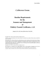
Topology
IP Addressing Table
Device
Interface IP Address Subnet Mask Default Gateway
Switch Port
R1 FA0/1 192.168.1.1 255.255.255.0 N/A S1 FA0/5
S0/0/0 (DCE) 10.1.1.1 255.255.255.252 N/A N/A
R2 S0/0/0 10.1.1.2 255.255.255.252 N/A N/A
S0/0/1 (DCE) 10.2.2.2 255.255.255.252 N/A N/A
R3 FA0/1 192.168.3.1 255.255.255.0 N/A S3 FA0/5
S0/0/1 10.2.2.1 255.255.255.252 N/A N/A
PC-A NIC 192.168.1.3 255.255.255.0 192.168.1.1 S1 FA0/6
PC-C NIC 192.168.3.3 255.255.255.0 192.168.3.1 S3 FA0/18
CCNA Security
All contents are Copyright © 1992–2009 Cisco Systems, Inc. All rights reserved. This document is Cisco Public Information. Page 2 of 42
Objectives
Part 1: Basic Network Device Configuration
• Cable the network as shown in the topology.
• Configure basic IP addressing for routers and PCs.
• Configure static routing, including default routes.
• Verify connectivity between hosts and routers.
Part 2: Control Administrative Access for Routers
• Configure and encrypt all passwords.
• Configure a login warning banner.
• Configure enhanced username password security.
• Configure enhanced virtual login security.
• Configure an SSH server on a router.
• Configure an SSH client and verify connectivity.
Part 3: Configure Administrative Roles
• Create multiple role views and grant varying privileges.
• Verify and contrast views.
Part 4: Configure Cisco IOS Resilience and Management Reporting
• Secure the Cisco IOS image and configuration files.
• Configure a router as a synchronized time source for other devices using NTP.
• Configure Syslog support on a router.
• Install a Syslog server on a PC and enable it.
• Configure trap reporting on a router using SNMP.
• Make changes to the router and monitor syslog results on the PC.
Part 5: Configure Automated Security Features
• Lock down a router using AutoSecure and verify the configuration.
• Use the SDM Security Audit tool to identify vulnerabilities and lock down services.
• Contrast the AutoSecure configuration with SDM.
Background/Scenario
The router is a key component that controls the movement of data into and out of the network and between
devices within the network. It is particularly important to protect the network routers because the failure of one
of these devices due to malicious activity could make sections of the network or the entire network
inaccessible. Controlling access to routers and enabling reporting on routers are critical to network security
and should be part of a comprehensive security policy.
CCNA Security
All contents are Copyright © 1992–2009 Cisco Systems, Inc. All rights reserved. This document is Cisco Public Information. Page 3 of 42
In this lab, you build a multi-router network and configure the routers and hosts. You use various CLI and
SDM tools to secure local and remote access to the routers, analyze potential vulnerabilities, and take steps
to mitigate them. You also enable management reporting to monitor router configuration changes.
The router commands and output in this lab are from Cisco 1841s using Cisco IOS software, release
12.4(20)T (advanced IP image). Other routers and Cisco IOS versions can be used. See the Router Interface
Summary table at the end of the lab to determine which interface identifiers to use based on the equipment in
the lab. Depending on the model of the router, the commands available and output produced may vary from
what is shown in this lab.
Note: Make sure that the routers and the switches have been erased and have no startup configurations.
Required Resources
• 3 routers with SDM 2.5 installed (Cisco 1841 with Cisco IOS software, release 12.4(20)T1 or
comparable)
• 2 switches (Cisco 2960 or comparable)
• PC-A: Windows XP, Vista, or Windows Server with PuTTy SSH Client (no ACS required for this lab)
• PC-C: Windows XP or Vista with PuTTy SSH Client and Kiwi or Tftpd32 Syslog server
• Serial and Ethernet cables as shown in the topology
• Rollover cables to configure the routers via the console port
Part 1: Basic Router Configuration
In Part 1 of this lab, you set up the network topology and configure basic settings such as interface IP
addresses and static routing.
Step 1: Cable the network.
Attach the devices shown in the topology diagram and cable as necessary.
Step 2: Configure basic settings for each router.
a. Configure host names as shown in the topology.
b. Configure interface IP addresses as shown in the IP Addressing Table.
c. Configure a clock rate for routers with a DCE serial cable attached to their serial interface. Router R1
is shown here as an example.
R1(config)#interface S0/0/0
R1(config-if)#clock rate 64000
d. To prevent the router from attempting to translate incorrectly entered commands as though they were
host names, disable DNS lookup. Router R1 is shown here as an example.
R1(config)#no ip domain-lookup
CCNA Security
All contents are Copyright © 1992–2009 Cisco Systems, Inc. All rights reserved. This document is Cisco Public Information. Page 4 of 42
Step 3: Configure static routing on the routers.
a. Configure a static default route from R1 to R2 and from R3 to R2.
b. Configure a static route from R2 to the R1 LAN and from R2 to the R3 LAN.
Step 4: Configure PC host IP settings.
Configure a static IP address, subnet mask, and default gateway for PC-A and PC-C as shown in the IP
Addressing Table.
Step 5: Verify connectivity between PC-A and R3.
a. Ping from R1 to R3.
Were the ping results successful? _____
If the pings are not successful, troubleshoot the basic device configurations before continuing.
b. Ping from PC-A on the R1 LAN to PC-C on the R3 LAN.
Were the ping results successful? _____
If the pings are not successful, troubleshoot the basic device configurations before continuing.
Note: If you can ping from PC-A to PC-C you have demonstrated that static routing is configured and
functioning correctly. If you cannot ping but the device interfaces are up and IP addresses are correct,
use the show run and show ip route commands to help identify routing protocol related problems.
Step 6: Save the basic running configuration for each router.
Use the Transfer > Capture text option in HyperTerminal or some other method to capture the running
configs for each router. Save the three files so that they can be used to restore configs later in the lab.
Part 2: Control Administrative Access for Routers
In Part 2 of this lab, you will:
• Configure and encrypt passwords.
• Configure a login warning banner.
• Configure enhanced username password security.
• Configure enhanced virtual login security.
• Configure an SSH server on router R1 using the CLI.
• Research terminal emulation client software and configure the SSH client.
Note: Perform all tasks, on both R1 and R3. The procedures and output for R1 are shown here.
CCNA Security
All contents are Copyright © 1992–2009 Cisco Systems, Inc. All rights reserved. This document is Cisco Public Information. Page 5 of 42
Task 1. Configure and Encrypt Passwords on Routers R1 and R3
Step 1: Configure a minimum password length for all router passwords.
Use the security passwords command to set a minimum password length of 10 characters.
R1(config)#security passwords min-length 10
Step 2: Configure the enable secret password.
Configure the enable secret encrypted password on both routers.
R1(config)#enable secret cisco12345
How does configuring an enable secret password help protect a router from being compromised by an
attack?
__________________________________________________________________________________
__________________________________________________________________________________
__________________________________________________________________________________
Step 3: Configure basic console, auxiliary port, and virtual access lines.
Note: Passwords in this task are set to a minimum of 10 characters but are relatively simple for the
benefit of performing the lab. More complex passwords are recommended in a production network.
a. Configure a console password and enable login for routers. For additional security, the exec-
timeout command causes the line to log out after 5 minutes of inactivity. The logging
synchronous command prevents console messages from interrupting command entry.
Note: To avoid repetitive logins during this lab, the exec-timeout command can be set to 0 0,
which prevents it from expiring. However, this is not considered a good security practice.
R1(config)#line console 0
R1(config-line)#password ciscocon
R1(config-line)#exec-timeout 5 0
R1(config-line)#login
R1(config-line)#logging synchronous
When you configured the password for the console line, what message was displayed?
________________________________________________________________________________
b. Configure a new password of ciscoconpass for the console.
c. Configure a password for the AUX port for router R1.
R1(config)#line aux 0
R1(config-line)#password ciscoauxpass
R1(config-line)#exec-timeout 5 0
R1(config-line)#login
d. Telnet from R2 to R1.
R2>telnet 10.1.1.1
Were you able to login? Why or why not? _______________________________________________
What messages were displayed?
CCNA Security
All contents are Copyright © 1992–2009 Cisco Systems, Inc. All rights reserved. This document is Cisco Public Information. Page 6 of 42
________________________________________________________________________________
________________________________________________________________________________
________________________________________________________________________________
e. Configure the password on the vty lines for router R1.
R1(config)#line vty 0 4
R1(config-line)#password ciscovtypass
R1(config-line)#exec-timeout 5 0
R1(config-line)#login
f. Telnet from R2 to R1 again. Were you able to login this time? _______________________________
g. Enter privileged EXEC mode and issue the show run command. Can you read the enable secret
password? Why or why not? _________________________________________________________
Can you read the console, aux, and vty passwords? Why or why not? _________________________
h. Repeat the configuration portion of steps 3a through 3g on router R3.
Step 4: Encrypt clear text passwords.
a. Use the service password-encryption command to encrypt the console, aux, and vty
passwords.
R1(config)# service password-encryption
b. Issue the show run command. Can you read the console, aux, and vty passwords? Why or why
not? ____________________________________________________________________________
c. At what level (number) is the enable secret password encrypted? _____
d. At what level (number) are the other passwords encrypted? _____
e. Which level of encryption is harder to crack and why? _____________________________________
Task 2. Configure a Login Warning Banner on Routers R1 and R3
Step 1: Configure a warning message to display prior to login.
a. Configure a warning to unauthorized users with a message-of-the-day (MOTD) banner using the
banner motd command. When a user connects to one of the routers, the MOTD banner appears
before the login prompt. In this example, the dollar sign ($) is used to start and end the message.
R1(config)#banner motd $Unauthorized access strictly prohibited and
prosecuted to the full extent of the law$
R1(config)#exit
b. Issue the show run command. What does the $ convert to in the output? ____________________
c. Exit privileged EXEC mode using the disable or exit command and press Enter to get started.
Does the MOTD banner look like what you created with the banner motd command? _____
Note: If the MOTD banner is not as you wanted it, recreate it using the banner motd command.
CCNA Security
All contents are Copyright © 1992–2009 Cisco Systems, Inc. All rights reserved. This document is Cisco Public Information. Page 7 of 42
Task 3. Configure Enhanced Username Password Security on Routers R1 and
R3.
Step 1: Investigate the options for the username command.
In global configuration mode, enter the following command:
R1(config)#username user01 password ?
What options are available?
____________________________________________________________________________________
____________________________________________________________________________________
____________________________________________________________________________________
Step 2: Create a new user account using the username command.
a. Create the user01 account, specifying the password with no encryption.
R1(config)#username user01 password 0 user01pass
b. Use the show run command to display the running configuration and check the password that is
enabled.
You still cannot read the password for the new user account. Even though unencrypted (0) was specified
because the service password-encryption command is in effect.
Step 3: Create a new user account with a secret password.
a. Create a new user account with MD5 hashing to encrypt the password.
R1(config)#username user02 secret user02pass
b. Exit global configuration mode and save your configuration.
c. Display the running configuration. Which hashing method is used for the password?
___________________________________________________________________________________
Step 4: Test the new account by logging in to the console.
a. Set the console line to use the locally defined login accounts.
R1(config)#line console 0
R1(config-line)#login local
R1(config-line)#end
R1#exit
b. Exit to the initial router screen which displays: R1 con0 is now available, Press RETURN
to get started.
c. Log in using the user01 account and password previously defined.
What is the difference between logging in at the console now and previously?
____________________________________________________________________________________
CCNA Security
All contents are Copyright © 1992–2009 Cisco Systems, Inc. All rights reserved. This document is Cisco Public Information. Page 8 of 42
d. After logging in, issue the show run command. Were you able to issue the command? Why or why
not? ___________________________________________________________________________
e. Enter privileged EXEC mode using the enable command. Were you prompted for a password? Why
or why not? _____________________________________________________________________
Step 5: Test the new account by logging in from a Telnet session.
a. From PC-A, establish a Telnet session with R1.
PC-A>telnet 192.168.1.1
Were you prompted for a user account? Why or why not? _________________________________
b. Set the vty lines to use the locally defined login accounts.
R1(config)#line vty 0 4
R1(config-line)#login local
c. From PC-A, telnet to R1 again.
PC-A>telnet 192.168.1.1
Were you prompted for a user account? Why or why not? __________________________________
d. Log in as user01 with a password of user01pass.
e. While telnetted to R1, access privileged EXEC mode with the enable command.
What password did you use? _________________________________________________________
f. For added security, set the AUX port to use the locally defined login accounts.
R1(config)#line aux 0
R1(config-line)#login local
g. End the Telnet session with the exit command.
Task 4. Configure Enhanced Virtual Login Security on Routers R1 and R3
Step 1: Configure the router to watch for login attacks.
Use the login block-for command to help prevent brute-force login attempts from a virtual connection,
such as Telnet, SSH, or HTTP. This can help slow down dictionary attacks and help protect the router from a
possible DoS attack.
a. From the user EXEC or privileged EXEC prompt, issue the show login command to see the current
router login attack settings.
R1#show login
No login delay has been applied.
No Quiet-Mode access list has been configured.
Router NOT enabled to watch for login Attacks
b. Use the login block-for command to configure a 60 second login shutdown (quiet mode timer) if
two failed login attempts are made within 30 seconds.
R1(config)#login block-for 60 attempts 2 within 30
c. Exit global configuration mode and issue the show login command.
CCNA Security
All contents are Copyright © 1992–2009 Cisco Systems, Inc. All rights reserved. This document is Cisco Public Information. Page 9 of 42
R1#show login
Is the router enabled to watch for login attacks? _______
What is the default login delay? ____________________________________
Step 2: Configure the router to log login activity.
a. Configure the router to generate system logging messages for both successful and failed login
attempts. The following commands log every successful login and log failed login attempts after every
second failed login.
R1(config)#login on-success log
R1(config)#login on-failure log every 2
R1(config)#exit
b. Issue the show login command. What additional information is displayed?
________________________________________________________________________________
Step 3: Test the enhanced login security login configuration.
a. From PC-A, establish a Telnet session with R1.
PC-A> telnet 10.1.1.1
b. Attempt to log in with the wrong user ID or password two times. What message was displayed on PC-
A after the second failed attempt? _____________________________________________________
What message was displayed on the router R1 console after the second failed login attempt?
________________________________________________________________________________
c. From PC-A, attempt to establish another Telnet session to R1 within 60 seconds. What message was
displayed on PC-A after the attempted Telnet connection?
__________________________________________________________________________
What message was displayed on router R1 after the attempted Telnet connection?
________________________________________________________________________________
Task 5. Configure the SSH Server on Router R1 and R3 Using the CLI
In this task, you use the CLI to configure the router to be managed securely using SSH instead of Telnet.
Secure Shell (SSH) is a network protocol that establishes a secure terminal emulation connection to a router
or other networking device. SSH encrypts all information that passes over the network link and provides
authentication of the remote computer. SSH is rapidly replacing Telnet as the remote login tool of choice for
network professionals.
Note: For a router to support SSH, it must be configured with local authentication, (AAA services, or
username) or password authentication. In this task, you configure an SSH username and local authentication.
Step 1: Configure a domain name.
Enter global configuration mode and set the domain name.
CCNA Security
All contents are Copyright © 1992–2009 Cisco Systems, Inc. All rights reserved. This document is Cisco Public Information. Page 10 of 42
R1#conf t
R1(config)#ip domain-name ccnasecurity.com
Step 2: Configure a privileged user for login from the SSH client.
a. Use the username command to create the user ID with the highest possible privilege level and a
secret password.
R1(config)#username admin privilege 15 secret cisco12345
b. Exit to the initial router login screen, and log in with this username. What was the router prompt after
you entered the password? _________________________________________________________
Step 3: Configure the incoming vty lines.
Specify a privilege level of 15 so that a user with the highest privilege level (15) will default to privileged
EXEC mode when accessing the vty lines. Other users will default to user EXEC mode. Use the local
user accounts for mandatory login and validation, and accept only SSH connections.
R1(config)#line vty 0 4
R1(config-line)#privilege level 15
R1(config-line)#login local
R1(config-line)#transport input ssh
R1(config-line)#exit
Note: The login local command should already be configured in a previous step. It is included here to
provide all commands if you were doing this for the first time.
Note: If you add the keyword telnet to the transport input command, users can log in using Telnet as
well as SSH, however, the router will be less secure. If only SSH is specified, the connecting host must have
an SSH client installed.
Step 4: Erase existing key pairs on the router.
R1(config)#crypto key zeroize rsa
Note: If no keys exist, you might receive this message: % No Signature RSA Keys found in
configuration.
Step 5: Generate the RSA encryption key pair for the router.
The router uses the RSA key pair for authentication and encryption of transmitted SSH data.
Configure the RSA keys with 1024 for the number of modulus bits. The default is 512, and the range is
from 360 to 2048.
R1(config)#crypto key generate rsa general-keys modulus 1024
R1(config)#exit
% The key modulus size is 1024 bits
% Generating 1024 bit RSA keys, keys will be non-exportable [OK]
R1(config)#
*Dec 16 21:24:16.175: %SSH-5-ENABLED: SSH 1.99 has been enabled
Note: The details of encryption methods are covered in Chapter 7.
CCNA Security
All contents are Copyright © 1992–2009 Cisco Systems, Inc. All rights reserved. This document is Cisco Public Information. Page 11 of 42
Step 6: Verify the SSH configuration.
a. Use the show ip ssh command to see the current settings.
R1#show ip ssh
b. Fill in the following information based on the output of the show ip ssh command.
SSH version enabled: _________________________
Authentication timeout: _________________________
Authentication retries: _________________________
Step 7: Configure SSH timeouts and authentication parameters.
The default SSH timeouts and authentication parameters can be altered to be more restrictive using the
following commands.
R1(config)#ip ssh time-out 90
R1(config)#ip ssh authentication-retries 2
Step 8: Save the running-config to the startup-config.
R1#copy running-config startup-config
Task 6. Research Terminal Emulation Client Software and Configure the SSH
Client
Step 1: Research terminal emulation client software.
Conduct a web search for freeware terminal emulation client software, such as TeraTerm or PuTTy. What are
some capabilities of each?
___________________________________________________________________________________
___________________________________________________________________________________
___________________________________________________________________________________
Step 2: Install an SSH client on PC-A and PC-C.
a. If the SSH client is not already installed, download either TeraTerm or PuTTY.
b. Save the application to the desktop.
Note: The procedure described here is for PuTTY and pertains to PC-A.
Step 3: Verify SSH connectivity to R1 from PC-A.
a. Launch PuTTY by double-clicking the putty.exe icon.
b. Input the R1 Fa0/1 IP address 192.168.1.1 in the Host Name or IP address field.
c. Verify that the SSH radio button is selected.
CCNA Security
All contents are Copyright © 1992–2009 Cisco Systems, Inc. All rights reserved. This document is Cisco Public Information. Page 12 of 42
d. Click Open.
e. In the PuTTY Security Alert window, click Yes.
f. Enter the admin username and password cisco12345 in the PuTTY window.
g. At the R1 privileged EXEC prompt, enter the show users command.
R1#show users
What users are connected to router R1 at this time?
_______________________________________________________________________________
h. Close the PuTTY SSH session window.
i. Try to open a Telnet session to your router from PC-A. Were you able to open the Telnet session?
Why or why not?
CCNA Security
All contents are Copyright © 1992–2009 Cisco Systems, Inc. All rights reserved. This document is Cisco Public Information. Page 13 of 42
_______________________________________________________________________________
j. Open a PuTTY SSH session to the router from PC-A. Enter the user01 username and password
user01pass in the PuTTY window to try connecting for user who does not have privilege level of 15.
Were you able to login? _____ What was the prompt? __________________________________
k. Use the enable command to enter privilege EXEC mode and enter the enable secret password
cisco12345.
l. Disable the generation of system logging messages for successful login attempts.
R1(config)#no login on-success log
Step 4: Save the configuration.
Save the running configuration to the startup configuration from the privileged EXEC prompt.
R1#copy running-config startup-config
Part 3: Configure Administrative Roles
In Part 3 of this lab, you will:
• Create multiple administrative roles or views on routers R1 and R3.
• Grant each view varying privileges.
• Verify and contrast the views.
The role-based CLI access feature allows the network administrator to define views, which are a set of
operational commands and configuration capabilities that provide selective or partial access to Cisco IOS
EXEC and configuration (config) mode commands. Views restrict user access to the Cisco IOS CLI and
configuration information. A view can define which commands are accepted and what configuration
information is visible.
Note: Perform all tasks on both R1 and R3. The procedures and output for R1 are shown here.
Task 1. Enable Root View on R1 and R3
If an administrator wants to configure another view to the system, the system must be in root view. When a
system is in root view, the user has the same access privileges as a user who has level-15 privileges, but the
root view user can also configure a new view and add or remove commands from the view. When you are in a
CLI view, you have access only to the commands that have been added to that view by the root view user.
Step 1: Enable AAA on router R1.
To define views, AAA must be enabled.
R1#config t
R1(config)#aaa new-model
R1(config)#exit
Note: AAA is covered in Chapter 3.
CCNA Security
All contents are Copyright © 1992–2009 Cisco Systems, Inc. All rights reserved. This document is Cisco Public Information. Page 14 of 42
Step 2: Enable the root view.
Use the command enable view to enable the root view. Use the enable secret password cisco12345.
If the router does not have an enable secret password, create one now.
R1# enable view
Password: cisco12345
*Dec 16 22:41:17.483: %PARSER-6-VIEW_SWITCH: successfully set to view
'root'.
Task 2. Create New Views for the Admin1, Admin2, and Tech Roles on R1 and R3
Step 1: Create the admin1 view, establish a password, and assign privileges.
a. The admin1 user is the top-level user below root that is allowed to access this router. It has the most
authority. The admin1 user can use all show, config, and debug commands. Use the following
command to create the admin1 view while in the root view.
R1(config)#parser view admin1
R1(config-view)#
*Dec 16 22:45:27.587: %PARSER-6-VIEW_CREATED: view 'admin1’
successfully created.
<ENTER>
Note: To delete a view, use the command no parser view viewname.
b. Associate the admin1 view with an encrypted password.
R1(config-view)#secret admin1pass
R1(config-view)#
c. Review the commands that can be configured in the admin1 view. Use the commands ? command.
The following is a partial listing of the available commands.
R1(config-view)#commands ?
RITE-profile Router IP traffic export profile command mode
RMI Node Config Resource Policy Node Config mode
RMI Resource Group Resource Group Config mode
RMI Resource Manager Resource Manager Config mode
RMI Resource Policy Resource Policy Config mode
SASL-profile SASL profile configuration mode
aaa-attr-list AAA attribute list config mode
aaa-user AAA user definition
accept-dialin VPDN group accept dialin configuration mode
accept-dialout VPDN group accept dialout configuration mode
address-family Address Family configuration mode
<output omitted>
d. Add all config, show, and debug commands to the admin1 view and then exit from view configuration
mode.
R1(config-view)#commands exec include all show
R1(config-view)#commands exec include all config terminal
R1(config-view)#commands exec include all debug
R1(config-view)#end
e. Verify the admin1 view.
R1#enable view admin1
Password:admin1pass
CCNA Security
All contents are Copyright © 1992–2009 Cisco Systems, Inc. All rights reserved. This document is Cisco Public Information. Page 15 of 42
*Dec 16 22:56:46.971: %PARSER-6-VIEW_SWITCH: successfully set to view
'admin1'
R1#show parser view
R1#Current view is ‘admin1’
f. Examine the commands available in the admin1 view.
R1#?
Exec commands:
configure Enter configuration mode
debug Debugging functions (see also 'undebug')
enable Turn on privileged commands
exit Exit from the EXEC
show Show running system information
g. Examine the show commands available in the admin1 view.
R1#show ?
aaa Show AAA values
accounting Accounting data for active sessions
adjacency Adjacent nodes
alignment Show alignment information
appfw Application Firewall information
archive Archive of the running configuration information
arp ARP table
<output omitted>
Step 2: Create the admin2 view, establish a password, and assign privileges.
The Admin2 user is a junior administrator in training who is allowed to view all configurations but is
not allowed to configure the routers or use debug commands.
a. Use the enable view command to enable the root view, and enter the enable secret password
cisco12345.
R1#enable view
Password:cisco12345
b. Use the following command to create the admin2 view.
R1(config)#parser view admin2
R1(config-view)#
*Dec 16 23:02:27.587: %PARSER-6-VIEW_CREATED: view 'admin2’
successfully created. <ENTER>
c. Associate the admin2 view with a password.
R1(config-view)#secret admin2pass
R1(config-view)#
d. Add all show commands to the view and then exit from view configuration mode.
R1(config-view)#commands exec include all show
R1(config-view)#end
e. Verify the admin2 view.
R1(config-view)#end
R1#enable view admin2
Password: admin2pass
*Dec 16 23:05:46.971: %PARSER-6-VIEW_SWITCH: successfully set to view
'admin2'
CCNA Security
All contents are Copyright © 1992–2009 Cisco Systems, Inc. All rights reserved. This document is Cisco Public Information. Page 16 of 42
R1#show parser view
R1# Current view is ‘admin2’
f. Examine the commands available in the admin2 view.
R1#?
Exec commands:
enable Turn on privileged commands
exit Exit from the EXEC
show Show running system information
What is missing from the list of admin2 commands that is present in the
admin1 commands? _____________________________________________________
Step 3: Create the tech view, establish a password, and assign privileges.
a. The Tech user typically installs end-user devices and cabling. Tech users are only allowed to use
selected show commands.
b. Use the enable
view command to enable the root view, and enter the enable secret password
cisco12345.
R1#enable view
Password:cisco12345
c. Use the following command to create the tech view.
R1(config)#parser view tech
R1(config-view)#
*Dec 16 23:10:27.587: %PARSER-6-VIEW_CREATED: view 'tech’ successfully created.
<ENTER>
d. Associate the tech view with a password.
R1(config-view)#secret techpasswd
R1(config-view)#
e. Add the following show commands to the view and then exit from view configuration mode.
R1(config-view)#commands exec include show version
R1(config-view)#commands exec include show interfaces
R1(config-view)#commands exec include show ip interface brief
R1(config-view)#commands exec include show parser view
R1(config-view)#end
f. Verify the tech view.
R1#enable view tech
Password:techpasswd
*Dec 16 23:13:46.971: %PARSER-6-VIEW_SWITCH: successfully set to view
'tech'
R1#show parser view
R1#Current view is ‘tech’
g. Examine the commands available in the tech view.
R1#?
Exec commands:
enable Turn on privileged commands
exit Exit from the EXEC
show Show running system information
h. Examine the show commands available in the tech view.
CCNA Security
All contents are Copyright © 1992–2009 Cisco Systems, Inc. All rights reserved. This document is Cisco Public Information. Page 17 of 42
R1#show ?
flash: display information about flash: file system
interfaces Interface status and configuration
ip IP information
parser Show parser commands
version System hardware and software status
i. Issue the show ip interface brief command. Were you able to do it as the tech user? Why or
why not? ________________________________________________________________________
j. Issue the show ip route command. Were you able to do it as the tech user? ________________
k. Return to root view with the enable view command.
R1# enable view
Password: cisco12345
l. Issue the show run command to see the views you created. For tech view, why are the show and
show ip commands listed as well as show ip interface and show ip interface brief?
_______________________________________________________________________________
Step 4: Save the configuration on routers R1 and R3.
Save the running configuration to the startup configuration from the privileged EXEC prompt.
Part 4: Configure IOS Resilience and Management Reporting
In Part 4 of this lab, you will:
• Secure the Cisco IOS image and configuration files.
• Configure a router as a synchronized time source for other devices using NTP.
• Configure syslog support on a router.
• Install a syslog server on a PC and enable it.
• Configure the logging trap level on a router.
• Make changes to the router and monitor syslog results on the PC.
Note: Perform all tasks on both R1 and R3. The procedure and output for R1 is shown here.
Task 1. Secure Cisco IOS Image and Configuration Files on R1 and R3
The Cisco IOS Resilient Configuration feature enables a router to secure the running image and maintain a
working copy of the configuration so that those files can withstand malicious attempts to erase the contents of
persistent storage (NVRAM and flash). The feature secures the smallest working set of files to preserve
persistent storage space. No extra space is required to secure the primary Cisco IOS image file. In this task,
you configure the Cisco IOS Resilient Configuration feature.
Step 1: Display the files in flash memory for R1.
R1#show flash
-#- length date/time path
CCNA Security
All contents are Copyright © 1992–2009 Cisco Systems, Inc. All rights reserved. This document is Cisco Public Information. Page 18 of 42
1 37081324 Dec 16 2008 21:57:10 c1841-advipservicesk9-mz.124-20.T1.bin
2 6389760 Dec 16 2008 22:06:56 sdm.tar
3 1505280 Dec 16 2008 22:08:52 common.tar
4 527849 Dec 16 2008 17:13:40 128MB.sdf
5 1821 Dec 16 2008 00:11:30 sdmconfig-18xx.cfg
6 931840 Dec 16 2008 17:14:42 es.tar
7 112640 Dec 16 2008 17:15:06 home.tar
8 1038 Dec 16 2008 17:15:22 home.shtml
9 1697952 Dec 16 2008 17:17:54 securedesktop-ios-3.1.1.45-k9.pkg
10 415956 Dec 16 2008 17:21:16 sslclient-win-1.1.4.176.pkg
14815232 bytes available (49197056 bytes used)
Step 2: Secure the Cisco IOS image and archive a copy of the running configuration.
a. The secure boot-image command enables Cisco IOS image resilience, which hides the file from
dir and show commands. The file cannot be viewed, copied, modified, or removed using EXEC
mode commands. (It can be viewed in ROMMON mode.) When turned on for the first time, the
running image is secured.
R1(config)#secure boot-image
.Dec 17 25:40:13.170: %IOS_RESILIENCE-5-IMAGE_RESIL_ACTIVE: Successfully
secured running image
b. The secure boot-config command takes a snapshot of the router running configuration and
securely archives it in persistent storage (flash).
R1(config)#secure boot-config
.Dec 17 25:42:18.691: %IOS_RESILIENCE-5-CONFIG_RESIL_ACTIVE:
Successfully secured config archive [flash:.runcfg-20081219-224218.ar]
Step 3: Verify that your image and configuration are secured.
a. You can use only the show secure bootset command to display the archived filename. Display
the status of configuration resilience and the primary bootset filename.
R1#show secure bootset
IOS resilience router id FTX1111W0QF
IOS image resilience version 12.4 activated at 25:40:13 UTC Wed Dec 17
2008
Secure archive flash:c1841-advipservicesk9-mz.124-20.T1.bin type is
image (elf)
[]
file size is 37081324 bytes, run size is 37247008 bytes
Runnable image, entry point 0x8000F000, run from ram
IOS configuration resilience version 12.4 activated at 25:42:18 UTC Wed
Dec 17 2008
Secure archive flash:.runcfg-20081219-224218.ar type is config
configuration archive size 1986 bytes
b. What is the name of the archived running config file and on what is the name based?
________________________________________________________________________________
Step 4: Display the files in flash memory for R1.
a. Display the contents of flash using the show flash command.
CCNA Security
All contents are Copyright © 1992–2009 Cisco Systems, Inc. All rights reserved. This document is Cisco Public Information. Page 19 of 42
R1#show flash
-#- length date/time path
1 6389760 Dec 16 2008 22:06:56 sdm.tar
2 1505280 Dec 16 2008 22:08:52 common.tar
3 527849 Dec 16 2008 17:13:40 128MB.sdf
4 1821 Dec 16 2008 00:11:30 sdmconfig-18xx.cfg
5 512000 Dec 16 2008 17:14:24 dg_sdm.tar
6 931840 Dec 16 2008 17:14:42 es.tar
7 112640 Dec 16 2008 17:15:06 home.tar
8 1038 Dec 16 2008 17:15:22 home.shtml
10 1697952 Dec 16 2008 17:17:54 securedesktop-ios-3.1.1.45-k9.pkg
11 415956 Dec 16 2008 17:21:16 sslclient-win-1.1.4.176.pkg
14807040 bytes available (49205248 bytes used)
b. Is the Cisco IOS image or the archived running config file listed? __________________________
c. How can you tell that the Cisco IOS image is still there? _________________________________
Step 5: Disable the IOS Resilient Configuration feature.
a. Disable the Resilient Configuration feature for the Cisco IOS image.
R1#config t
R1(config)#no secure boot-image
.Dec 17 25:48:23.009: %IOS_RESILIENCE-5-IMAGE_RESIL_INACTIVE: Disabled
secure image archival
b. Disable the Resilient Configuration feature for the running config file.
R1(config)#no secure boot-config
.Dec 17 25:48:47.972: %IOS_RESILIENCE-5-CONFIG_RESIL_INACTIVE: Disabled
secure config archival [removed flash:.runcfg-20081219-224218.ar]
Step 6: Verify that the Cisco IOS image is now visible in flash.
R1#show flash
-#- length date/time path
1 37081324 Dec 16 2008 21:57:10 c1841-advipservicesk9-mz.124-20.T1.bin
2 6389760 Dec 16 2008 22:06:56 sdm.tar
3 1505280 Dec 16 2008 22:08:52 common.tar
4 527849 Dec 16 2008 17:13:40 128MB.sdf
5 1821 Dec 16 2008 00:11:30 sdmconfig-18xx.cfg
6 931840 Dec 16 2008 17:14:42 es.tar
7 112640 Dec 16 2008 17:15:06 home.tar
8 1038 Dec 16 2008 17:15:22 home.shtml
9 1697952 Dec 16 2008 17:17:54 securedesktop-ios-3.1.1.45-k9.pkg
10 415956 Dec 16 2008 17:21:16 sslclient-win-1.1.4.176.pkg
14815232 bytes available (49197056 bytes used)
Step 7: Save the configuration on both routers.
Save the running configuration to the startup configuration from the privileged EXEC prompt.
Task 2. Configure a Synchronized Time Source Using NTP
Router R2 will be the master NTP clock source for routers R1 and R3.
CCNA Security
All contents are Copyright © 1992–2009 Cisco Systems, Inc. All rights reserved. This document is Cisco Public Information. Page 20 of 42
Note: R2 could also be the master clock source for switches S1 and S3, but it is not necessary to configure
them for this lab.
Step 1: Set Up the NTP Master using Cisco IOS commands.
R2 is the master NTP server in this lab. All other routers and switches learn their time from it, either directly or
indirectly. For this reason, you must first ensure that R2 has the correct Coordinated Universal Time set.
Note: If you are using SDM to configure R2 to support NTP, skip this step and go to Step 2.
a. Display the current time set on the router using the show clock command.
R2#show clock
*01:19:02.331 UTC Mon Dec 15 2008
b. To set the time on the router, use the clock set time command.
R2#clock set 20:12:00 Dec 17 2008
R2#
*Dec 17 20:12:18.000: %SYS-6-CLOCKUPDATE: System clock has been updated
from 01:20:26 UTC Mon Dec 15 2008 to 20:12:00 UTC Wed Dec 17 2008,
configured from console by admin on console.
c. Configure R2 as the NTP master using the ntp master stratum-number command in global
configuration mode. The stratum number indicates the distance from the original source. For this lab,
use a stratum number of 3 on R2. When a device learns the time from an NTP source, its stratum
number becomes one greater than the stratum number of its source.
R2(config)#ntp master 3
Step 2: Configure R1 and R3 as NTP clients using the CLI.
a. R1 and R3 will become NTP clients of R2. To configure R1, use the global configuration command
ntp server hostname. The host name can also be an IP address. The command ntp update-
calendar periodically updates the calendar with the NTP time.
R1(config)#ntp server 10.1.1.2
R1(config)#ntp update-calendar
b. Verify that R1 has made an association with R2 with the show ntp associations command. You
can also use the more verbose version of the command by adding the detail argument. It might
take some time for the NTP association to form.
R1#show ntp associations
address ref clock st when poll reach delay offset disp
~10.1.1.2 127.127.1.1 3 14 64 3 0.000 -280073 3939.7
*sys.peer, #selected, +candidate, -outlyer, x falseticker, ~ configured
c. Issue the debug ntp all command to see NTP activity on R1 as it synchronizes with R2.
R1#debug ntp all
NTP events debugging is on
NTP core messages debugging is on
NTP clock adjustments debugging is on
NTP reference clocks debugging is on
NTP packets debugging is on
Dec 17 20.12:18.554: NTP message sent to 10.1.1.2, from interface
'Serial0/0/0' (10.1.1.1).