An Encyclopedia of the History of Technology part 40 doc
Bạn đang xem bản rút gọn của tài liệu. Xem và tải ngay bản đầy đủ của tài liệu tại đây (138.88 KB, 10 trang )
PART TWO: POWER AND ENGINEERING
372
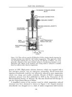
the safety of the system he arranged a demonstration in which a concentric
cable of his own design was made live at 10,000 volts and a workman drove a
chisel through it. The workman was unhurt and the Board of Trade were
satisfied. The main conductors were concentric copper tubes separated by
paper impregnated with ozokerite wax. They were entirely successful, some
remaining in service until 1933.
The generators, however, were less successful and, to make matters worse
for Ferranti, the Board of Trade would only allow the company to supply a
much smaller area of London than he had hoped. The directors decided to
build only a small part of Ferranti’s planned generating plant, and in 1891 he
resigned from the Corporation.
The Deptford scheme was very ambitious, and although the subsequent
history of electricity supply shows that Ferranti was working on the right lines,
he may well have been more immediately successful if his plans had been
rather more modest.
All public electricity supply systems are now entirely AC, although the last
DC supply in Britain—to a Fleet Street newspaper—remained in use until 1985.
For transmission over long distances DC systems are sometimes preferred.
Very high power mercury arc valves, developed in Sweden in the 1930s,
permit very heavy currents to be rectified, transmitted over a DC line, and
then inverted back to AC. DC transmission is also used when it is desired to
link two AC systems which operate at different frequencies or which operate at
the same frequency but cannot be kept in synchronism. An example of the
former is in Japan, where part of the country operates on 50Hz and part on
60Hz, and the two networks are interconnected through a DC link. The cables
under the English Channel linking the British and French grids also operate on
DC. The first Anglo-French link, opened in 1962, had a capacity of 160MW.
New cables, laid in 1986, with a capacity of 2000MW, are buried in a trench
cut in the sea floor to avoid damage by ships’ anchors or fishermen’s trawls.
ECONOMICS: OFF-PEAK LOADS
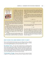
At first the public electricity supply was used almost exclusively for lighting,
but this meant that the system was not used to its maximum efficiency because
the demand was concentrated in to a few hours each day. In 1888, Crompton
produced a graph of the demand for electricity over an average day in which
he showed that the load exceeded 50 per cent of the peak load for only five
hours out of the twenty-four, and exceeded 75 per cent of peak for only about
two hours. The peak load determined the plant costs, and the plant had to be
manned all day and all night. Any load that could be attracted at times other
than the peak hours could therefore be supplied economically at a price barely
greater than the fuel cost.
ELECTRICITY
373
The potential sources for such off-peak loads were electric heating and
cooking, and industrial uses. Electric cooking was vigorously promoted, by
advertising and by articles in the press. Most supply undertakings offered
electricity at reduced price—often half-price—for cooking and hired out
appliances at low rentals. A school of electric cookery was opened in
Kensington, London, in 1894 to promote the idea. In 1912, A.F.Berry opened
his ‘Tricity House’ which combined a restaurant serving 700 meals a day with
a showroom for cooking equipment. Berry also gave lectures on the
advantages of electric cooking, in which he argued that one ton of coal in a
power station could do as much cooking as ten tons of coal delivered to the
house (see Chapter 19).
The reduced prices for electricity used other than for lighting continued into
the 1930s. Today off-peak electricity is still available in the UK at about half-
price, but lighting is now only a fraction of the total demand and the off-peak
hours are in the night.
MEASUREMENT
The rapid progress of electric lighting in the 1880s, created a demand for
practical and reliable measuring instruments. Most important were devices
for measuring voltage and consumption. Accurate voltage measurements
were essential because the life of filament lamps was critically dependent on
the supply voltage. Devices to measure electricity consumption were
required so that customers could be charged according to the electricity
they had used.
The first scientific attempts at electrical measurements were in the
eighteenth century. Electrostatic forces between charged bodies were measured
as early as 1786 when the Revd Abraham Bennet wrote a letter to the Royal
Society describing the gold leaf electroscope. In this two pieces of gold leaf
hanging side by side are in electrical contact with a conductor whose potential
is to be observed. Since the gold leaves become similarly charged they repel
each other, and hang apart at an angle which is a measure of the potential. The
most important of the early workers on electrostatic measurements was
Charles Augustin de Coulomb, who invented the torsion balance electrometer
and used it to establish the inverse square law relating the force of attraction
between charged bodies and the distance between them. Coulomb’s
instrument had a long silk thread supporting a horizontal straw inside a large
glass cylinder. The straw was covered with sealing wax and the silk thread was
fixed to a cap at the top of the cylinder which could be turned. Also inside the
cylinder was a metal ball connected to an external knob which could be
charged. The device was so sensitive that Coulomb could measure a force of a
few milligrammes.
PART TWO: POWER AND ENGINEERING
374
More immediately relevant to the practical business of electricity supply, in
the late nineteenth century Sir William Thompson designed electrostatic
voltmeters which relied on measuring the force of attraction between charged
elements of the instrument. Two patterns were in widespread use. The
quadrant electrometer, which was sold commercially from 1887, had two
vertical sheets of metal with a narrow space between them into which a
pivoted vane was drawn by electrostatic attraction. This instrument could
measure up to 10,000 volts. His multi-cellular meter, made from 1890, had
what were essentially a number of ‘quadrant’ movements side by side on the
same axis, and these meters were used for voltages of a few hundred. A
modified form of the quadrant electrometer, with additional vanes, was used as
a wattmeter.
Until the relatively recent advent of electronic measuring instruments,
most current measurements have depended on measuring the magnetic
force created by a current in a wire. This magnetic force has been balanced
against a controlling force, which may be produced by a spring, by gravity,
or by another magnet. Simple galvanometers, in which a large diameter
coil surrounded a pivoted magnetic needle, with the earth’s magnetic field
providing the controlling force, were made in 1837 by Claude-Servain
Pouillet. Such instruments were accurate and straightforward to use, but
they were bulky and the needle took a long time to come to rest, so
measurements were slow. The electricity supply industry wanted
instruments that were portable, quick to read, and stable in the readings
they gave. In the 1880s there were no really stable magnetic materials, and
simple instruments making use of a magnetized needle had to be
recalibrated from time to time.
A current measuring instrument which did not depend on the vagaries of
magnetic materials was the electrodynamometer. This measured the forces
between current-carrying conductors, so it was really only suitable for high
current work. Being very reliable, however, it was frequently used in
laboratories and for calibrating other instruments. The principle of the
electrodynamometer is due to Wilhelm Weber, who was following up
Ampère’s mathematical study of the forces between currents. A moveable coil,
usually supported by a torsion suspension, hangs within a fixed coil. When
current flows in both coils magnetic forces tend to twist the moveable coil.
Usually the moveable coil is returned to its original position by twisting the top
of the suspension through an angle which is a measure of the current. An
instrument of this kind was used to monitor the operation of the generator in
the first public electricity supply system, at Godalming.
A laboratory version of the electrodynamometer was the Kelvin Ampere
Balance, in which the attractive force between fixed and moving coils was
balanced by a sliding weight on a balance arm. The arrangement was similar to
a balance for weighing. In 1894 two such instruments were held by the Board of
ELECTRICITY
375
Trade as legal standards for the measurement of current. The accuracy was
stated to be within 0.2 per cent—a matter for great satisfaction at the time!
The need for calibration, and all the problems attendant on changing
calibration, can be avoided if the instrument is used simply to determine the
presence or absence of a current. This is the principle of the potentiometer and
bridge measuring circuits.
In the potentiometer, which was first described in 1841, a constant
current was passed through a straight uniform wire placed alongside a
linear scale. The potential between two points on the wire was therefore
proportional to the distance between them, and this could be read from the
scale. Once the scale had been calibrated by means of a voltage standard,
other voltages could be measured accurately. The unknown voltage was
connected through a galvanometer to a length of the potentiometer wire,
and when the galvanometer showed that no current flowed then the
unknown voltage was equal to the voltage across that length of wire.
The potentiometer was used in the bridge circuit described by Wheatstone
in a long Royal Society review paper on electrical measurements in 1843.
(Although it has been known ever since as the Wheatstone bridge, he clearly
attributed it to S.H.Christie.) The bridge circuit was intended for comparing
resistances. An unknown resistance and a standard were connected in series,
carrying the same current, and in parallel with a potentiometer. A
galvanometer was used to determine the point on the potentiometer wire at
which the voltage was the same as at the junction of the two resistances, and
the ratio of the resistances was then the same as the ratio of the two sections of
the potentiometer.
The rapid progress in electric lighting around 1880 created a demand for
direct reading instruments. The new filament lamps were far more critically
dependent on the supply voltage than the older arc lamps, which could tolerate
wide fluctuations without damage. The first practical moving iron ammeter
was devised by Professors W.E.Ayrton and John Perry in 1879. It had an iron
core which was drawn into a circular coil carrying the current to be measured.
In the ‘magnifying’ version the core was restrained by a spring wound helically
from flat metal strip. As the spring was stretched the free end rotated, turning
the pointer. Other moving iron instruments of the period included Schuckert’s,
in which an asymmetrically mounted piece of soft iron was made to twist by
the magnetic field within a current-carrying coil.
The moving coil meter, with a light coil hanging in the annular air-gap
between the poles of a permanent magnet and an iron cylinder, was
devised by J.A.d’Arsonval. Such instruments were first made on a large
scale by the Weston Electrical Instrument Company of New Jersey. Weston
introduced the idea of ‘damping’ the movement by mounting the coil on a
copper former, so that its motion was damped by eddy currents and it
came to rest quickly when a reading was taken. He also used jewelled
PART TWO: POWER AND ENGINEERING
376
bearings to reduce friction. The unipivot instrument, in which the moving
parts are carried on a single bearing to give further reduced friction and
greater sensitivity, was introduced by the London instrument-maker
R.J.Paul in 1903.
Hot-wire instruments make use of the fact that a wire expands when heated.
Philip Cardew designed the first commercial hot-wire instrument in 1883. It
was reliable and accurate, but rather unwieldy, having three metres of
platinum-silver wire stretched over pulleys in a tube almost a metre long. One
end of the wire was fixed, the other held taut by a spring and connected by
gearing to a pointer. The hot-wire principle was adapted by Hartmann and
Braun in the 1890s to produce a more manageable instrument. They utilized
the sag of a taut wire rather than its change in length. The pointer of their
instrument was driven by a wire attached to the middle of the current-carrying
wire and pulling it sideways.
Arthur Wright, the engineer of the Brighton electricity undertaking (see p.
370), made the first recording meter about 1886 to monitor the load on his
system. He used a strip of paper coated with lampblack which was pulled
along by clockwork and marked by a pointer on a simple moving iron
ammeter.
Commercial electricity supply required meters to measure the energy
consumed, so that customers could be charged accordingly, although a few
early systems simply charged according to the number of lamps connected.
Edison made electrolytic meters, in which the current to be measured passed
through a cell containing two zinc plates in zinc sulphate solution. The plates
were weighed periodically to measure the transfer of zinc and hence the
current that had flowed.
The first direct reading supply meter was devised by Ayrton and Perry,
though usually known as the Aron meter after the man who improved and
then manufactured it. These instruments made use of the fact that the speed of
a pendulum clock depends on the force of gravity. Two pendulum clocks were
coupled together through a differential gearing connected to dials which
showed the difference in ‘time’ measured by each clock. Coils were arranged
adjacent to the iron pendulum bobs so that the apparent force of gravity varied
in accordance with the supply being measured.
Most energy meters have what is in effect an electric motor driving a disc
which is restrained by an eddy current brake. The motor torque is arranged
to be proportional to the electrical energy passing; the braking torque is
proportional to speed. The total number of revolutions of the disc is then a
measure of the energy consumed. Elihu Thomson, born in England but
brought up in the USA, devised the first motor meter in 1882. He founded
the Thomson-Houston company in 1879, jointly with his former teacher
E.J.Houston, to make arc lighting equipment, but they soon expanded into
the whole range of electrical manufactures. Ferranti’s mercury motor meter
ELECTRICITY
377
had a copper disc rotating in a bath of mercury, with current flowing radially
in the disc.
The Edison, Thomson and Ferranti meters described were essentially DC
instruments (although Thomson’s would work on AC). After the invention of
the induction motor (see p. 384) induction type instruments were adopted for
all AC systems and are now used in virtually all electricity supplies.
With alternating current systems there was interest in the nature of the
wave-forms involved. A simple contact operated synchronously with the
supply by a cam made it possible to monitor the supply voltage (or current) at
any specific point in the cycle, and by taking a series of such measurements it
was a simple though tedious process to build up a picture of the waveform.
Wheatstone had developed the method in the course of his telegraph
researches, and the idea was reinvented by Joubert in 1880 when studying the
behaviour of arc lighting circuits. A mechanical oscillograph which would give
a visual display of a complete waveform was suggested in 1892 but only
achieved in 1897 when William du Bois Duddell succeeded in making a
galvanometer whose movement was light enough to follow the variations of an
alternating current waveform. In another field, medicine, such instruments
were developed to study the electrical action of the heart.
The discovery of the electron in 1897 led to the cathode ray tube. Tubes
were made which produced a beam of electrons on a screen and could deflect
the beam in two axes at right angles. Circuits were developed to give a
deflection varying with time on one axis. The voltage being studied was then
applied to deflect the beam in the other axis, and a complete waveform drawn
out on the screen. A review of such instruments published by the Institution of
Electrical Engineers in 1928 gave more space to mechanical than to cathode
ray oscilloscopes, but during the 1930s the cathode ray instrument completely
replaced the mechanical.
The first internationally agreed electrical standards were drawn up at the
International Congress of Electricians that met in Paris in 1881. Before that
many workers used their own standards, though the British Association had
been considering national standards for some years. The Congress defined
units for resistance, current and voltage, and since that time electrical science
and engineering has benefited from universally accepted standards of
measurement. This work is now the responsibility of the International
Electrotechnical Commission, in Geneva.
ELECTROMAGNETIC ENGINES
The story of the electric motor really begins with Oersted’s discovery in 1819
that a compass needle could be deflected by an electric current. In 1821, Michael
Faraday showed that it was possible to produce continuous rotary motion by
PART TWO: POWER AND ENGINEERING
378
electromagnetism (see p. 355). During the nineteenth century many machines
were designed that produced mechanical motion from electromagnetic effects,
collectively known as ‘electromagnetic engines’. One early machine was made by
William Sturgeon in 1832, and it was probably the first electromagnetic engine
to be put to practical use—to turn a roasting spit. Sturgeon’s machine had a
vertical shaft carrying two compound permanent magnets, one at the top, one at
the bottom, with their north poles pointing in opposite directions. As the shaft
turned, the ends of the permanent magnets passed close to the poles of the four
vertical electromagnets fixed on the base board. The commutator was an
elaborate arrangement with two concentric mercury cups carried round by the
shaft, into which wires dipped, and a horizontal disc cut into four quadrants,
with wiper arms pressing on them. Another early but little known maker of
electromagnetic engines was Sibrandus Stratingh, a medical doctor and Professor
of Chemistry at Groningen in the Netherlands, who wanted to make an electric
road vehicle. In 1835 he constructed a table-sized model, but he never achieved a
full-size version. Like a number of other early inventors, however, he did make
an electric boat and he managed to take his family in a boat, electrically
powered, in 1840.
The first person to obtain patents for electromagnetic engines was Thomas
Davenport. He patented a machine in the USA in 1837, and later the same
year obtained an English patent also. A model of his machine, now in the
Smithsonian Institution in Washington, has a rotor consisting of four coils on a
cruciform frame fixed to a vertical shaft. Opposite pairs of coils are connected
in series and the ends of the wires go to simple brushes which press on a two-
part commutator consisting of two semi-circular pieces of copper. The battery
is connected to the copper pieces. The stator is two semi-circular permanent
magnets with their like poles adjacent.
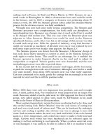
Another American inventor was W.H.Taylor, who exhibited a motor in
London in 1840. Taylor’s machine was written up enthusiastically in the
Mechanics Magazine (see Figure 6.9). The construction was quite simple. An
arrangement of four electromagnets on a frame surrounded a wooden wheel
with seven soft iron armatures around its edge. A simple commutator on the
axis switched on each of the four electromagnets in turn. Taylor claimed that
earlier ideas for electromagnetic engines had depended on reversing the
polarity of electromagnets. He said that his invention was the idea of switching
the magnets so that they were simply magnetized and demagnetized, but not
reversed in polarity. It seems that he realized that it took a significant time to
reverse the polarity of an iron-cored electromagnet.
The Scotsman Robert Davidson made motors which also operated by
switching the electromagnets on and off, not reversing them. In the winter of
1841–42 the Royal Scottish Society of Arts gave him financial help with his
experiments, and in September 1842 he made an electrically driven carriage
which ran on the Edinburgh and Glasgow railway. The four-wheeled carriage
ELECTRICITY
379
Figure 6.9: Engraving of Taylor’s electromagnetic engine.
Reproduced from Mechanic’s Magazine, 9 May 1840.
Figure 6.10: Electromagnetic engine by Wheatstone at the time Taylor’s machine
was exhibited.
PART TWO: POWER AND ENGINEERING
380
was nearly 5m long and weighed about 5 tonnes. The motors were wooden
cylinders on each axle with iron strips fixed on the surface. There were
horseshoe magnets on either side of the cylinder which were energized
alternately through a simple commutator arrangement on the axis. The
batteries, a total of 40 cells each with a zinc plate between two iron plates, were
ranged at each end of the carriage. The plates could be raised out of the
wooden troughs containing the electrolyte by a simple windlass. The carriage
could run at about 6.5kph (4mph) on level track. There is no contemporary
record of the distance actually travelled by the vehicle: presumably it did not
actually travel all the way from Edinburgh to Glasgow. In 1839 the Tsar gave a
grant to Professor M.H.Jacobi of St Petersburg for work on an electric motor,
probably the first government grant ever given for electrical engineering
research. In a letter to Michael Faraday, Jacobi described how he had arranged
for an electromagnetic engine to drive the paddlewheels on a boat and
travelled for days with ten or twelve people aboard on the River Neva. When
supplied from a battery of 128 Grove cells, the vessel travelled at about 4kph.
In some cases enough data is given in contemporary records for the
efficiency of these machines to be calculated, and figures of 10 to 20 per cent
are obtained. The efficiency of electromagnetic engines was possibly a matter
of some interest in the 1840s. In 1843, Charles Wheatstone was describing a
variety of electrical devices in a paper to the Royal Society. One was the
rheostat, which developed initially as a measuring device, but Wheatstone said
that it could be used for controlling the speed of a motor; he also said,
wrongly, that a rheostat in series with a motor could control its speed without
any loss of efficiency.
In 1849 the United States Commissioner of Patents, Thomas Ewbank,
included some thoughts on the subject of electric motors in his annual report
to Congress. He said: ‘The belief is a growing one that electricity…is ordained
to effect the mightiest of revolutions in human affairs.’ He referred to various
experiments with electric motors and then continued, somewhat
pessimistically, ‘but these experiments, interesting as they certainly were, have
brought no marked results, nor afforded any high degree of encouragement to
proceed. It might be imprudent to assert that electromagnetism can never
supersede steam, still, in the present state of electrical science the desideratum
is rather to be hoped for than expected.’ Ewbank’s pessimism was not shared
by Congress. In 1850 the United States Congress gave $20,000 to Professor
Charles Page of Massachusetts, to develop electromagnetic engines, apparently
with the navy mainly in mind. In a report to the Secretary of the Navy, Page
said that he had made machines of one and four horsepower and asked for a
grant to build a machine of 100hp.
The most ingenious of all the early electromagnetic engines must surely be
Allan’s machine made in 1852. This is basically a reciprocating engine with
four cranks and four ‘piston rods’. Each piston rod carries four armatures
ELECTRICITY
381
which press on collars on the rod but are not otherwise fixed to it. There are
16 sets of coils, one for each armature, and the coils are energized one at a time
by a commutator. Each electromagnet is therefore energized for 1/16 of a
revolution. As each armature reaches its electromagnet it is stopped by it, while
the piston rod continues its travel.
All these machines were, in any commercial sense, failures. They were
entirely dependent on expensive chemical batteries, but if that were the only
reason then the electromagnetic engine would have flourished when
generators made electricity readily available in the 1880s. In modern
terminology these engines were all ‘magnetic’ machines which depend on
direct magnetic attraction between stator and rotor. Most modern motors,
such as the induction motor (see p. 384), are electromagnetic machines in
which the fields on one side of the air gap generate currents on the other.
Conventional machine theory tells us that magnetic machines get better as
they get smaller, while electromagby about 1880, although no theoretical
reasoning had been set out.
PRACTICAL ELECTRIC MOTORS
The fact that the machines used as generators could be used also as motors
was recognized quite early. The Siemens brothers, for example, noted in 1872
that the ‘small rotating machine runs just as well as a motor as it does as a
generator’. The firm of Siemens & Halske set out to find customers requiring
electric power transmission. The first public exhibition of the electrical
transmission of power by means of a generator and motor was probably the
demonstration at the Vienna Exhibition in 1873. There the Gramme Company
showed two identical machines linked by wires but 500m apart; one was used
as a generator, the other was used as a motor driving a pump. Similar
demonstrations were given at other exhibitions in the USA and in Britain in
the following few years. By 1874, Gramme had electrically-driven machinery
in his Paris factory—though he used a single large motor driving a line shaft, as
in a steam powered factory, not an individual motor for each machine.
Several exhibitors at the first International Electrical Exhibition, held at
Paris in 1881, demonstrated motors. Marcel Deprez, for example, had a
motordriven sewing machine, lathes, a drill and a printing press. Siemens
exhibited a lift within the building and a tram running towards it along the
Champs-Elysées.
One of the first Gramme machines to be sold as a motor was used to drive
a conveyor for sugar beet in a factory at Sermaize, France. It was so successful
that in May 1879 the factory owners, Messrs Chrétien & Félix, decided to try
electric ploughing. The plough was hauled across a rectangular field by ropes
between two wagons, each carrying a motor and a winding drum.