mobile communications engineering - theory and applications, second edition
Bạn đang xem bản rút gọn của tài liệu. Xem và tải ngay bản đầy đủ của tài liệu tại đây (4.93 MB, 672 trang )
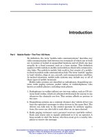
Introduction
Part I Mobile Radio—The First 100 Years
By definition, the term “mobile-radio communications” describes any
radio communication link between two terminals of which one or both
are in motion or halted at unspecified locations and of which one may
actually be a fixed terminal such as a base station. This definition
applies to both mobile-to-mobile and mobile-to-fixed radio communica-
tion links. The mobile-to-mobile link could in fact consist of a mobile-
to-fixed-to-mobile radio communication link. The term “mobile” applies
to land vehicles, ships at sea, aircraft, and communications satellites.
In tactical situations, mobile-radio systems may include any or all of
these types of mobile terminals.
Mobile-radio systems are classified as radiophones, dispatching sys-
tems, radio paging systems, packet radios, or radiotelephones (also
known as mobile phones), including train phones.
1. Radiophones (or walkie-talkies) are two-way radios, such as CB (cit-
izens band) radios, which are allocated 40 channels for anyone to use
whenever the channels are free. This system affords no privacy to
the user.
2. Dispatching systems use a common channel. Any vehicle driver can
hear the operator’s messages to other drivers in the same fleet. The
drivers can talk only to the control operator. In military applica-
tions, the users can also talk to each other on an open channel.
3. Radio paging customers carry personal receivers (portable radios).
Each unit reacts only to signals addressed to it by an operator. A
beep sounds to alert the bearer, who then must go to a nearby tele-
phone to receive the message.
1
Downloaded from Digital Engineering Library @ McGraw-Hill (www.digitalengineeringlibrary.com)
Copyright © 2004 The McGraw-Hill Companies. All rights reserved.
Any use is subject to the Terms of Use as given at the website.
Source: Mobile Communications Engineering
4. Packet radio requires a form of multiple-access control that permits
many scattered devices to transmit on the same radio channel with-
out interfering with each other’s transmissions. Packet radios can be
configured as either mobile or portable terminals. This system may
become important in the future.* Each terminal is attached to a
transmission control unit equipped with a radio transmitter and
receiver. The data to be transmitted are formed into a “packet” within
the transmission control unit. The packet contains the addresses of
the receiving location and the originating terminal. A receiving
device receives any packet addressed to it and transmits an acknowl-
edgment if the packet appears to be free of error. The sending station
waits a predetermined period for the acknowledgment. If it does not
receive an acknowledgment, it transmits the packet again. For exam-
ple, CDPD (cellular digital packet data) is a packet radio system.
†
5. Radiotelephones include MTS (Mobile Telephone Service), IMTS (Im-
proved Mobile Telephone Service), the Metroliner telephone, TACS
(total access communication system),
†
and AMPS (Advanced Mobile
Phone Service).
†
The Metroliner telephone is briefly discussed here,
and the other types of radiotelephones are described, in greater detail,
in subsequent paragraphs. The Metroliner telephone operates in the
400-MHz frequency range on the high-speed train between New York
and Washington, D.C. The 225-mi railway distance is divided into
nine zones. Each zone has a fixed radio transceiver located adjacent to
the track right-of-way. As a train moves from one zone to another, calls
that are in progress must be automatically switched from one fixed
radio transceiver to the next without the customer’s being aware of
any changes or interference in communication.
6. Digital Cellular
†
and PSC (personal communication service)
†
are for
high capacity and data transmission. Digital Cellular in Europe is
called GSM (Global System Mobile), a standard system using TDMA
(time division multiple access). PCS is a cellular-like system applied
at 1.8–1.9 GHz instead of 800–900 MHz for cellular. Other than that,
the system protocols are the same as cellular systems. Digital cellu-
lar in North America has two standards: IS-136 (TDMA) and IS-95
(CDMA). Digital cellular in Japan is called PDC (personal digital
phone), a TDMA system.
7. TDD (Time Division Duplexing) systems
†
such as DECT (digital
European cordless telephone), PHS (personal handy-phone system),
2 Introduction
* S. Fralick and J. Garrett, “Technology for Packet Radio,” AFIPS Conf. Proc., vol. 44,
1975, AFIPS, Montvale, N.J.; and R. E. Kahn, S. A. Gronemeyer, J. Burchfield, and R. C.
Kunzelman, “Advances in Packet Radio Technology,” Proc. IEEE, vol. 66, no. 11, Novem-
ber 1978, pp. 1468–1496.
†
W. C. Y. Le e, Mobile Cellular Telecommunications, Analog and Digital Systems, 2d ed.
McGraw Hill Co., 1995.
Downloaded from Digital Engineering Library @ McGraw-Hill (www.digitalengineeringlibrary.com)
Copyright © 2004 The McGraw-Hill Companies. All rights reserved.
Any use is subject to the Terms of Use as given at the website.
Introduction
and PACS (personal access communication system) use one fre-
quency for both transmission and reception on a time-sharing basis.
These systems are for low mobility and in-building communications.
8. Mobile Broadband Systems* will be the future public land mobile
telecommunication system (FPLMTS). It will operate at a higher
spectrum band (20–60 GHz), using ATM (asynchronous transfer
mode) for broadband packet switching, and it will be compatible
with the B-ISDN (broadband ISDN). It will be the future wireless
information superhighway system.
Let’s pause momentarily to review some of the historical highlights
of mobile-radio communication. The first practical use of mobile-radio
communication was demonstrated in 1897 by Marchese Guglielmo
Marconi, who is credited with first successfully establishing radio
transmission between a land-based station and a tugboat, over an 18-
mi path. The following summary shows some of the important mile-
stones in the history of mobile-radio communication:
1880: Hertz—Initial demonstration of practical radio communication
1897: Marconi—Radio transmission to a tugboat over an 18-mi path
1921: Detroit Police Department—Police car radio dispatch (2-MHz
frequency band)
1932: New York Police Department—Police car radio dispatch (2-MHz
frequency band)
1933: FCC—Authorized four channels in the 30- to 40-MHz range
1938: FCC—Ruled for regular service
1946: Bell Telephone Laboratories—152 MHz (simplex)
1956: FCC—450 MHz (simplex)
1959: Bell Telephone Laboratories—Suggested 32-MHz band for
high-capacity mobile-radio communication
1964: FCC—152 MHz (full duplex)
1964: Bell Telephone Laboratories—Active research at 800 MHz
1969: FCC—450 MHz (full duplex)
1974: FCC—40-MHz bandwidth allocation in the 800- to 900-MHz
range
1981: FCC—Release of cellular land mobile phone service in the 40-
MHz bandwidth in the 800- to 900-MHz range for commercial oper-
ation
Introduction 3
*W.C.Y.Lee,Mobile Cellular Telecommunications,Analog and Digital Systems, 2d ed.
McGraw Hill Co., 1995.
Downloaded from Digital Engineering Library @ McGraw-Hill (www.digitalengineeringlibrary.com)
Copyright © 2004 The McGraw-Hill Companies. All rights reserved.
Any use is subject to the Terms of Use as given at the website.
Introduction
1981: AT&T and RCC (Radio Common Carrier) reach an agreement
to split 40-MHz spectrum into two 20-MHz bands. Band A belongs to
nonwireline operators (RCC), and Band B belongs to wireline opera-
tors (telephone companies). Each market has two operators.
1982: AT&T is divested, and seven RBOCs (Regional Bell Operating
Companies) are formed to manage the cellular operations.
1982: MFJ (modified final judgment) is issued by the government
DOJ. All the operators were prohibited to (1) operate long-distance
business, (2) provide information services, and (3) do manufacturing
business.
1983: Ameritech system in operation in Chicago
1984: Most RBOC markets in operation
1986: FCC allocates 5 MHz in extended band
1987: FCC makes lottery on the small MSA and all RSA licenses
1988: TDMA voted as a digital cellular standard in North America
1992: GSM operable in Germany D2 system
1993: CDMA voted as another digital cellular standard in North
America
1994: American TDMA operable in Seattle, Washington
1994: PDC operable in Tokyo, Japan
1994: Two of six broadband PCS license bands in auction
1995: CDMA operable in Hong Kong
1996: U.S. Congress passes Telecommunication Reform Act Bill.
“Apparently anyone can get into anyone else’s business.”
1996: The auction money for six broadband PCS licensed bands (120
MHz) almost reaches 20 billion U.S. dollars.
1997: Broadband CDMA considered as one of the third-generation
mobile communication technologies for UMTS (universal mobile
telecommunication systems) during the UMTS workshop conference
held in Korea.
In 1970, the FCC allocated the following frequencies for domestic
public mobile-radio use on land:
Number
of Channel Total
Base transmit Mobile transmit channels spacing bandwidth Name
35.26–35.66 MHz 43.26–43.66 MHz 10 40 kHz 0.8 MHz MTS
152.51–152.81 MHz 157.77–158.07 MHz 11 30 kHz 0.6 MHz IMTS (MJ)
454.375–454.65 MHz 459.375–459.65 MHz 12 25 kHz 0.55 MHz IMTS (MK)
4 Introduction
Downloaded from Digital Engineering Library @ McGraw-Hill (www.digitalengineeringlibrary.com)
Copyright © 2004 The McGraw-Hill Companies. All rights reserved.
Any use is subject to the Terms of Use as given at the website.
Introduction
Although a total of 33 channels are provided for within these fre-
quency allocations, the actual number of channels used in a specified
area is much smaller on account of restrictions imposed by prevailing
FCC regulations, which are explained later on.
In 1974, the FCC allocated a 40-MHz bandwidth in the 800- to 900-
MHz frequency region for mobile telephone use. During the initial trial
tests, it was utilized as follows:
Number of Channel Total
Base transmit Mobile transmit channels spacing bandwidth
870–890 MHz 825–845 MHz 666 30 kHz 40 MHz
The Bell Telephone System used this narrow band of frequencies in
trial tests of its new, high-capacity Advanced Mobile Phone Service
(AMPS), which is designed for use in a cellular planned network.
Because the system design is based on the reuse of allocated frequen-
cies, the number of customers served is greatly increased; hence the
term “high-capacity” system. Part II of this introduction describes a
cellular system in greater detail.
By 1976, the Bell System served approximately 40,000 mobile-
telephone customers within the United States. Of this number, 22,000
were able to dial directly, whereas 18,000 required operator assistance
to place a call. The various systems that serve mobile radiotelephones
are classified according to their assigned frequency range. For exam-
ple, the MJ system operates in the 150-MHz range, whereas the MK
system operates in the 450-MHz range. Each system can provide from
1 to as many as 12 channels, with FCC regulations requiring that 12
channels of an MK system serve an area of 50 miles in diameter.
To illustrate how few channels are available and how overloaded
they are, in 1976 the New York Telephone Company (NYTC) operated
6 channels of the MJ system serving 318 New York City mobile-
telephone subscribers, approximately 53 customers per channel, and
there were 2400 applicants wait-listed for MJ mobile-telephone ser-
vice. NYTC also operated six MK channels serving 225 customers,
approximately 38 customers per channel, and 1300 applicants were
wait-listed for MK mobile-telephone service. New York City was lim-
ited to only six MK channels out of the maximum of 12 available
because of the FCC regulation requiring that 12 channels serve an
area of 50 miles in diameter.
In 1976, there were a total of 1327 mobile-telephone systems in oper-
ation across the United States. The Bell System operated 637 mobile-
telephone systems within its coast-to-coast network, whereas 690 were
operated by independent telephone companies. The market demand for
mobile-telephone service is already much greater than the existing
Introduction 5
Downloaded from Digital Engineering Library @ McGraw-Hill (www.digitalengineeringlibrary.com)
Copyright © 2004 The McGraw-Hill Companies. All rights reserved.
Any use is subject to the Terms of Use as given at the website.
Introduction
available supply and is increasing very rapidly because of the great,
undisputed popularity of CB radio, which is very busy and congested,
with only 40 assigned operating channels (26.96 to 27.41 MHz). When
the new, cellular mobile-radio systems are fully operational across the
United States, high-capacity direct-dialing service at reasonable cost
will entice large numbers of CB radio users to subscribe to mobile
radiotelephone. The obvious advantages of mobile radiotelephone over
the heavily saturated CB radio channels are:
1. Direct-dialing features equivalent to those offered to fixed-telephone
subscribers
2. Absolute privacy of communication, with greatly improved quality
3. An extended range of communication utilizing the total switching
resources of the commercial telephone networks
4. A theoretically unlimited number of communication channels that
can be provided
In this book, the theory and analyses are aimed at the mobile-to-fixed
radio communication links that are designed to fit the cellular require-
ments of the VHF and UHF mobile-radiotelephone systems of the 1980s
and that operate in the 30-MHz to 1-GHz mobile-radio frequency ranges.
For systems operating above 1 GHz, atmospheric conditions such as
moisture and climatic effects must be taken into consideration. These
effects are minimal at operating frequencies below 1 GHz. Below 30
MHz, path loss and signal fading are not severe; but since there are few
mobile-radio frequency allocations in this region of the radio spectrum,
the primary emphasis of this book is on the design of 30-MHz to 1-GHz
mobile radio.
Looking toward the future, the portable telephone and ultimately a
pocket telephone are potential product designs that will share mobile-
radiotelephone transmission facilities. Some of the major problems
that must be solved before these designs are realized are the limita-
tions of battery size, weight, and power capacity; radiation safety haz-
ards to the user; and signal interference problems unique to the
portable-telephone user’s environment.
Part II Cellular Network Planning
The future of mobile-radiotelephone communication is dependent upon
techniques of network planning and mobile-radio equipment design
that will enable efficient and economical use of the radio spectrum. One
possible solution to the problem of meeting the steadily increasing cus-
tomer demand for mobile-radiotelephone service, within the limitations
6 Introduction
Downloaded from Digital Engineering Library @ McGraw-Hill (www.digitalengineeringlibrary.com)
Copyright © 2004 The McGraw-Hill Companies. All rights reserved.
Any use is subject to the Terms of Use as given at the website.
Introduction
of available FCC frequency allocations, is to develop a workable plan for
reusing the assigned channels within each band of frequencies. To
encourage the mobile-radiotelephone industry in its development of
advanced high-capacity systems, the FCC in 1974 allocated a 40-MHz
bandwidth in the 800- to 900-MHz frequency range for this purpose.
Subsequent design research and trial tests conducted by the Bell Tele-
phone Laboratories concluded that high-capacity systems based on the
reuse of assigned channel frequencies in a cellular planned network are
a practical solution. The system evolving from this work is known as the
Advanced Mobile Phone Service (AMPS), and its functional capabilities
are described in the following paragraphs.
AMPS service features*
In describing the service features of the AMPS, our primary area of
interest is that of land mobile telephone service, which includes all of
the features ascribed to normal telephone service to the extent that
such services are compatible with the special characteristics of the
mobile environment. This does not preclude the AMPS from providing
other mobile-radio services, such as those services associated with
direct dispatch, air-to-ground, and other types. Land mobile telephone
service is offered as a subscriber service for privately owned vehicles,
and as a public telephone service on commercial ground carriers such as
buses and trains. We know from past experience that the special char-
acteristics of the mobile-radio environment can have an adverse effect
upon radio propagation, and consequently can affect the quality of the
services provided. It is therefore essential to know the cause, extent,
and methods for minimizing these effects in order to improve the qual-
ity and reliability of mobile-radiotelephone communication. The effects
of the mobile environment on mobile-radio performance are further
examined in later chapters covering the theory of functional design.
Radio enhancement techniques As previously mentioned, the FCC has
allocated a 40-MHz bandwidth in the 800- to 900-MHz frequency range
for high-capacity mobile radiotelephone service. On the basis of the con-
cept of cellular network planning, the 40-MHz bandwidth is separated
into a 20-MHz base-station transmit band in the 870- to 890-MHz range
and a mobile-radio 20-MHz transmit band in the 825- to 845-MHz
range. The total 40-MHz bandwidth is further subdivided into 666 two-
way channels, each channel consisting of two frequencies having chan-
Introduction 7
* “Advanced Mobile Phone Service,” special issue, Bell System Technical Journal, vol.
58, January 1979.
Downloaded from Digital Engineering Library @ McGraw-Hill (www.digitalengineeringlibrary.com)
Copyright © 2004 The McGraw-Hill Companies. All rights reserved.
Any use is subject to the Terms of Use as given at the website.
Introduction
nel bandwidths of 30 kHz each. To enable frequency separation between
channels within a given area, the 666 channels are arranged for two
operators in the form of a distribution matrix, as illustrated in Fig. I.1.
In Fig. I.1, the Block A and Block B operators have 333 channels each.
Among 333 channels, 21 channels indicated in Fig. I.1 are the setup
channels. The matrix can be considered to be 21 sets of channels.
To simplify distribution, the 21 sets are arranged into 3 groups of 7
and assigned suffix letters A, B, and C, respectively. The distribution of
channels and channel frequencies obtained by this arrangement
ensures that assignments within one geographic cell area will not inter-
fere with channels assigned in adjacent cell locations. Cells that are
separated by a minimum distance determined by propagation variables
can simultaneously use the same channels with no risk of interference.
The sample cell structure shown in Fig. I.1 illustrates the method for
assigning channels among contiguous cell locations.
A system operator serving a particular population center, such as a
major city and its surrounding suburban communities, could provide
mobile-radio coverage to large numbers of users based on cellular reuse
of assigned channel frequencies. The basic cell structure is conceptu-
ally hexagonal in shape and can vary in size according to the number
8 Introduction
Figure I.1 Frequency-management chart.
Downloaded from Digital Engineering Library @ McGraw-Hill (www.digitalengineeringlibrary.com)
Copyright © 2004 The McGraw-Hill Companies. All rights reserved.
Any use is subject to the Terms of Use as given at the website.
Introduction
of channels, traffic variables, and the effectiveness of propagation-
enhancement techniques. For purposes of explanation, we will tem-
porarily disregard cell size. A typical area divided into cells is shown in
Fig. I.2. Each block of seven cells is repeated in such a manner that cor-
responding numbered cells in adjacent seven-cell blocks are located at a
predetermined distance from the nearest cell having the same number.
Correspondingly, the 20-MHz-bandwidth radio spectrum is divided into
seven disjoint sets, with a different set allocated to each one of the seven
cells in the basic block. With a total of 333 channels in 21 sets available,
it is possible to assign as many as three sets to each of the seven cells
constituting the basic block pattern.
For blanket coverage of cell areas, each cell site is installed at the cen-
ter of the cell (the dotted-line cell) and covers the whole cell, as shown in
Fig. I.3. There is another way of looking at the locations of the cell sites.
The three cell sites are installed, one at each alternate corner of the cell
and cover the whole cell, as shown in Fig. I.3. In both cases, although the
boundary of a cell is defined differently, the cell sites do not need to be
moved. For convenience, the cells illustrated in Fig. I.3 are pictured as
hexagonal in shape. In actual practice, the cell boundaries are defined by
the minimum required signal strength at distances determined by the
reception threshold limits. In the AMPS, base stations are referred to as
cell sites because they perform supervision and control in addition to the
transmitting and receiving functions normally associated with the con-
ventional base station. Mobile-telephone subscribers within a given cell
are assigned to a particular cell site serving that cell simply by the
Introduction 9
Figure I.2 Basic cell block: R = radius of each
cell; D = distance between two adjacent
frequency-reuse cells; K = number of cells in a
basic cell block. K = 7 in this illustration, and
D/R = 4.6.
K =
(D/R)
2
ᎏ
3
Downloaded from Digital Engineering Library @ McGraw-Hill (www.digitalengineeringlibrary.com)
Copyright © 2004 The McGraw-Hill Companies. All rights reserved.
Any use is subject to the Terms of Use as given at the website.
Introduction
assignment of an idle channel frequency under the control of the mobile-
telephone switching office (MTSO). When a mobile unit crosses a cell
boundary, as determined by the signal reception threshold limits, a new
idle channel frequency is assigned by the new serving cell site.This auto-
matic switching control function is referred to as a “handoff.”
The problems of cochannel interference are avoided by ensuring a
minimum distance between base stations using the same channel fre-
quencies, and by enhancing signal level and reducing signal fading
through the use of diversity schemes. These constraints limit any
potential cochannel interference to levels low enough to be compatible
with the transmission quality of landline networks.
Two forms of diversity are used to enhance radio propagation, thus
improving AMPS cell coverage. These are defined as “macroscopic” and
“microscopic” diversity. Macroscopic diversity compensates for large-
scale variations in the received signal resulting from obstacles and
large deviations in terrain profile between the cell site and the mobile-
telephone subscriber. Macroscopic diversity is obtained by installing
directional antennas, one for each sector of three sectors at the cell cen-
ter, or installing at the alternate corners of cells, as shown in Fig. I.3,
and transferring control to the antenna providing the strongest aver-
age signal from the mobile subscriber in any given time interval. For
example, the three cell-site transmitters serving a particular cell area
would not radiate simultaneously on an assigned channel frequency.
On the basis of a computer analysis of the signals received from the
mobile subscriber at each of the three sites, the one with the strongest
10 Introduction
Figure I.3 Use of inward-directed antennas at alter-
nate cell corners to achieve macroscopic diversity
with respect to large obstructions.
Downloaded from Digital Engineering Library @ McGraw-Hill (www.digitalengineeringlibrary.com)
Copyright © 2004 The McGraw-Hill Companies. All rights reserved.
Any use is subject to the Terms of Use as given at the website.
Introduction
signal would be selected for use as the serving cell site. Periodic analy-
sis of channels in use would determine the necessity for handoff to a
new sector in a cell or an alternate cell site within the cell area (intra-
handoff), or handoff to a cell site in an adjacent cell area (interhandoff).
All of these decisions would be made automatically without the knowl-
edge or intervention of the user or the operator, and without interrup-
tion of the call in progress.
Microscopic diversity compensates for fast variations in the received
signal resulting from multipath fading. Microscopic diversity is obtained
by receiving dual inputs at both the mobile and cell-site receivers. These
dual inputs can be two different frequencies, time slots, antennas, polar-
izations, etc. The diversity schemes associated with the combining tech-
niques are described in subsequent chapters of this book.
Switch planning The cellular mobile-radiotelephone system can be
expected to accommodate the growth of new subscribers in two ways.
First, not all of the channels allocated to a cell are initially placed into
service. As the numbers of mobile subscribers increase and the traffic
intensity increases, transmission facilities for the additional channels
are modularly expanded to keep pace with the demand. Second, as the
number of channels per cell site approaches the maximum within the
channel allocation plan, the area of individual cells can be reduced, thus
permitting more cells to be created with less physical separation but
with increased reuse of assigned channel frequencies. This reconfigura-
tion of the cellular network permits the same number of assigned chan-
nels to adequately serve greater numbers of mobile units within a
greater number of smaller cells. The ideal, customized cellular network
would not be uniformly divided into cells of equal size but would contain
cells of different sizes based on the density of mobile units within the
various cell coverage areas. The concept of variable cell size is illus-
trated in Fig. I.4.
The interface between land mobile units and the commercial tele-
phone landline network is illustrated in Fig. I.5. A call originating from
or terminating at a mobile unit is serviced by a cell site connected via
landlines to a mobile-telephone switching office (MTSO). The MTSO
provides call supervision and control, and extends call access to a com-
mercial telephone landline network via a local central-office (CO) tele-
phone exchange, a toll office, and any number of tandem offices required
to complete the call path. The terminating central office completes the
connection to the called subscriber at the distant location. Two types of
mobile-radio channels are used in setting up a call: paging channels and
communication channels. The mobile unit is designed to automatically
tune to the strongest paging channel in its local area for continuous
monitoring, and to automatically switch to another paging channel
when approaching the threshold transition level of reception.
Introduction 11
Downloaded from Digital Engineering Library @ McGraw-Hill (www.digitalengineeringlibrary.com)
Copyright © 2004 The McGraw-Hill Companies. All rights reserved.
Any use is subject to the Terms of Use as given at the website.
Introduction
The following is a typical call sequence for processing a call from a
fixed-telephone subscriber to a mobile-telephone subscriber. The call
from the fixed-telephone subscriber is originated in the normal manner
of direct dialing under control of the local telephone exchange. The tele-
phone switching network translates the called number and routes the
call to the MTSO in the cell area closest to the called mobile-telephone
subscriber. The terminating MTSO determines whether the number
called is busy or available. If it is busy, the MTSO causes a busy signal
to be returned to the calling party. If the mobile subscriber’s telephone
is available, the called number is broadcast over all paging channels
assigned to cell sites in that area. The called mobile unit automatically
recognizes its number and responds by acknowledgment over the corre-
sponding paging-channel frequency. On the basis of the paging-channel
response, the MTSO will identify the serving cell site and automatically
switch the mobile unit to an idle communication channel from among
the channels allocated to that serving cell site. The MTSO, after select-
ing an idle communication channel, causes the mobile unit to tune to
that channel by means of a data command over it. The incoming call is
connected to the appropriate circuit serving the mobile unit, and a ring-
ing signal is sent to the mobile unit.
12 Introduction
Figure I.4 Tailoring a cell plan to a severe density
gradient. Maximum of 10 channels per cell in
largest cells = 0.625 (=
10
⁄16) voicepaths per unit
area. Maximum of 15 channels per cell in medium
cells = 3.75 (=
15
⁄4) voicepaths per unit area. Maxi-
mum of 25 channels per cell in smallest cells = 25
(=
25
⁄1) voicepaths per unit area.
Downloaded from Digital Engineering Library @ McGraw-Hill (www.digitalengineeringlibrary.com)
Copyright © 2004 The McGraw-Hill Companies. All rights reserved.
Any use is subject to the Terms of Use as given at the website.
Introduction
Each cell site has a locating receiver which monitors all active chan-
nels in discrete time intervals. After having served as the central office
in completing the call setup, the MTSO continues to access the serving
cell’s locating receiver, thereby monitoring the mobile-radio transmis-
sions at prescribed intervals. Should the received average signal
strength drop below the prescribed level in any given time interval, the
MTSO will automatically, and without interruption, switch the call to
whatever idle channel at any cell site serving the mobile unit has the
strongest received signal above the prescribed level. This is the handoff
process, and it can be performed within the same cell or in a new cell.
In the processing of a call originating from a mobile unit, the mobile
unit’s telephone in going off the hook signals a request for service over
the paging channel chosen by its receiver. After the MTSO identifies the
location of the serving cell site, an idle communication channel is
assigned to the mobile unit via that cell site and a dial tone is returned
to the mobile user. The MTSO will perform the services of the central
office in setting up the call and will continue to monitor the received sig-
nal strength of the mobile-radio transmissions from the locating receiver
while the call is in progress, performing handoff whenever required.
In summary, the mobile-radiotelephone user is never involved in or
even aware of the MTSO channel assignment and handoff processes,
Introduction 13
Figure I.5 System block diagram: MTSO =
mobile-telephone switching office; CO = central
office (telephone exchange); CS = cell site.
Downloaded from Digital Engineering Library @ McGraw-Hill (www.digitalengineeringlibrary.com)
Copyright © 2004 The McGraw-Hill Companies. All rights reserved.
Any use is subject to the Terms of Use as given at the website.
Introduction
which are performed automatically under control of the MTSO proces-
sor. In addition to serving as the central office for all calls originating
and terminating at mobile units, the MTSO controls and supervises
the assignment of all communication channels and the quality of radio
transmission over assigned channels at multiple numbers of cell sites.
The MTSO also communicates with other MTSO facilities in much the
same manner as one central office communicates with other central
offices.
Mobile-telephone channels are uniquely different in many respects
from conventional line circuits. Mobile-telephone channels are treated
as trunks by the MTSO and thus appear on the trunk side of the
switching matrix serving the various cell sites. The concept of a typical
mobile-radio communications network is shown in Fig. I.5; however, in
actual practice, there are many more cell sites under the control of each
MTSO and many more MTSO facilities serving the mobile-telephone
community. The existing commercial fixed-telephone network overlies
the mobile-radiotelephone cellular network; the primary interface is
via the MTSO trunking facilities.
Extended spectrum
FCC has allowed an additional 10 MHz for two operators. Each one has
5 MHz, i.e., 2.5 MHz one way. The total number of channels for each
operator is 83. Therefore, the total voice channels increase to 395. The
new channel-numbering scheme is shown in Fig. I.6. The new fre-
quency management for band A (or block A) and band B (or block B) are
shown in Tables I.1 and I.2, respectively.
14 Introduction
Figure I.6 New additional spectrum allocation.
Downloaded from Digital Engineering Library @ McGraw-Hill (www.digitalengineeringlibrary.com)
Copyright © 2004 The McGraw-Hill Companies. All rights reserved.
Any use is subject to the Terms of Use as given at the website.
Introduction
15
TABLE I.1 New Frequency Management (Full Spectrum), Block A
1A 2A 3A 4A 5A 6A 7A 1B 2B 3B 4B 5B 6B 7B 1C 2C 3C 4C 5C 6C 7C
123456789101112131415161718192021
22 23 24 25 26 27 28 29 30 31 32 33 34 35 36 37 38 39 40 41 42
43 44 45 46 47 48 49 50 51 52 53 54 55 56 57 58 59 60 61 62 63
64 65 66 67 68 69 70 71 72 73 74 75 76 77 78 79 80 81 82 83 84
85 86 87 88 89 90 102 103 104 105
106 107 108 109 110 111 123 124 125 126
127 128 129 130 131 132 144 145 146 147
148 149 150 151 152 153 165 166 167 168
169 170 171 172 173 174 186 187 188 189
190 191 192 193 194 195 207 208 209 210
211 212 213 214 215 216 228 229 230 231
232 233 234 235 236 237 249 250 251 252
253 254 255 256 257 258 270 271 272 273
274 275 276 277 278 279 291 292 293 294
295 296 297 298 299 300 312 X X X
313* 314 315 316 317 318 319 320 321 322 323 324 325 326 327 328 329 330 331 332 333
667 668 669 670 671 672 673 674 675 676 677 678 679 680 681 682 683 684 685 686 687
688 689 690 691 692 693 694 695 696 697 698 699 700 701 702 703 704 705 706 707 708
709 710 711 712 713 714 715 716 X 991 992 993 994 995 996 997 998 999 1000 1001 1002
1003 1004 1005 1006 1007 1008 1009 1010 1011 1012 1013 1014 1015 1016 1017 1018 1019 1020 1021 1022 1023
* Boldface numbers indicate 21 control channels for Block A and Block B, respectively.
Downloaded from Digital Engineering Library @ McGraw-Hill (www.digitalengineeringlibrary.com)
Copyright © 2004 The McGraw-Hill Companies. All rights reserved.
Any use is subject to the Terms of Use as given at the website.
Introduction
16
TABLE I.2 New Frequency Management (Full Spectrum), Block B
1A 2A 3A 4A 5A 6A 7A 1B 2B 3B 4B 5B 6B 7B 1C 2C 3C 4C 5C 6C 7C
334* 335 336 337 338 339 340 341 342 343 344 345 346 347 348 349 350 351 352 353 354
355 356 357 358 359 360 361 375
376 377 378 379 380 381 382 396
397 398 399 400 401 402 403 417
418 419 420 421 422 423 424 438
439 440 441 442 443 444 445 459
460 461 462 463 464 465 466 480
481 482 483 484 485 486 487 501
502 503 504 505 506 507 508 522
523 524 525 526 527 528 529 543
544 545 546 547 548 549 550 564
565 566 567 568 569 570 571 585
586 587 588 589 590 591 592 593 594 595 596 597 598 599 600 601 602 603 604 605 606
607 608 609 610 611 612 613 614 615 616 617 618 619 620 621 622 623 624 625 626 627
628 628 630 631 632 633 634 635 636 637 638 639 640 641 642 643 644 645 646 647 648
649 650 651 652 653 654 655 656 657 658 659 660 661 662 663 664 665 666 717 718 719
720 721 722 723 724 725 726 727 728 729 730 731 732 733 734 735 736 737 738 739 740
741 742 743 744 745 746 747 748 749 750 751 752 753 754 755 756 757 758 759 760 761
762 763 764 765 766 767 768 769 770 771 772 773 774 775 776 777 778 779 780 781 782
783 784 785 786 787 788 789 790 791 792 793 794 795 796 797 798 799
* Boldface numbers indicate 21 control channels for Block A and Block B, respectively.
Downloaded from Digital Engineering Library @ McGraw-Hill (www.digitalengineeringlibrary.com)
Copyright © 2004 The McGraw-Hill Companies. All rights reserved.
Any use is subject to the Terms of Use as given at the website.
Introduction
Digital cellular
Digital cellular will share the same spectrum with the analog cellular.
In digital cellular, there are two standards, North American TDMA
(tune division multiple access) and CDMA (code division multiple
access). These two systems will be discussed in Chap. 15.
PCS (Personal Communications Service)
Broadband PCS.
FCC has licensed six broadband PCS bands, totalling
120 MHz in 1.9 GHz. The frequency distribution is shown in Fig. I.7(a),
three 30 MHz licenses and three 10 MHz licenses. Every market can
have six system operators operating on six licenses. Besides, two unli-
censed bands—one for voice (10 MHz) and one for data (10 MHz)—are
also shown in Fig. I.7(a).
There are six possible standard systems:
1. DCS (Digital Cellular System)-1900. A GSM-version system
2. CDMA-1900. A cellular CDMA-version system
3. NA-TDMA-1900. A cellular NA-TDMA (IS-136)-version system
4. Omnipoint. A hybrid system with CDMA, TDMA, and FDMA
5. B-CDMA. A broadband CDMA (5-MHz or 10-MHz) system
6. PACS-1900. Personal Access Communications System, a Bellcore-
developed system
The protocol in each PCS system is in general adapting its correspond-
ing cellular system.
Narrowband PCS. FCC has also licensed three narrowed band PCS for
two-way paging as shown in Fig. I.7(b). There are three kinds of two-
way paging channels:
1. Five 50-kHz channels paired with 50-kHz channels
2. Three 50-kHz channels paired with 12.5-kHz channels
3. Three 50-kHz unpaired channels
In a two-way paging channel, the reverse link (pager to base) has
power limitations and needs an arrangement different than the cellu-
lar system.
Part III Summary—Commercial versus
Military
Mobile communication has been, and continues to be, an essential tacti-
cal requirement for many types of military operations involving mobile
forces. Specific mobile-radiotelephone requirements vary widely because
of different needs and different traditional methods of satisfying such
needs within the several branches of the United States Armed Forces.
Traditional methods were based on military radio-frequency allocations
Introduction 17
Downloaded from Digital Engineering Library @ McGraw-Hill (www.digitalengineeringlibrary.com)
Copyright © 2004 The McGraw-Hill Companies. All rights reserved.
Any use is subject to the Terms of Use as given at the website.
Introduction
in all bands from VLF all the way through SHF, depending upon the par-
ticular transmission medium and the operational environment of the
mobile user. Often, the equipment and methods used were inefficient,
cumbersome to set up and move, wasteful of the assigned radio spec-
trum, and restricted by limitations imposed by design application and
regulatory authority.
As new systems and concepts in military communication evolved from
advances in solid-state digital technology, the role of mobile radiotele-
18 Introduction
901.00 .05 .1 .15 .20 901.25
Five 50-kHz channels paired with 50-kHz channels
940.00 .05 .1 .15 .20 940.25 MHz
901.75
.7625 .7750
901.7875 930.40
Three 50-kHz channels paired with 12.5-kHz channels
.45 .50 930.55 MHz
940.75 .80 .85
Three 50-kHz unpaired channels
940.90 MHz
Figure I.7 (a) Wideband PCS for cellular-like systems; (b) narrowband PCS for two-way
paging systems.
18501800
UV-unlicensed voice
UD-unlicensed date
Name of Band
Band A
Band D
Band B
Band E
Band F
Band C
Unlicensed voice
30 MHz
10
30
10
10
30
10
1850–1865
1865–1870
1870–1885
1885–1890
1890–1895
1895–1910
1910–1915
1930–1945
1945–1950
1950–1965
1965–1970
1970–1975
1975–1990
1925–1930
Unlicensed data 10 1915–1925
Base Rv (MHz) Base Tx (MHz)
Spectrum
Bandwidth
1870 1900 1930 1950 1970 1990
A
15 15 10 15 15 151555
Base Rv
Base Tx
55 5 555
DB E
UV
FEFCCABDUD
(a)
(b)
Downloaded from Digital Engineering Library @ McGraw-Hill (www.digitalengineeringlibrary.com)
Copyright © 2004 The McGraw-Hill Companies. All rights reserved.
Any use is subject to the Terms of Use as given at the website.
Introduction
phone as an integrated extension of the global military switching net-
works became technologically significant. Before long, the advanced mil-
itary systems were using digital modulation techniques in place of the
traditional amplitude- and frequency-modulation techniques for voice
and data transmission. In recent years, there has been considerable
activity in the design and development of spread spectrum systems for
military security applications. The spread-spectrum design concept has
also been applied to military mobile radio. Some of the basic differences
between commercial and military systems that affect the mobile radio
system design approach are summarized in Table I.3.
Introduction 19
TABLE I.3 Mobile Radio: Commercial vs. Military Design Considerations
Commercial Military
1. Voice quality must approach that of normal 1. Communications security and integrity of
speech. error-free transmissions must be ensured.
2. Signaling performance must be equal to 2. Signaling must comply with military signaling
landline telephones. specifications.
3. Designed to minimize interference from 3. In addition to interference from unintentional
predictable, unintentional sources. sources, interference from intentional sources
must be anticipated and counteracted.
4. Compatible with frequencies allocated by the 4. Compatible with frequencies allocated by the
FCC, and often dependent upon FCC approval IRAC (Interdepartment Radio Advisory
of a commercial proposal to use a particular Committee).
frequency band.
5. Base-station site is carefully selected and subject 5. Base-station site is limited to military options
to approval by local government authority. and tactical operational requirements.
6. Base station is a fixed plant installation. 6. Base station is often transportable and
designed for over-the-road hauling.
7. Base-station antenna is designed for optimal 7. Base-station antenna is designed for use under
planned coverage of the area it serves. potentially hostile wartime conditions and for
minimum visibility and quick setup and
teardown.
8. Base station often serves densely populated 8. Base station more often serves sparsely
urban areas. populated field deployment areas.
9. Noise levels based on the worst case for a 9. Noise levels based on tactical wartime
normal environment are predictable. situations require special design
consideration.
10. User expects a full range of customer service 10. Ruggedized construction capable of
features and options. surviving in unfavorable environments.
11. Attractive appearance and styling. 11. Lightweight, simple to operate, and easy to
remove and replace.
12. Designed for theftproof installation. 12. Design must use military-standard parts
meeting military specifications.
13. Mobile-to-base or mobile-to-base-to-mobile 13. Mobile-to-base or mobile-to-mobile.
(for billing purposes).
14. Cost consciousness. 14. High technology initiative.
Downloaded from Digital Engineering Library @ McGraw-Hill (www.digitalengineeringlibrary.com)
Copyright © 2004 The McGraw-Hill Companies. All rights reserved.
Any use is subject to the Terms of Use as given at the website.
Introduction
blank page 20
Downloaded from Digital Engineering Library @ McGraw-Hill (www.digitalengineeringlibrary.com)
Copyright © 2004 The McGraw-Hill Companies. All rights reserved.
Any use is subject to the Terms of Use as given at the website.
Introduction
Chapter
The Mobile-Radio Signal Environment
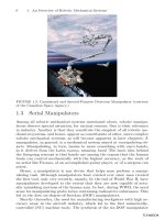
1.1 The Mobile-Radio
Communication Medium
Radio signals transmitted from a mobile-radio base station are not
only subject to the same significant propagation-path losses that are
encountered in other types of atmospheric propagations, but are also
subject to the path-loss effects of terrestrial propagation. Terrestrial
losses are greatly affected by the general topography of the terrain.
The low mobile-antenna height, usually very close to ground level, con-
tributes to this additional propagation-path loss. In general, the tex-
ture and roughness of the terrain tend to dissipate propagated energy,
reducing the received signal strength at the mobile unit and also at the
base station. Losses of this type, combined with free-space losses, col-
lectively make up the propagation-path loss.
Mobile-radio signals are also affected by various types of scattering
and multipath phenomena—which can cause severe signal fading—
attributable to the mobile-radio communications medium. Mobile-radio
signal fading compounds the effects of long-term fading and short-term
fading, which can be separated statistically and are described in Chap.
3. Long-term fading is typically caused by relatively small-scale varia-
tions in topography along the propagation path. Short-term fading is
typically caused by the reflectivity of various types of signal scatterers,
both stationary and moving. Fading of this kind is referred to as “multi-
path” fading.
Propagation between a mobile unit and a base station is most sus-
ceptible to the effects of multipath fading phenomena, because all com-
munication is essentially at ground level. The effects of multipath
phenomena are not significant in air-to-ground and satellite-to-earth-
station communications, because the angle of propagation precludes
21
1
Source: Mobile Communications Engineering
Downloaded from Digital Engineering Library @ McGraw-Hill (www.digitalengineeringlibrary.com)
Copyright © 2004 The McGraw-Hill Companies. All rights reserved.
Any use is subject to the Terms of Use as given at the website.
most types of interference caused by surrounding natural land
features and man-made structures. The major concern in air-to-ground
communication is the Doppler effect resulting from the relatively high
flying speed of the communicating aircraft. The important considera-
tions in satellite-to-earth-station communication are direct-path atten-
uation in space, which severely reduces the level of received signals;
the signal delay time resulting from the long-distance up-down transit;
and the requirement for highly directional earth-station antennas
capable of tracking the satellite beacon.
Generally speaking, the signal strength of a signal transmitted
from a base station decreases with distance when measured at vari-
ous points along a radial path leading away from the base station.
Ideally, signal-strength measurements would be made by monitoring
and recording the signal received by a mobile unit as it moves away
from the base station along a radial route at a constant rate of speed.
This measurement technique would be repeated over many different
radial routes in order to obtain a significant number of readings
that would enable statistical analysis of the overall zone of mobile-
radio coverage for a particular base station. In actual practice, it is
difficult to achieve the ideal conditions for signal-strength measure-
ments, since existing roads must be used and traffic conditions de-
termine the actual rate of travel, necessitating occasional stops along
the way. For optimal radio-signal reception in the mobile-radio use
area, both the base-station antenna and the mobile-unit antenna
should be located at the highest available point along the propaga-
tion path. However, even under the most optimal siting conditions,
there are often hills, trees, and various man-made structures and
vehicles that can adversely affect the propagation of mobile-radio
signals.
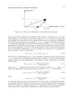
A typical graphic plot of the instantaneous signal strength of a re-
ceived signal as a function of time, or of s(t), is shown in Fig. 1.1(b). The
starting time t corresponds to the starting point x
1
for route x, as shown
in Fig. 1.1(a). The route x is called the mobile path. If it is possible for
the speed V of the mobile unit to remain constant during the recording
period, then s(t) recorded on a time scale can be used for s(x) by simply
changing the time scale into a distance scale, where x = Vt. However, if
the speed of the mobile unit varies during the recording period, then
s(t) must be velocity-weighted in order to obtain a true representation,
as illustrated by s(x) in Fig. 1.1(c). The graph of the instantaneous sig-
nal strength of a received signal as a function of distance, s(x), from the
base station along a particular route is used to calculate the path loss
of that route, even though the graph of s(t) is the actual raw data
obtained from the field.
22 Chapter One
Downloaded from Digital Engineering Library @ McGraw-Hill (www.digitalengineeringlibrary.com)
Copyright © 2004 The McGraw-Hill Companies. All rights reserved.
Any use is subject to the Terms of Use as given at the website.
The Mobile-Radio Signal Environment
Example 1.1 The following example illustrates the procedure for plotting s(t)
from the signal data recorded as the mobile unit is in motion with respect to the
base-station antenna. During the time when signal data are being recorded, a
“wheel-tick” device is used to record the actual speed of the mobile unit on a cor-
responding time scale, as shown in Fig. E1.1.1, where distance is plotted on the y
axis and time is plotted on the x axis.
The Mobile-Radio Signal Environment 23
Figure 1.1 A typical record of data: (a) a typical navigator’s map;
(b) s(t) expressed on time scale; (c) s(t) expressed on distance scale.
(c)
(b)
(a)
Downloaded from Digital Engineering Library @ McGraw-Hill (www.digitalengineeringlibrary.com)
Copyright © 2004 The McGraw-Hill Companies. All rights reserved.
Any use is subject to the Terms of Use as given at the website.
The Mobile-Radio Signal Environment
24 Chapter One
Figure E1.1.1 Sampling points in time corresponding to
unequally spaced samples in length due to the variation of
vehicular speed.
Figure E1.1.2 Converting sampling points from time
frame to distance frame.
Downloaded from Digital Engineering Library @ McGraw-Hill (www.digitalengineeringlibrary.com)
Copyright © 2004 The McGraw-Hill Companies. All rights reserved.
Any use is subject to the Terms of Use as given at the website.
The Mobile-Radio Signal Environment
In the example shown in the figure, the mobile unit has recorded five different
speeds and one complete stop. The y coordinate shows the distance of the mobile
unit from the base-station antenna at any given time along the x coordinate. The
correlation between sampling points in the time frame and those in the distance
frame shows that the speed of the mobile unit was not constant throughout the
period when measurements were being taken.
A different but related perspective is obtained from Fig. E1.1.2, where distance is
plotted along the x axis and time along the y axis. Since the average field
strength at each sampling point is the average of the field-strength measure-
ments within the distance interval, the resultant plot shows that the distribution
along the distance scale is not evenly distributed. It is therefore required that the
engineer conducting the study determine that the distance intervals at which
field-strength samples are recorded are consistent with the speed and motion
characteristics of the mobile unit.
The measurements here were recorded at the mobile receiver as the mobile unit
traveled from the starting point along a route x, as indicated on the map of Fig.
1.1(a). The dotted line in Fig. 1.1(c) represents the average power of the signal
received at the mobile unit as a function of distance, or P(x), for that particular
path. In practice, the average received power at a distance x
1
, P(x
1
), can be
obtained directly, by averaging the instantaneous signal-strength measurements
recorded within an interval of a certain length at a specified distance from the
base station. The methods used to calculate the average received power and to
determine the propagation-path loss at various radial distances along a path are
described in greater detail in Chap. 3.
In the mobile-radio communications environment there are times
when the mobile unit will be in motion, and other times when the mobile
unit will be stationary. When the mobile unit is moving, it moves at var-
ious rates of speed and travels in various directions. As the mobile unit
proceeds along its route, it passes many types of local scatterers, includ-
ing numerous other vehicles in motion.
The presence of scatterers along the path constitutes a constantly
changing environment that introduces many variables that can scat-
ter, reflect, and dissipate the propagated mobile-radio signal energy.
These effects often result in multiple signal paths that arrive at the
receiving antenna displaced with respect to each other in time and
space. When this happens, it has the effect of lengthening the time
allotted to a discrete portion of the signal information and can cause
signal smearing. This phenomenon is referred to as “delay spread.”
Also, the arrival of two closely spaced frequencies with different
time-delay spreads can cause the statistical properties of the two
multipath signals to be weakly correlated. The maximum frequency
difference between frequencies having a strong potential for correla-
tion is referred to as the “coherence bandwidth” of the mobile-radio
transmission path. Coherence correlation then can be avoided by
discretionary assignment of channel frequencies on the basis of fre-
The Mobile-Radio Signal Environment 25
Downloaded from Digital Engineering Library @ McGraw-Hill (www.digitalengineeringlibrary.com)
Copyright © 2004 The McGraw-Hill Companies. All rights reserved.
Any use is subject to the Terms of Use as given at the website.
The Mobile-Radio Signal Environment