USB Complete fourth- P5 pps
Bạn đang xem bản rút gọn của tài liệu. Xem và tải ngay bản đầy đủ của tài liệu tại đây (237.55 KB, 10 trang )
Chapter 1
16
devices. To increase the available bandwidth for USB devices, many PCs have
multiple host controllers, each controlling an independent bus.
$WU5RGGF%QPUKFGTCVKQPU
A USB 3.0 host supports all four speeds. A USB 2.0 host supports low, full, and
high speed. A USB 1.x host supports low and full speeds only. Exceptions
include On-The-Go devices and other special-purpose hosts in embedded sys-
tems, which may support only the speeds needed to access specific peripherals.
A USB 3.0 hub contains both a USB 2.0 hub and a SuperSpeed hub and han-
dles traffic at any speed. SuperSpeed traffic uses the SuperSpeed hub’s circuits
and wires, and other traffic uses the USB 2.0 hub’s circuits and wires.
A SuperSpeed-capable device communicates at SuperSpeed only if the host and
all hubs between the host and device are USB 3.0 (Figure 1-2). Otherwise the
device must use a slower speed. For compatibility with USB 2.0 hosts and hubs,
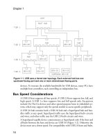
Figure 1-1. USB uses a tiered star topology. Each external hub has one
upstream-facing port and one or more downstream-facing ports.
USB Basics
17
a SuperSpeed device that doesn’t fully function at a lower speed must at least
respond to bus resets and standard requests at another speed to inform the host
that the device requires SuperSpeed to perform its function.
A non-SuperSpeed, high-speed-capable device communicates at high speed if
the host and all hubs between are USB 2.0 or higher (Figure 1-3). For compati-
bility with USB 1.x hosts and hubs, a high-speed device that doesn’t fully func-
tion at full speed must at least respond to bus resets and standard requests at full
speed to inform the host that the device requires high speed to perform its func-
tion. Many high-speed devices function, if more slowly, at full speed because
Figure 1-2. USB 3.0 hosts and hubs support all four speeds for downstream
communications.
Chapter 1
18
adding support for full speed is generally easy and is required to pass USB IF
compliance tests.
A device that supports full or low speed communicates with its nearest hub at
that speed. For any segments upstream from that hub, if all upstream hubs are
USB 2.0 or higher, the device’s traffic travels at high speed.
6GTOKPQNQI[
In the world of USB, the words function and device have specific meanings. Also
important is the concept of a USB port and how it differs from other ports such
as RS-232.
(WPEVKQP
A USB function is a set of one or more related interfaces that expose a capabil-
ity. Examples of functions are a mouse, a set of speakers, a data-acquisition unit,
or a hub. A single physical device can contain multiple functions. For example,
Figure 1-3. USB 2.0 hubs use high speed for upstream communications if the
host and all hubs between are USB 2.0 or USB 3.0.
USB Basics
19
a device might provide both a printer and a scanner function. A host identifies a
device’s functions by requesting a device descriptor and one or more interface
descriptors from the device. The descriptors are data structures that contain
information about the device.
&GXKEG
A device is a logical or physical entity that performs one or more functions.
Hubs and peripherals are devices. The host assigns a unique address to each
device on the bus. A compound device contains a hub with one or more perma-
nently attached devices. The host treats a compound device in much the same
way as if the hub and its functions were separate physical devices. The hub and
embedded devices each have a unique address. A USB 3.0 hub is a special case.
The hub contains both a USB 2.0 hub function and a USB 3.0 hub function.
A composite device has one bus address but multiple, independent interfaces
that each provide a function. Each interface can use a different driver on the
host. For example, a composite device could have interfaces for mass storage
and a keyboard.
2QTV
In general terms, a hardware computer port is an addressable location that can
connect to peripheral circuits. A port’s circuits can terminate at a cable connec-
tor or be hard-wired to peripheral circuits. For USB, each downstream-facing
connector on a hub represents a USB port. Host applications can’t access USB
ports directly but instead communicate with drivers assigned to the devices
attached to ports. A USB host controller may reside at a series of port addresses
the system’s CPU accesses, but these ports are distinct from the ports on the
bus.
&KXKUKQPQH.CDQT
The host and its devices each have defined responsibilities. The host bears most
of the burden of managing communications, but a device must have the intelli-
gence to respond to communications from the host and other events on the
bus.
Chapter 1
20
6JG*QUVŏU&WVKGU
To communicate with USB devices, a computer needs hardware and software
that support the USB host function. The hardware consists of a USB host con-
troller and a root hub with one or more USB ports. The software support is
typically an operating system that enables device drivers to communicate with
lower-level drivers that access the USB hardware.
A typical PC has one or more hardware host controllers that each support mul-
tiple ports. The host is in charge of the bus. The host has to know what devices
are on the bus and the capabilities of each device. The host must also do its best
to ensure that all devices on the bus can send and receive data as needed. A bus
may have many devices, each with different requirements, all wanting to trans-
fer data at the same time. The host’s job isn’t trivial.
Fortunately, the host-controller hardware and drivers in Windows and other
operating systems do much of the work of managing the bus. Each device
attached to the host must have an assigned device driver that enables applica-
tions to communicate with the device. System-level software components man-
age communications between the device driver and the host controller and root
hub.
Applications don’t have to know the hardware-specific details of communicat-
ing with devices. All the application has to do is send and receive data using
standard operating-system functions or other software components. Often the
application doesn’t have to know or care whether the device uses USB or
another interface.
The host performs each of the tasks described below.
&GVGEV&GXKEGU
On power-up, hubs make the host aware of all attached USB devices. In a pro-
cess called enumeration, the host determines what bus speed to use, assigns an
address, and requests additional information. After power-up, whenever a
device is removed or attached, a hub informs the host of the event, and the host
enumerates any newly attached device and removes any detached device from
its list of devices available to applications.
/CPCIG&CVC(NQY
The host manages traffic on the bus. Multiple devices may want to transfer data
at the same time. The host controller divides the available time into intervals
USB Basics
21
and gives each transmission a portion of the available time. A USB 3.0 host can
simultaneously transmit SuperSpeed data, receive SuperSpeeed data, and trans-
mit or receive data at a USB 2.0 speed. A USB 2.0 bus carries data at one speed
at a time and in one direction at a time.
During enumeration, a device’s driver requests bandwidth for transfers that
must have guaranteed timing. If the bandwidth isn’t available, the driver can
request a smaller portion of the bandwidth or wait until the requested band-
width is available. Transfers that have no guaranteed timing use the remaining
bandwidth and must wait if the bus is busy.
'TTQT%JGEMKPI
When transferring data, the host adds error-checking bits. On receiving data,
the device performs calculations on the data and compares the result with
received error-checking bits. If the results don’t match, the device doesn’t
acknowledge receiving the data and the host knows it should retransmit. In a
similar way, the host error-checks data received from devices. USB also supports
a transfer type without acknowledgments for use with data such as real-time
audio that tolerates errors to enable a constant transfer rate.
If a transmission attempt fails after multiple tries, the host can inform the
device’s driver of the problem, and the driver can notify the application so it can
take action as needed.
2TQXKFGCPF/CPCIG2QYGT
In addition to data wires, a USB cable has wires for a +5V supply and ground.
Some devices draw all of their power from the bus. The host provides power to
all devices on power up or attachment and works with the devices to conserve
power when possible. A high-power USB 2.0 device can draw up to 500 mA
from the bus. A high-power SuperSpeed device can draw up to 900 mA from a
USB 3.0 bus. Ports on some battery-powered hosts and hubs support only
low-power devices, which are limited to 100 mA (USB 2.0) or 150 mA (Super-
Speed). To conserve power when the bus is idle, a host can require devices to
enter a low-power state and reduce their use of bus current.
'ZEJCPIG&CVCYKVJ&GXKEGU
All of the above tasks support the host’s main job, which is to exchange data
with devices. In some cases, a device driver requests the host to attempt to send
Chapter 1
22
or receive data at defined intervals, while in others the host communicates only
when an application or other software component requests a transfer.
6JG&GXKEGŏU&WVKGU
In many ways, a device’s duties are a mirror image of the host’s. When the host
initiates communications, the device must respond. But devices also have duties
that are unique. The device-controller hardware typically handles many respon-
sibilities. The amount of firmware support varies with the chip architecture.
Devices must perform all of the tasks described below.
&GVGEV%QOOWPKECVKQPU&KTGEVGFVQVJG%JKR
Devices must detect communications directed to the device’s address on the
bus. The device stores received data in a buffer and returns a status code or
sends requested data from a buffer or a status code. In almost all chips, these
functions are built into the hardware and require no support in code beyond
preparing the buffers to send or receive data. The firmware doesn’t have to take
other action or make decisions until the chip has detected a communication
intended for the device’s address. SuperSpeed devices have less of a burden in
detecting communications because the host routes SuperSpeed communica-
tions only to the target device.
4GURQPFVQ5VCPFCTF4GSWGUVU
On power up or when a device attaches to a powered system, a device must
respond to standard requests sent by the host computer during enumeration.
The host may also send requests any time after enumeration completes.
All devices must respond to these requests, which query the capabilities and sta-
tus of the device or request the device to take other action. On receiving a
request, the device places data or status information in a buffer to send to the
host. For some requests, such as selecting a configuration, the device takes other
action in addition to responding to the host computer.
The USB specification defines requests, and a class or vendor may define addi-
tional requests. On receiving a request the device doesn’t support, the device
responds with a status code.
'TTQT%JGEM
Like the host, a device adds error-checking bits to the data it sends. On receiv-
ing data that includes error-checking bits, the device performs the error-check-
USB Basics
23
ing calculations. The device’s response or lack of response tells the host whether
to re-transmit. The device also detects the acknowledgement the host returns
on receiving data from the device. The device controller’s hardware typically
performs these functions.
/CPCIG2QYGT
A device may have its own power supply, obtain power from the bus, or use
power from both sources. A host can request a device to enter the low-power
Suspend state, which requires the device to draw no more than 2.5 mA of bus
current. Some devices support remote wakeup, which can request to exit the
Suspend state. USB 3.0 hosts can place individual functions within a USB 3.0
device in the Suspend state. With host support, devices can use additional, less
restrictive low-power states to conserve power and extend battery life.
'ZEJCPIG&CVCYKVJVJG*QUV
All of the above tasks support the main job of a device’s USB port, which is to
exchange data with the host. For most transfers where the host sends data to the
device, the device responds to each transfer attempt by sending a code that indi-
cates whether the device accepted the data or was too busy to accept it. For
most transfers where the device sends data to the host, the device must respond
to each attempt by returning data or a code indicating the device has no data to
send. Typically, the hardware responds according to firmware settings and the
error-checking result. Some transfers don’t use acknowledgements, and the
sender receives no feedback about whether the receiver accepted transmitted
data.
Devices send data only when the host requests data. SuperSpeed devices can
send a packet that causes the host to request data from the device.
The controller chip’s hardware handles the details of formatting the data for the
bus. The formatting includes adding error-checking bits to data to transmit,
checking for errors in received data, and sending and receiving the individual
bits on the bus.
Of course, the device must also do whatever other tasks it’s responsible for. For
example, a mouse must be ready to detect movement and button clicks, a
data-acquisition unit has to read the data from its sensors, and a printer must
translate received data into images on paper.
Chapter 1
24
$WU5RGGFUCPF&CVC6JTQWIJRWV
The data throughput, or rate of transfer of application data, between a device
and host is less than the bus speed and isn’t always predictable. Some of the
transmitted bits identify, synchronize, and error-check the data, and the
throughput also varies with the transfer type and how busy the bus is.
For time-sensitive data, USB supports transfer types that have a guaranteed rate
or guaranteed maximum latency. Isochronous transfers have a guaranteed rate,
where the host can request a specific number of bytes to transfer at defined
intervals. The intervals can be as short as 1 ms at full speed or 125
µs at high
speed and SuperSpeed. Isochronous transfers have no error correcting, however.
Interrupt transfers have error correcting and guaranteed maximum latency. The
device specifies a maximum interval, and when a driver has requested a data
transfer, the host allows no more than the specified interval, or maximum
latency, to elapse between transfer attempts. The requested maximum interval
can have a range of 10–255 ms at low speed, 1–255 ms at full speed, and 125
µs
to 4.096 s at high speed and SuperSpeed.
Because all devices share the bus, a device has no guarantee that a particular rate
or maximum latency will be available on attachment. If the bus is too busy to
allow a requested transfer rate or maximum latency, the host refuses to complete
the configuration process that enables the host to schedule transfers. The
device’s driver can then request a configuration or interface that requires less
bandwidth. To take full advantage of reserved bandwidth, the device driver and
application software and device firmware must eliminate retries as much as pos-
sible. The device should have data ready to send when the host requests it and
should be ready to accept data when the host sends it.
Of USB’s four transfer types, the fastest on an otherwise idle bus are bulk trans-
fers, with theoretical maximums of around 1.2 MB/s at full speed, 53 MB/s at
high speed, and 400 MB/s at SuperSpeed. Isochronous transfers can request the
most bandwidth (1.023 MB/s at full speed, 24.576 MB/s at high speed, and
393 MB/s at SuperSpeed). Low speed doesn’t support bulk or isochronous
transfers, and the maximum guaranteed bandwidth for a single low-speed trans-
fer is 800 bytes per second.
&GXGNQRKPIC&GXKEG
Designing a USB device for PCs involves both getting the device up and run-
ning and providing software to communicate with the device.
USB Basics
25
%QORQPGPVU
A USB device needs the following:
• A device-controller chip with a USB interface and a CPU or other intelli-
gent hardware that communicates with the controller. The CPU can be in
the same chip as the controller or in a different chip.
• Program code, hardware, or a combination of these to carry out the USB
communications in the device.
• Hardware and code to carry out the device’s function (processing data,
reading inputs, writing to outputs).
The host that communicates with the device needs the following:
• Host controller hardware and software (typically included with the operat-
ing system).
• Device-driver software on the host to enable applications to communicate
with the device. The driver may be included with the operating system or
provided by the vendor, the chip company, or another source.
• Application software to enable users to access the device. For standard
device types such as a mouse, keyboard, or disk drive, you don’t need cus-
tom application software, though you may want to write a test application.
6QQNUHQT&GXGNQRKPI
To develop a USB device, you need the following tools:
• An assembler or compiler to create the device firmware (the code that runs
inside the device’s controller chip).
• Device-programmer hardware that enables storing the assembled or com-
piled code in the controller’s program memory.
• A compiler for writing and debugging host software, which may include a
combination of a device driver, filter driver, and application code.
Also recommended are a monitor program for debugging the device firmware
and a protocol analyzer for viewing USB traffic.
5VGRUKP&GXGNQRKPIC2TQLGEV
The steps in project development include initial decisions, enumerating, and
exchanging data.