USB Complete fourth- P31 docx
Bạn đang xem bản rút gọn của tài liệu. Xem và tải ngay bản đầy đủ của tài liệu tại đây (193.62 KB, 10 trang )
277
*WOCP+PVGTHCEG&GXKEGU
7UKPI%QPVTQNCPF
+PVGTTWRV6TCPUHGTU
The human interface device (HID) class was one of the first USB classes sup-
ported under Windows. On PCs running Windows 98 or later, applications
can communicate with HIDs using the drivers built into the operating system.
Because the HID class supports exchanging data for application-specific pur-
poses, many special-purpose devices use the HID class.
Chapter 7 introduced the class. This chapter shows how to determine whether a
device can use the human-interface class, introduces HID-specific requests, and
discusses HID firmware options. Chapter 12 describes the reports that HIDs
use to exchange information and Chapter 13 shows how to access HIDs from
applications.
Chapter 11
278
9JCVKUC*+&!
The name human interface device suggests that HIDs interact directly with peo-
ple, and many HIDs do just that. A mouse detects when someone moves it or
presses a key. A host may send data that translates to an effect that a user senses
on a joystick. Besides keyboards, mice, and joysticks, devices with HID inter-
faces include remote controls; telephone keypads; game controls such as data
gloves and steering wheels; barcode readers; and UPS units. Devices with phys-
ical control panels can use a HID interface to send control-panel input to the
host. Devices with virtual control panels on the host can use a HID interface to
send control-panel data to the device. A virtual control panel can be cheaper to
implement than traditional physical controls on a device.
A HID doesn’t have to have a human interface. The device just needs to be able
to function within the limits of the HID class specification. These are the major
abilities and limits of HID-class devices:
• All data exchanged resides in fixed-length structures called reports. The
host sends and receives data by sending and requesting reports in control or
interrupt transfers. The report format is flexible and can handle just about
any type of data.
• A HID must have an interrupt IN endpoint for sending Input reports.
• A HID can have at most one interrupt IN endpoint and one interrupt
OUT endpoint. A device that requires more interrupt endpoints can be a
composite device with multiple HID interfaces. An application obtains sep-
arate handles for each HID in the device.
• The interrupt IN endpoint enables the HID to send information to the
host at unpredictable times. For example, there’s no way for the host com-
puter to know when a user will press a key on the keyboard, so the host’s
driver uses interrupt transactions to poll the device periodically to obtain
new data. SuperSpeed devices can send ERDY Transaction Packets to
request communications with the host.
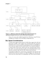
• The rate of data exchange is limited. As Chapter 3 explained, a host can
guarantee a low-speed interrupt endpoint a maximum data transfer rate of
800 bytes/sec. For full-speed endpoints, the maximum is 64 kB/s.
High-speed and SuperSpeed endpoints support faster rates, but to comply
with the USB 2.0 and USB 3.0 specifications, the endpoints in the default
interface should request no more than 64 kB/s. Under Windows, support-
ing an alternate HID interface requires a vendor-provided driver, which
Human Interface Devices: Using Control and Interrupt Transfers
279
eliminates the advantage of using Windows-provided drivers. Control
transfers have no guaranteed bandwidth except for the bandwidth reserved
for all control transfers on the bus.
• Windows 98 Gold (original edition) supports USB 1.0, so interrupt OUT
transfers aren’t supported and all host-to-device reports must use control
transfers.
A HID may be just one of multiple interfaces in a device. For example, a USB
speaker might use isochronous transfers for audio and a HID interface for con-
trolling volume, balance, treble, and bass.
*CTFYCTG4GSWKTGOGPVU
To comply with the HID specification, the interface’s endpoints and descriptors
must meet several requirements.
'PFRQKPVU
All HID transfers use either the control endpoint or an interrupt endpoint.
Every HID must have an interrupt IN endpoint for sending data to the host.
An interrupt OUT endpoint is optional. Table 11-1 shows the transfer types
and their typical use in HIDs.
4GRQTVU
The requirement for an interrupt IN endpoint suggests that every HID must
have at least one Input report defined in the HID’s report descriptor. Output
and Feature reports are optional.
%QPVTQN6TCPUHGTU
The HID specification defines six class-specific requests. Two requests, Set
Report and Get Report, provide a way for the host and device to transfer
reports to and from the device using control transfers. Set Idle and Get Idle set
and read the Idle rate, which determines whether or not a device resends data
that hasn’t changed since the last report. Set Protocol and Get Protocol set and
read a protocol value, which can enable a device to function with a simplified
protocol when the full HID drivers aren’t loaded on the host, such as during
boot up.
Chapter 11
280
+PVGTTWRV6TCPUHGTU
Interrupt endpoints provide another way to exchange data, especially when the
receiver must get the data periodically and with minimum delay. Control trans-
fers can be delayed if the bus is very busy, while the bandwidth for interrupt
transfers is guaranteed to be available after successful enumeration.
The ability to do Interrupt OUT transfers was added in USB 1.1, and the
option to use an interrupt OUT pipe was added to version 1.1 of the HID
specification. Windows 98 SE was the first Windows edition to support USB
1.1 and HID 1.1.
(KTOYCTG4GSWKTGOGPVU
The device’s descriptors must include an interface descriptor for the HID class,
a class-specific HID descriptor, and an interrupt IN endpoint descriptor. An
interrupt OUT endpoint descriptor is optional. The firmware must also con-
tain a class-specific report descriptor with information about the format and use
of the report data.
A HID can support one or more reports. The report descriptor specifies the size
and contents of the data in a device’s report(s) and may also include informa-
tion about how the receiver of the data should use the data. Values in the
descriptor define each report as an Input, Output, or Feature report. The host
receives data in Input reports and sends data in Output reports. A Feature
report can travel in either direction.
Table 11-1: The transfer type used in a HID transfer depends on the chip’s
abilities and the requirements of the data being sent.
6TCPUHGT
6[RG
5QWTEGQH
&CVC
6[RKECN&CVC 4GSWKTGF
2KRG!
9+PFQYU
5WRRQTV
Control Device
(IN transfer)
Data that doesn’t have critical timing
requirements.
yes Windows 98
Gold and later
Host
(OUT transfer)
Data that doesn’t have critical timing
requirements, or any data if there is
no OUT interrupt pipe.
Interrupt Device
(IN transfer)
Periodic or low-latency data. yes
Host
(OUT transfer)
Periodic or low-latency data. no Windows 98
SE and later
Human Interface Devices: Using Control and Interrupt Transfers
281
Every device should support at least one Input report that the host can retrieve
using interrupt transfers or control requests. Output reports are optional. To be
compatible with Windows 98 Gold, devices that use Output reports should
support sending the reports using control transfers. Using interrupt transfers for
Output reports is optional. Feature reports always use control transfers and are
optional.
&GUETKRVQTU
As with any USB device, a HID’s descriptors tell the host what it needs to know
to communicate with the device. Listing 11-1 shows example device, configura-
tion, interface, class, and endpoint descriptors for a HID with a vendor-specific
function.
The host learns about the HID interface during enumeration by sending a Get
Descriptor request for the configuration containing the HID interface. An
interface descriptor specifies the HID interface. A HID class descriptor specifies
the combined number of report and physical descriptors supported by the
interface. During enumeration, the HID driver requests the report descriptor
and any physical descriptors.
2$2
In PICBASIC PRO, descriptor tables are in assembly code. Each table is a list
of values with each preceded by a retlw instruction, which places the literal
value that follows in the working register and returns to the calling code. You
don’t have to know assembly code to compose a descriptor. Start with an exam-
ple and edit the values as needed.
Chapter 11
282
Device Descriptor
12 bLength Descriptor size in bytes
01 bDescriptorType Descriptor type (Device)
0200 bcdUSB USB Specification release number (BCD) (2.00)
00 bDeviceClass Class Code (class is specified in interface descriptor)
00 bDeviceSubClass Subclass code
00 bDeviceProtocol Protocol code
08 bMaxPacketSize0 Endpoint zero maximum packet size
0925 idVendor Vendor ID (Lakeview Research)
1234 idProduct Product ID
0100 bcdDevice Device release number (BCD)
01 iManufacturer Manufacturer string index
02 iProduct Product string index
00 iSerialNumber Device serial number string index
01 bNumConfigurations Number of configurations
Configuration Descriptor
09 bLength Descriptor size in bytes
02 bDescriptorType Descriptor type (Configuration)
0029 wTotalLength Total length of this and subordinate descriptors
01 bNumInterfaces Number of interfaces in this configuration
01 bConfigurationValue Index of this configuration
00 iConfiguration Configuration string index
A0 bmAttributes Attributes (bus powered, remote wakeup supported)
32 bMaxPower Maximum power consumption (100 mA)
Interface Descriptor
09 bLength Descriptor size in bytes
04 bDescriptorType Descriptor type (Interface)
00 bInterfaceNumber Interface Number
00 bAlternateSetting Alternate Setting Number
02 bNumEndpoints Number of endpoints in this interface
03 bInterfaceClass Interface class (HID)
00 bInterfaceSubclass Interface subclass
00 bInterfaceProtocol Interface protocol
00 iInterface Interface string index
Listing 11-1: Example descriptors for a vendor-specific HID. All values are in
hexadecimal. (Part 1 of 2)
Human Interface Devices: Using Control and Interrupt Transfers
283
HID Descriptor
09 bLength Descriptor size in bytes
21 bDescriptorType Descriptor type (HID)
0110 bcdHID HID Spec. release number (BCD) (1.1)
00 bCountryCode Country code
01 bNumDescriptors Number of subordinate class descriptors
22 bDescriptorType Descriptor type (report)
002F wDescriptorLength Report descriptor size in bytes
Interrupt IN Endpoint Descriptor
07 bLength Descriptor size in bytes
05 bDescriptorType Descriptor type (Endpoint)
81 bEndpointAddress Endpoint number and direction (1 IN)
03 bmAttributes Transfer type (interrupt)
0040 wMaxPacketSize Maximum packet size
0A bInterval polling interval (milliseconds)
Interrupt OUT Endpoint Descriptor
07 bLength Descriptor size in bytes
05 bDescriptorType Descriptor type (Endpoint)
01 bEndpointAddress Endpoint number and direction (1 OUT)
03 bmAttributes Transfer type (interrupt)
0040 wMaxPacketSize Maximum packet size
0A bInterval polling interval (milliseconds)
Listing 11-1: Example descriptors for a vendor-specific HID. All values are in
hexadecimal. (Part 2 of 2)
Chapter 11
284
Here is Listing 11-1’s device descriptor for use in PICBASIC PRO:
DeviceDescriptor
retlw (EndDeviceDescriptor-DeviceDescriptor)/2; bLength
retlw 0x01 ; bDescriptorType
retlw 0x00 ; bcdUSB low byte
retlw 0x02 ; bcdUSB high byte
retlw 0x00 ; bDeviceClass
retlw 0x00 ; bDeviceSubClass
retlw 0x00 ; bDeviceProtocol
retlw 0x08 ; bMaxPacketSize0
retlw 0x25 ; idVendor low byte
retlw 0x09 ; idVendor high byte
retlw 0x34 ; idProduct low byte
retlw 0x12 ; idProduct high byte
retlw 0x00 ; bcdDevice low byte
retlw 0x01 ; bcdDevice high byte
retlw 0x01 ; iManufacturer
retlw 0x02 ; iProduct
retlw 0x00 ; iSerialNumber
retlw 0x01 ; bNumConfigurations
EndDeviceDescriptor
%
For Microchip’s MPLAB C18 compiler, descriptors can reside in structures.
This structure holds a device descriptor:
typedef struct __attribute__ ((packed)) _USB_DEVICE_DESCRIPTOR
{
BYTE bLength;
BYTE bDescriptorType;
WORD bcdUSB;
BYTE bDeviceClass;
BYTE bDeviceSubClass;
BYTE bDeviceProtocol;
BYTE bMaxPacketSize0;
WORD idVendor;
WORD idProduct;
WORD bcdDevice;
BYTE iManufacturer;
BYTE iProduct;
BYTE iSerialNumber;
BYTE bNumConfigurations;
} USB_DEVICE_DESCRIPTOR;
Human Interface Devices: Using Control and Interrupt Transfers
285
This is Listing 11-1’s device descriptor stored in a structure:
ROM USB_DEVICE_DESCRIPTOR device_dsc=
{
0x12, // bLength
0x01, // bDescriptorType
0x0200, // bcdUSB
0x00, // bDeviceClass
0x00, // bDeviceSubClass
0x00, // bDeviceProtocol
0x08, // bMaxPacketSize0
0x0925, // idVendor
0x1234, // idProduct
0x0100, // bcdDevice
0x01, // iManufacturer
0x02, // iProduct
0x00, // iSerialNumber
0x01 // bNumConfigurations
};
6JG*+&+PVGTHCEG
In the interface descriptor, bInterfaceclass = 03h to identify the interface as a
HID. Other fields that contain HID-specific information in the interface
descriptor are the bInterfaceSubclass and bInterfaceProtocol fields, which can
specify a boot interface.
If bInterfaceSubclass = 01h, the device supports a boot interface. A HID with a
boot interface can communicate with the host even when the host hasn’t loaded
its HID drivers. This situation might occur when the computer boots directly
to DOS or when viewing the system setup screens that you can access on
bootup, or when using Windows Safe mode for system troubleshooting.
A keyboard or mouse with a boot interface can use a simplified protocol sup-
ported by the BIOS in many hosts. The BIOS loads from ROM or other
non-volatile memory on bootup and is available in any operating-system mode.
The HID specification defines boot-interface protocols for keyboards and mice.
If a device has a boot interface, bInterfaceProtocol indicates if the HID sup-
ports a keyboard (01h) or mouse (02h) function.
The HID Usage Tables document defines the report format for keyboards and
mice that use the boot protocol. The BIOS understands the boot protocol and
assumes that a boot device will support the protocol, so the BIOS doesn’t need
to read a report descriptor from the device. Before sending or requesting