rf and microwave wireless systems
Bạn đang xem bản rút gọn của tài liệu. Xem và tải ngay bản đầy đủ của tài liệu tại đây (6.19 MB, 355 trang )
RF and Microwave
Wireless Systems
RF and Microwave Wireless Systems. Kai Chang
Copyright # 2000 John Wiley & Sons, Inc.
ISBNs: 0-471-35199-7 (Hardback); 0-471-22432-4 (Electronic)
RF and Microwave
Wireless Systems
KAI CHANG
Texas A&M University
A WILEY-INTERSCIENCE PUBLICATION
JOHN WILEY & SONS, INC.
NEW YORK=CHICHESTER=WEINHEIM=BRISBANE=SINGAPORE=TORONTO
Designations used by companies to distinguish their products are often claimed as trademarks. In all
instances where John Wiley & Sons, Inc., is aware of a claim, the product names appear in initial capital or
ALL CAPITAL LETTERS. Readers, however, should contact the appropriate companies for more
complete information regarding trademarks and registration.
Copyright # 2000 by John Wiley & Sons, Inc. All rights reserved.
No part of this publication may be reproduced, stored in a retrieval system or transmitted in any form or by
any means, electronic or mechanical, including uploading, downloading, printing, decompiling, recording
or otherwise, except as permitted under Sections 107 or 108 of the 1976 United States Copyright Act,
without the prior written permission of the Publisher. Requests to the Publisher for permission should be
addressed to the Permissions Department, John Wiley & Sons, Inc., 605 Third Avenue, New York, NY
10158-0012, (212) 850-6011, fax (212) 850-6008, E-Mail: PERMREQ @ WILEY.COM.
This publication is designed to provide accurate and authoritative information in regard to the subject
matter covered. It is sold with the understanding that the publisher is not engaged in rendering professional
services. If professional advice or other expert assistance is required, the services of a competent
professional person should be sought.
ISBN 0-471-22432-4
This title is also available in print as ISBN 0-471-35199-7.
For more information about Wiley products, visit our web site at www.Wiley.com.
To my parents and my family
Contents
Preface xi
Acronyms xiii
1 Introduction 1
1.1 Brief History of RF and Microwave Wireless Systems 1
1.2 Frequency Spectrums 3
1.3 Wireless Applications 6
1.4 A Simple System Example 7
1.5 Organization of This Book 8
2 Review of Waves and Transmission Lines 10
2.1 Introduction 10
2.2 Wave Propagation 12
2.3 Transmission Line Equation 17
2.4 Reflection, Transmission, and Impedance for a Terminated
Transmission Line 20
2.5 Voltage Standing-Wave Ratio 22
2.6 Decibels, Insertion Loss, and Return Loss 27
2.7 Smith Charts 33
2.8 S-Parameters 39
2.9 Coaxial Lines 41
2.10 Microscript Lines 43
2.11 Waveguides 50
2.12 Lumped Elements 54
2.13 Impedance Matching Networks 55
Problems 63
References 65
vii
3 Antenna Systems 67
3.1 Introduction 67
3.2 Isotropic Radiator and Plane Waves 69
3.3 Far-Field Region 71
3.4 Antenna Analysis 73
3.5 Antenna Characteristics and Parameters 74
3.6 Monopole and Dipole Antennas 80
3.7 Horn Antennas 86
3.8 Parabolic Dish Antennas 88
3.9 Microstrip Patch Antennas 90
3.10 Antenna Arrays and Phased Arrays 98
3.11 Antenna Measurements 104
Problems 104
References 109
4 Various Components and Their System Parameters 111
4.1 Introduction and History 111
4.2 Couplers, Hybrids, and Power Dividers=Combiners 114
4.3 Resonators, Filters, and Multiplexers 118
4.4 Isolators and Circulators 128
4.5 Detectors and Mixers 130
4.6 Switches, Phase Shifters, and Attenuators 134
4.7 Oscillators and Amplifiers 139
4.8 Frequency Multipliers and Dividers 143
Problems 145
References 148
5 Receiver System Parameters 149
5.1 Typical Receivers 149
5.2 System Considerations 150
5.3 Natural Sources of Receiver Noise 152
5.4 Receiver Noise Figure and Equivalent Noise Temperature 154
5.5 Compression Points, Minimum Detectable Signal,
and Dynamic Range 158
5.6 Third-Order Intercept Point and Intermodulation 161
5.7 Spurious Responses 166
5.8 Spurious-Free Dynamic Range 166
Problems 168
References 171
6 Transmitter and Oscillator Systems 172
6.1 Transmitter Parameters 172
6.2 Transmitter Noise 173
viii CONTENTS
6.3 Frequency Stability and Spurious Signals 176
6.4 Frequency Tuning, Output Power, and Efficiency 177
6.5 Intermodulation 180
6.6 Crystal Reference Oscillators 184
6.7 Phase-Locked Oscillators 186
6.8 Frequency Synthesizers 188
Problems 191
References 194
7 Radar and Sensor Systems 196
7.1 Introduction and Classifications 196
7.2 Radar Equation 198
7.3 Radar Equation Including Pulse Integration and System Losses 202
7.4 Radar Cross Section 205
7.5 Pulse Radar 209
7.6 Continuous-Wave or Doppler Radar 212
7.7 Frequency-Modulated Continuous-Wave Radar 216
7.8 Direction Finding and Tracking 222
7.9 Moving-Target Indication and Pulse Doppler Radar 228
7.10 Synthetic Aperture Radar 232
7.11 Practical Radar Examples 233
Problems 236
References 242
8 Wireless Communication Systems 243
8.1 Introduction 243
8.2 Friis Transmission Equation 244
8.3 Space Loss 247
8.4 Link Equation and Link Budget 248
8.5 Effective Isotropic Radiated Power and G=T Parameters 252
8.6 Radio=Microwave Links 254
8.7 Satellite Communication Systems 255
8.8 Mobile Communication Systems and Wireless Cellular Phones 258
8.9 Personal Communication Systems and Satellite Personal
Communication Systems 262
Problems 270
References 273
9 Modulation and Demodulation 274
9.1 Introduction 274
9.2 Amplitude Modulation and Demodulation 275
9.3 Frequency Modulation 279
9.4 Digital Shift-Keying Modulation 280
CONTENTS ix
9.5 Bit Error Rate and Bandwidth Efficiency 286
9.6 Sampling and Pulse Code Modulation 289
Problems 292
References 293
10 Multiple-Access Techniques 294
10.1 Introduction 294
10.2 Frequency Division Multiple Access and Frequency Division
Multiplexing 294
10.3 Time Division Multiple Access and Time Division Multiplexing 295
10.4 Spread Spectrum and Code Division Multiple Access 298
References 303
11 Other Wireless Systems 304
11.1 Radio Navigation and Global Positioning Systems 304
11.2 Motor Vehicle and Highway Applications 309
11.3 Direct Broadcast Satellite Systems 313
11.4 RF Identification Systems 313
11.5 Remote Sensing Systems and Radiometers 317
11.6 Surveillance and Electronic Warfare Systems 320
Problems 328
References 330
Index 333
x CONTENTS
Preface
Wireless personal mobile and cellular communications are expected to be one of the
hottest growth areas of the 2000s and beyond. They have enjoyed the fastest growth
rate in the telecommunications industry—adding customers at a rate of 20–30% a
year. Presently, at least six satellite systems are being developed so that wireless
personal voice and data communications can be transmitted from any part of the
earth to another using a simple, hand-held device. These future systems will provide
data and voice communications to anywhere in the world, using a combination of
wireless telephones, wireless modems, terrestrial cellular telephones and satellites.
The use of wireless remote sensing, remote identification, direct broadcast, global
navigation, and compact sensors has also gained popularity in the past decade.
Wireless communications and sensors have become a part of a consumer’s daily life.
All of these wireless systems consist of a radio frequency (RF) or microwave front
end.
Although many new wireless courses have been offered at universities and in
industry, there is yet to be a textbook written on RF and microwave wireless systems.
The purpose of this book is to introduce students and beginners to the general
hardware components, system parameters, and architectures of RF and microwave
wireless systems. Practical examples of components and system configurations are
emphasized. Both communication and radar=sensor systems are covered. Many
other systems, such as, the global positioning system (GPS), RF identification
(RFID), direct broadcast system (DBS), surveillance, smart highways, and smart
automobiles are introduced. It is hoped that this book will bridge the gap between
RF=microwave engineers and communication system engineers.
The materials covered in this book have been taught successfully at Texas A&M
University to a senior class for the past few years. Half of the students are from RF
and microwave areas, and half are from communications, signal processing, solid-
state, optics, or other areas. The book is intended to be taught for one semester to an
undergraduate senior class or first-year graduate class with some sections assigned to
xi
students for self-study. The end-of-chapter problems will strengthen the reader’s
knowledge of the subject. The reference sections list the principal references for
further reading.
Although this book was written as a textbook, it can also be used as a reference
book for practical engineers and technicians. Throughout the book, the emphasis is
on the basic operating principles. Many practical examples and design information
have been included.
I would like to thank all of my former students who used my notes in class for
their useful comments and suggestions. I would also like to thank Mingyi Li, Paola
Zepeda, Chris Rodenbeck, Matt Coutant and James McSpadden for critical review of
the manuscript. Michelle Rubin has done an excellent job in editing and preparing
the manuscript. Taehan Bae has helped to prepared some of the art work. Finally, I
wish to express my deep appreciation to my wife, Suh-jan, and my children, Peter
and Nancy, for their patience and support.
K
AI CHANG
February 2000
xii PREFACE
Acronyms
AF array factor
AGC automatic gain control
AM amplitude modulated
AMPS advanced mobile phone service
APTS advanced public transit systems
ASK amplitude shift keying
ATIS advanced traveler information system
ATMS advanced traffic management system
AUT antenna under test
AVCS advanced vehicle control system
AVI automatic vehicle identification
BER bit error rate
BPF bandpass filter
BPSK biphase shift keying
BSF bandstop filter
BW bandwidth
CAD computer-aided design
CDMA code division multiple access
CEP circular probable error
CMOS complementary MOS
CP circularly polarized
CPL cross-polarization level
CRTs cathode ray tubes
CT1/2 cordless telephone 1/2
CTO cordless telephone O
CVO commercial vehicle operations
CVR crystal video receiver
CW continuous wave
xiii
DBS direct broadcast satellite
DC direct current
DECT digital european cordless telephone
DR dynamic range
DRO dielectric resonator oscillator
DSB double side band
DSSS direct-sequence spread spectrum
ECCMs electronic courter- countermeasures
ECMs electronic countermeasures
EIRP effective isotropic radiated power
EM electromagnetic
ESM electronic support measure
EW electronic warfare
FCC Federal Communications Commission
FDD frequency division duplex
FDM frequency division multiplexing
FDMA frequency division multiple access
FETs field-effect transistors
FFHSS fast frequency- hopping spread spectrum
FHSS frequency-hopping spread spectrum
FLAR forward-looking automotive radar
FMCW frequency-modulated continous wave
FM frequency modulated
FNBW first-null beamwidth
FSK frequency shift keying
GEO geosynchronous orbit
GMSK Gaussian minimum shift keying
GPS global positioning system
GSM global system for mobile communication
G=T receiver antenna gain to system noise temperature ratio
HBTs heterojunction bipolar transistors
HEMTs high-electron-mobility transistors
HPA high-power amplifier
HPBW half-power beamwidth
HPF high-pass filter
IF intermediate frequency
IFM instantaneous frequency measurement
IL insertion loss
IMD intermodulation distortion
IM intermodulation
IMPATT impact ionization avalanche transit time device
IM3 third-order intermodulation
IP3 third-order intercept point
I/Q in-phase/quadrature-phase
IVHS intelligent vehicle and highway system
xiv ACRONYMS
JCT Japanese cordless telephone
J/S jammer-to-signal
LAN local area network
LMDS local multipoint distribution service
LEO low earth orbit
LNA low-noise amplifier
LO local oscillator
LOS line-of-sight
LPF low-pass filter
LP linearly polarized
MDS minimum detectable signal
MEO medium-altitude orbit
MESFETs metal–semiconductor field-effect transistors
MIC microwave integrated circuit
MLS microwave landing system
MMIC monolithic microwave integrated circuits
MSK minimum shift keying
MTI moving target indicator
NMT Nordic mobile telephone
OQPSK offset-keyed quadriphase shift keying
PAMELA pricing and monitoring electronically of automobiles
PA power amplifier
PAE power added efficiency
PCM pulse code modulation
PCN personal communication networks
PCS personal communication systems
PDC personal digital cellular
PHS personal handy phone system
PLL phase-locked loops
PLO phase-locked oscillators
PM phase modulation
PN pseudonoise
PRF pulse repetition frequency
PSK phase shift keying
8-PSK 8-phase shift keying
16-PSK 16-phase shift keying
QAM quadrature amplitude modulation
QPSK quadriphase shift keying
RCS radar cross section
RF radio frequency
RFID radio frequency identification
RL return loss
SAR synthetic aperture radar
SAW surface acoustic wave
SEP spherical probable error
ACRONYMS xv
SFDR spurious-free dynamic range
SFHSS slow frequency- hopping spread spectrum
SLL sidelobe levels
SMILER short range microwave links for european roads
SNR signal-noise ratio
SOJ stand-off jammer
SPDT single pole, double throw
SPST single pole, single throw
SP3T single pole, triple throw
SQPSK staggered quadriphase shift keying
SS spread spectrum
SS-CDMA spread spectrum code division multiple access
SSJ self-screening jammer
SSMI special sensor microwave imager
STC sensitivity time control
TACS total access communication system
TDM time division multiplexing
TDMA time division multiple access
TE transverse electric
TEM transverse electromagnetic
TM transverse magnetic
TOI third-order intercept point
T/R transmit/receive
TWTs traveling-wave tubes
UHF ultrahigh frequencies
VCO voltage-controlled oscillator
VHF very high frequency
VLF very low frequency
VSWR voltage standing-wave ratio
WLANs wireless local-area networks
xvi ACRONYMS
RF and Microwave
Wireless Systems
Introduction
1.1 BRIEF HISTORY OF RF AND MICROWAVE WIRELESS SYSTEMS
The wireless era was started by two European scientists, James Clerk Maxwell and
Heinrich Rudolf Hertz. In 1864, Maxwell presented Maxwell's equations by
unifying the works of Lorentz, Faraday, Ampere, and Gauss. He predicted the
propagation of electromagnetic waves in free space at the speed of light. He
postulated that light was an electromagnetic phenomenon of a particular wavelength
and predicted that radiation would occur at other wavelengths as well. His theory
was not well accepted until 20 years later, after Hertz validated the electromagnetic
wave (wireless) propagation. Hertz demonstrated radio frequency (RF) generation,
propagation, and reception in the laboratory. His radio system experiment consisted
of an end-loaded dipole transmitter and a resonant square-loop antenna receiver
operating at a wavelength of 4 m. For this work, Hertz is known as the father of
radio, and frequency is described in units of hertz (Hz).
Hertz's work remained a laboratory curiosity for almost two decades, until a
young Italian, Guglielmo Marconi, envisioned a method for transmitting and
receiving information. Marconi commercialized the use of electromagnetic wave
propagation for wireless communications and allowed the transfer of information
from one continent to another without a physical connection. The telegraph became
the means of fast communications. Distress signals from the S.S. Titanic made a
great impression on the public regarding the usefulness of wireless communications.
Marconi's wireless communications using the telegraph meant that a ship was no
longer isolated in the open seas and could have continuous contact to report its
positions. Marconi's efforts earned him the Nobel Prize in 1909.
In the early 1900s, most wireless transmission occurred at very long wavelengths.
Transmitters consisted of Alexanderson alternators, Poulsen arcs, and spark gaps.
Receivers used coherers, Fleming valves, and DeForest audions. With the advent of
DeForest's triode vacuum tube in 1907, continuous waves (CW) replaced spark gaps,
1
RF and Microwave Wireless Systems. Kai Chang
Copyright # 2000 John Wiley & Sons, Inc.
ISBNs: 0-471-35199-7 (Hardback); 0-471-22432-4 (Electronic)
and more reliable frequency and power output were obtained for radio broadcasting
at frequencies below 1.5 MHz. In the 1920s, the one-way broadcast was made to
police cars in Detroit. Then the use of radio waves for wireless broadcasting,
communications between mobile and land stations, public safety systems, maritime
mobile services, and land transportation systems was drastically increased. During
World War II, radio communications became indispensable for military use in
battle®elds and troop maneuvering.
World War II also created an urgent need for radar (standing for radio detection
and ranging). The acronym radar has since become a common term describing the
use of re¯ections from objects to detect and determine the distance to and relative
speed of a target. A radar's resolution (i.e., the minimum object size that can be
detected) is proportional to wavelength. Therefore, shorter wavelengths or higher
frequencies (i.e., microwave frequencies and above) are required to detect smaller
objects such as ®ghter aircraft.
Wireless communications using telegraphs, broadcasting, telephones, and point-
to-point radio links were available before World War II. The widespread use of these
communication methods was accelerated during and after the war. For long-distance
wireless communications, relay systems or tropospheric scattering were used. In
1959, J. R. Pierce and R. Kompfner envisioned transoceanic communications by
satellites. This opened an era of global communications using satellites. The satellite
uses a broadband high-frequency system that can simultaneously support thousands
of telephone users, tens or hundreds of TV channels, and many data links. The
operating frequencies are in the gigahertz range. After 1980, cordless phones and
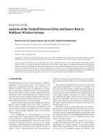
FIGURE 1.1 Summary of the history of wireless systems.
2
INTRODUCTION
cellular phones became popular and have enjoyed very rapid growth in the past two
decades. Today, personal communication systems (PCSs) operating at higher
frequencies with wider bandwidths are emerging with a combination of various
services such as voice mail, email, video, messaging, data, and computer on-line
services. The direct link between satellites and personal communication systems can
provide voice, video, or data communications anywhere in the world, even in the
most remote regions of the globe.
In addition to communication and radar applications, wireless technologies have
many other applications. In the 1990s, the use of wireless RF and microwave
technologies for motor vehicle and highway applications has increased, especially in
Europe and Japan. The direct broadcast satellite (DBS) systems have offered an
alternative to cable television, and the end of the Cold War has made many military
technologies available to civilian applications. The global positioning systems
(GPSs), RF identi®cation (RFID) systems, and remote sensing and surveillance
systems have also found many commercial applications.
Figure 1.1 summarizes the history of these wireless systems.
1.2 FREQUENCY SPECTRUMS
Radio frequencies, microwaves, and millimeter waves occupy the region of the
electromagnetic spectrum below 300 GHz. The microwave frequency spectrum is
from 300 MHz to 30 GHz with a corresponding wavelength from 100 cm to 1 cm.
Below the microwave spectrum is the RF spectrum and above is the millimeter-wave
spectrum. Above the millimeter-wave spectrum are submillimeter-wave, infrared,
and optical spectrums. Millimeter waves (30±300 GHz), which derive their name
from the dimensions of the wavelengths (from 10 to 1 mm), can be classi®ed as
microwaves since millimeter-wave technology is quite similar to that of microwaves.
Figure 1.2 shows the electromagnetic spectrum. For convenience, microwave and
millimeter-wave spectrums are further divided into many frequency bands. Figure
1.2 shows some microwave bands, and Table 1.1 shows some millimeter-wave
bands. The RF spectrum is not well de®ned. One can consider the frequency
spectrum below 300 MHz as the RF spectrum. But frequently, literatures use the RF
term up to 2 GHz or even higher.
The Federal Communications Commission (FCC) allocates frequency ranges and
speci®cations for different applications in the United States, including televisions,
radios, satellite communications, cellular phones, police radar, burglar alarms, and
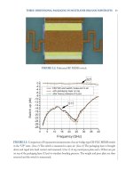
navigation beacons. The performance of each application is strongly affected by the
atmospheric absorption. The absorption curves are shown in Fig. 1.3. For example, a
secure local area network would be ideal at 60 GHz due to the high attenuation
caused by the O
2
resonance.
As more applications spring up, overcrowding and interference at lower
frequency bands pushes applications toward higher operating frequencies. Higher
frequency operation has several advantages, including:
1.2 FREQUENCY SPECTRUMS 3
FIGURE 1.2 Electromagnetic spectrum.
4
INTRODUCTION
1. Larger instantaneous bandwidth for greater transfer of information
2. Higher resolution for radar, bigger doppler shift for CW radar, and more
detailed imaging and sensing
3. Reduced dimensions for antennas and other components
4. Less interference from nearby applications
5. Fast speed for digital system signal processing and data transmission
6. Less crowded spectrum
7. Dif®culty in jamming (military applications)
TABLE 1.1 Millimeter-Wave Band Designation
Frequency Range
Designation (GHz)
Q-band 33±50
U-band 40±60
V -band 50±75
E-band 60±90
W -band 75±110
D-band 110±170
G-band 140±220
Y -band 220±325
FIGURE 1.3 Absorption by the atmosphere in clear weather.
1.2 FREQUENCY SPECTRUMS 5
The use of higher frequency also has some disadvantages:
1. More expensive components
2. Higher atmospheric losses
3. Reliance on GaAs instead of Si technology
4. Higher component losses and lower output power from active devices
5. Less accurate design tools and less mature technologies
The electron mobility in GaAs is higher than that in silicon. Therefore, GaAs
devices can operate at higher frequencies and speeds. Current silicon-based devices
are commonly used up to 2 GHz. Above 4 GHz, GaAs devices are preferred for
better performance. However, GaAs processing is more expensive, and the yield is
lower than that of silicon.
1.3 WIRELESS APPLICATIONS
Two of the most historically important RF=microwave applications are communica-
tion systems and radar; but there are many others. Currently, the market is driven by
the phenomenal growth of PCSs, although there is also an increased demand for
satellite-based video, telephone, and data communication systems.
Radio waves and microwaves play an important role in modern life. Television
signals are transmitted around the globe by satellites using microwaves. Airliners are
guided from takeoff to landing by microwave radar and navigation systems.
Telephone and data signals are transmitted using microwave relays. The military
uses microwaves for surveillance, navigation, guidance and control, communica-
tions, and identi®cation in their tanks, ships, and planes. Cellular telephones are
everywhere.
The RF and microwave wireless technologies have many commercial and military
applications. The major application areas include communications, radar, navigation,
remote sensing, RF identi®cation, broadcasting, automobiles and highways, sensors,
surveillance, medical, and astronomy and space exploration. The details of these
applications are listed below:
1. Wireless Communications. Space, long-distance, cordless phones, cellular
telephones, mobile, PCSs, local-area networks (LANs), aircraft, marine,
citizen's band (CB) radio, vehicle, satellite, global, etc.
2. Radar. Airborne, marine, vehicle, collision avoidance, weather, imaging,
air defense, traf®c control, police, intrusion detection, weapon guidance,
surveillance, etc.
3. Navigation. Microwave landing system (MLS), GPS, beacon, terrain
avoidance, imaging radar, collision avoidance, auto-pilot, aircraft, marine,
vehicle, etc.
6 INTRODUCTION
4. Remote Sensing. Earth monitoring, meteorology, pollution monitoring,
forest, soil moisture, vegetation, agriculture, ®sheries, mining, water,
desert, ocean, land surface, clouds, precipitation, wind, ¯ood, snow, iceberg,
urban growth, aviation and marine traf®c, surveillance, etc.
5. RF Identi®cation. Security, antitheft, access control, product tracking,
inventory control, keyless entry, animal tracking, toll collection, automatic
checkout, asset management, etc.
6. Broadcasting. Amplitude- and frequency-modulated (AM, FM) radio, TV,
DBS, universal radio system, etc.
7. Automobiles and Highways. Collision warning and avoidance, GPS, blind-
spot radar, adaptive cruise control, autonavigation, road-to-vehicle commu-
nications, automobile communications, near-obstacle detection, radar speed
sensors, vehicle RF identi®cation, intelligent vehicle and highway system
(IVHS), automated highway, automatic toll collection, traf®c control, ground
penetration radar, structure inspection, road guidance, range and speed
detection, vehicle detection, etc.
8. Sensors. Moisture sensors, temperature sensors, robotics, buried-object
detection, traf®c monitoring, antitheft, intruder detection, industrial sensors,
etc.
9. Surveillance and Electronic Warfare. Spy satellites, signal or radiation
monitoring, troop movement, jamming, antijamming, police radar detectors,
intruder detection, etc.
10. Medical. Magnetic resonance imaging, microwave imaging, patient monitor-
ing, etc.
11. Radio Astronomy and Space Exploration. Radio telescopes, deep-space
probes, space monitoring, etc.
12. Wireless Power Transmission. Space to space, space to ground, ground to
space, ground to ground power transmission.
1.4 A SIMPLE SYSTEM EXAMPLE
A wireless system is composed of active and passive devices interconnected to
perform a useful function. A simple example of a wireless radio system is shown in
Fig. 1.4.
The transmitter operates as follows. The input baseband signal, which could be
voice, video, or data, is assumed to be bandlimited to a frequency f
m
. This signal is
®ltered to remove any components that may be beyond the channel's passband. The
message signal is then mixed with a local oscillator (LO) signal to produce a
modulated carrier in a process called up-conversion since it produces signals at
frequencies f
LO
f
m
or f
LO
À f
m
which are normally much higher than f
m
. The
modulated carrier can then be ampli®ed and transmitted by the antenna.
When the signal arrives at the receiver, it is normally ampli®ed by a low-noise
ampli®er (LNA). The LNA may be omitted from some systems when the received
signal has enough power to be mixed directly, as may occur in short-distance
1.4 A SIMPLE SYSTEM EXAMPLE 7
communication links. The mixer then produces a signal at a frequency f
IF
f
m
or
f
IF
À f
m
in a process called down-conversion since f
IF
is chosen to be much lower
than f
LO
. The signal is ®ltered to remove any undesired harmonic and spurious
products resulting from the mixing process and is ampli®ed by an intermediate-
frequency (IF) ampli®er. The output of the ampli®er goes to a detector stage where
the baseband signal f
m
, which contains the original message, is recovered.
To perform all of these functions, the microwave system relies on separate
components that contribute speci®c functions to the overall system performance.
Broadly speaking, microwave components can be classi®ed as transmission lines,
couplers, ®lters, resonators, signal control components, ampli®ers, oscillators,
mixers, detectors, and antennas.
1.5 ORGANIZATION OF THIS BOOK
This book is organized into 11 chapters. Chapter 2 reviews some fundamental
principles of transmission lines and electromagnetic waves. Chapter 3 gives a brief
overview of how antennas and antenna arrays work. Chapter 4 provides a discussion
FIGURE 1.4 Block diagram of a simpli®ed wireless radio system.
8
INTRODUCTION