CompTIA Network+ Certification Study Guide part 4 pptx
Bạn đang xem bản rút gọn của tài liệu. Xem và tải ngay bản đầy đủ của tài liệu tại đây (150.54 KB, 10 trang )
CHAPTER 1: Network Fundamentals 16
can save their work to a dedicated server in a central location. This would
keep everyone’s files on one or more servers, allowing their work to be kept
secure and regularly backed up.
Decentralized (Distributed)
When a decentralized network model is used, a network’s resources are
distributed through different areas of the network, and administration is
shared by designating responsibility to system administrators or individual
users. For example, printers may be scattered throughout an organization,
with managers of each office being responsible for assigning permissions to
user accounts to use specific printers. By sharing administrative burdens in
this way, certain resources can now be managed by other members of the
organization.
A decentralized network model has a variety of servers, equipment, and
other resources distributed across the geographical area making up the net-
work. Although a network administrator may be able to access them over
the computer network, such network components aren’t readily accessible
physically. As such, a network administrator must rely on people who are
designated as system administrators in those locations. These people must
be properly trained on the system and responsible enough to take matters
like security seriously. If not, something as simple as changing a backup tape
could be problematic or even disastrous.
Even if an organization initially decides on having a centralized network,
decentralizing the network may be the only viable option if cost factors or
other issues come into play. For example, if a company had a slow network
connection between buildings, users might find logging into the network,
saving data to a server, or accessing network resources slow. One solution
would be to put a server in each building, so computers would be able to be
authenticated and quickly access data on the server that’s closest to them. By
distributing servers in this instance, network performance would improve,
because users wouldn’t have to authenticate or necessarily use the slow con-
nection to the other server.
Once your network model has been selected, you can then deploy your
client systems, servers, and resources accordingly. There are multiple logical
topologies you will need to select from such as peer-to-peer, client/server,
VPNs, and VLANs.
Peer-to-Peer
Years ago, most computers on a network weren’t very powerful. Hard disks,
memory, printers, and other components making up a computer system
were expensive, creating a need for dedicated servers that other computers
Logical Networking Topologies 17
accessed to store data and access necessary resources. These dedicated
servers could be mainframes or high-end computers with additional memory,
storage space, and processing power. As technology progressed, computer
workstations came to be as powerful (or in many cases more powerful) than
the servers of years past, making peer-to-peer networks a viable solution for
smaller networks.
In a peer-to-peer network, computers on the network act as equals, with
each workstation providing access to resources and data. This is a simple
type of network, where computers are able to communicate with one another,
and share what is on or attached to their computer with other users. It is also
one of the easiest types of architectures to create.
Individual users have responsibility over who can access data and
resources on their computer. OSes such as Windows XP and Windows Vista
allow accounts to be set up that will be used when other users connect to
their computer. Accounts, passwords, and permissions are saved in a local
HEAD OF THE CLASS…
Centralized Access Control
Even when servers and resources are distributed
throughout a network, it does not mean that access
control can’t be centralized. Centralized access control
is when users achieve access to the network through
a central point of authentication. Users log onto the
network through some form of authentication, such as
a username and password, which is passed to a server
that processes their request for access. The server
compares this information to a corresponding account
that’s stored in a database, and determines whether
the user has correctly identified himself or herself, and
what this person is authorized to access. The server
sends back data that authorizes the user, allowing
them to use specific resources on the network.
Because users acquire access to resources through
one source, it saves them from having to log onto each
server. Early versions of network OSes required users to
determine which server they wanted to use, and then
enter the username and password for their account on
that server. Using centralized access control, the users
only need to be authenticated once to be able to access
resources on any server they are given permissions
and rights to use.
Another benefit of centralizing access control is
that administration of accounts can be done for an
entire network through one control system. For exam-
ple, on networks using Windows 2000 Server or 2003
Server, user accounts and information are stored in
Active Directory, while Novell NetWare networks use
Novell Directory Services (NDS) or eDirectory. Using
ConsoleOne in NetWare or the Microsoft Management
Console (MMC) in Windows, a network administrator
has the ability to connect to the directory containing
user information, and control which folders a user can
access, password requirements, when the user can log
onto the network, and numerous other conditions and
controls. Rather than making changes to each server,
the administrator only needs to make changes to an
account one to affect a user’s access throughout the
network. Because of this, centralized access control is
often used in enterprises, where there are large num-
bers of computers and user accounts that need to be
managed.
CHAPTER 1: Network Fundamentals 18
database, which is used to determine what someone can do when connecting
to the computer. For example, one account may allow a user to send print
jobs to your printer, while another account may allow the user to access files
in certain directories but not print.
Because peer-to-peer networks are generally small, creating one can
be as simple as installing network adapters into each computer, attach-
ing a network cable to the adapter, and connecting the other end to
a hub or switch. If a wireless network is being created, then even the
cables aren’t necessary, as wireless adapters and a wireless router are all
that’s needed. Once this is done, each computer is configured to use the
network adapter that’s installed, and a protocol is configured to allow
communication between the computers. In cases where OSes such as
Windows XP or Vista are used, this configuration can be done through a
wizard program, which takes you step by step through the configuration
process.
One important issue with peer-to-peer networks is security. Each
computer on this type of network may allow or deny access to other com-
puters, as access to data and resources are controlled on each machine.
For example, a user could share a folder on his or her computer, allowing
other users to access the files in that folder. Because users can have the
ability to control access to files and resources on their computers, net-
work administration isn’t controlled by one person. However, problems
may exist where users grant access to data and resources based on friend-
ship with another person instead of a person’s need to perform their job.
As such, peer-to-peer networks are generally used in situations where
security isn’t a major concern, as in the case of some home networks or
small businesses.
Client/Server
In looking at the peer-to-peer network model, when one computer requests
data or other services from another computer, it acts as a client, while the
other computer delivering that data or service acts as a server. These roles
seem obscured because both computers act in either of these roles. In the
Client/Server model, these roles are clearer because it involves dedicated
servers that provide services and data to clients, without making similar
requests of them.
The Client/Server model consists of high-end computers serving clients
on a network, by providing them with specific services upon request. Years
ago, each server generally performed a single role, such as:
Logical Networking Topologies 19
File server, which allow clients to save data to folders on its hard
drive.
Print server, which redirect print jobs from clients to specific printers.
Application server, which allow clients to run certain programs
on the server, and enables multiple users to access common
applications across the network.
Database server, which allow authorized clients to view, modify,
and/or delete data in a common database.
Today, computers are more powerful and network OSes are more effec-
tive, so each server may act in several different roles. For example, a server
may be a web server for the local intranet, but also allow users to access a
database and store files in an area of its hard drive. The services provided by
the server will vary greatly depending on how it’s been configured and what’s
been installed.
The software that’s installed largely dictates the roles a dedicated
server can perform. First and foremost, the server needs to have a net-
work OS such as Windows Server 2003, Windows Server 2008, or Linux
installed on it. These server OSes provide features specifically for ser-
vicing clients, and can respond more efficiently to a greater number of
client requests than standard OSes such as Windows XP or Windows
Vista.
Once a high-end computer has server software installed, the services
provided by it need to be configured and other programs may need to be
installed. Many of the server’s functions are dependent on the server soft-
ware installed on it. For example, a server that acts as a SQL Server is a data-
base server, but needs to have a program like Microsoft SQL Server installed
on it. In the same way, a Web server on a Windows Server 2003 server would
need Internet Information Services (IIS) configured. By installing server soft-
ware on the dedicated server, you define the role that server will play on your
network.
Although a dedicated server may play a variety of roles, you should
determine whether the load placed on the server is too great, causing per-
formance to decrease. Some services provided by a server may be accessed
frequently, creating a larger workload for the server. Rather than creating
a burden for the server, the server will be dedicated to performing a sin-
gle role, or at least a decreased number of roles. For example, an e-mail
server may be accessed frequently by users of the network who want to
check for messages. Because it is used so often, many organizations will
CHAPTER 1: Network Fundamentals 20
have one server performing only this role to avoid it from being bogged
down and have users finding it slow to access their e-mail. In the same
way, if the service is essential to a business, such as Web server being
necessary for a business that sells products on the Internet, that server
will be dedicated to only that role. The more a server is dedicated to a
specific or limited number of functions, the better its performance and
the less chance there will be of everything becoming unavailable if one
server fails.
At the beginning of this chapter, we explained that a network exists when
two or more computers are connected together so they can share various
resources. Although this defines the basic nature of a network, it doesn’t
provide an understanding of the different sizes and shapes a network can
take as it’s designed and developed. Having this understanding is important
in determining the scope and physical layout of computers, cables, and other
network components. It is also vital when considering the type of media that
will be used, and whether additional components are necessary to expand
your network.
Virtual Private Network
A VPN provides users with a secure method of connectivity through a public
internetwork such as the Internet. Most companies use dedicated connec-
tions to connect to remote sites, but when users want to send private data
over the Internet they should provide additional security by encrypting the
data using a VPN.
DAMAGE AND DEFENSE
Only Use Servers as Servers
Although dedicated servers are designed to serve
clients, many of the server OSes have the ability to be
used as if they were clients. For example, Windows
servers have always had the same GUI as other
versions of Windows for standalone computers or
network workstations. This means you could install
and use Microsoft Office, games, or any number of
other software products. However, it is unwise to use
a server as if it were any other client machine on your
network.
Every time you run software on a computer, memory,
processing, and other resources are used, which could
otherwise be used for responding to client requests, and
you run the risk of crashing the server. Think of the num-
ber of times a program has locked up your computer, and
then think of the implications of what would happen if
hundreds of users had been accessing it as a server and
were now unable to do their work. The reason you have a
server is for it to act as a server. Unless you are perform-
ing work on the server related to how it functions as a
server, it is not advisable to use it for other purposes.
Logical Networking Topologies 21
What is a VPN?
When a VPN is implemented properly, it provides improved wide area
security, reduces costs associated with traditional WANs, improves produc-
tivity, and improves support for users who telecommute. Cost savings are
twofold. First, companies save money using public networks (such as the
Internet) instead of paying for dedicated circuits (such as point-to-point T1
circuits) between remote offices. Second, telecommuters do not have to pay
long-distance fees to connect to Remote Access Servers (RAS). They can sim-
ply dial into their local ISPs and create a virtual tunnel to the office. A tunnel
is created by wrapping (or encapsulating) a data packet inside another data
packet and transmitting it over a public medium. Tunneling requires three
different protocols:
Carrier Protocol The protocol used by the network (IP on the Inter-
net) that the information is traveling over.
Encapsulating Protocol The protocol, such as Point-to-Point Tun-
neling Protocol (PPTP), Layer 2 Tunneling Protocol (L2TP), IPSec,
or Secure Shell (SSH), that is wrapped around the original data.
Passenger Protocol The original data being carried.
Essentially, there are two different types of VPNs: site-to-site and remote
access.
Site-to-Site VPN
Site-to-site VPNs are normally established between corporate offices that are
separated by a physical distance extending further than normal LAN media
covers. VPNs are available as software (such as Windows VPN, available on
Windows 2003 and 2008) and hardware (firewalls such as Cisco PIX or ASA
and Nokia/Checkpoint) implementations. In general, software implementa-
tions are easier to maintain. However, hardware implementations are con-
sidered more secure, because they are not impacted by OS vulnerabilities.
For example, suppose that Company XYZ has offices in Boston and Phoenix.
As shown in Figure 1.1, both offices connect to the Internet via a T1 con-
nection. They have implemented VPN-capable firewalls in both offices and
established an encryption tunnel between them.
The first step in creating a site-to-site VPN is selecting the security pro-
tocols to be used. Common protocols associated with VPN transmission
security are PPTP, L2TP, SSH, and IPSec.
PPTP and L2TP are used to establish a secure tunnel connection between
two sites. Once a tunnel is established, encryption protocols are used to
CHAPTER 1: Network Fundamentals 22
secure data passing through the tunnel. As data is passed from one VPN to
another, it is encapsulated at the source and unwrapped at the destination.
The process of establishing the VPN and wrapping and unwrapping the data
is transparent to the end user.
Most commercially available firewalls come with a VPN module that can
be set up to easily communicate with another VPN-capable device. Microsoft
has implemented site-to-site VPN tools on the Windows 2003 platform
using either RRAS or the newest rendition of Microsoft’s Proxy server,
Microsoft ISA Server 2006 (www.microsoft.com/forefront/edgesecurity/
isaserver/en/us/default.aspx). Whichever product or service is used, it is
important to ensure that each end of the VPN is configured with identical
protocols and settings.
Remote Access VPN
A remote access VPN, known as a private virtual dial-up network (PVDN),
differs from a site-to-site VPN in that end users are responsible for
FIGURE 1.1 A Site-to-Site VPN Established between Two Remote Offices.
NOTES FROM THE FIELD…
Issues with Site-to-Site VPNs
A common mistake that network security professionals
make is setting up a site-to-site VPN, then disregarding
other types of security. Access control (such as Windows
NTFS permissions) should also be implemented so
that users on remote networks cannot access the local
network freely.
Logical Networking Topologies 23
establishing the VPN tunnel between their workstation and their remote
office. An alternative to connecting directly to the corporate VPN is connect-
ing to an enterprise service provider (ESP) that ultimately connects users to
the corporate VPN.
In either case, users connect to the Internet or an ESP through a point of
presence (POP) using their particular VPN client software (Figure 1.2). Once
the tunnel is set up, users are forced to authenticate with the VPN server,
usually by username and password.
A remote access VPN is a great solution for a company with several
employees working in the field. The remote access VPN allows these employ-
ees to transmit data to their home offices from any location. RRAS offers an
easy solution for creating a remote access VPN. VPNs will be covered in
depth in Chapter 9.
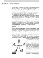
Virtual Local Area Network
VLANs allow network administrators to divide the network by designat-
ing certain ports as part of a logical network. Although several computers
or devices can be connected to the same physical network, they can be all
FIGURE 1.2 A Remote-Access VPN Solution Using Regular Internet POPs.
CHAPTER 1: Network Fundamentals 24
separated logically through the use of a VLAN. VLAN databases can provide
important details to any individual who is trying to discern the logical
breakup of the network. VLANs logically divide the network and affect the
traffic and security of a switched network.
Configuring VLANs
The first thing that might come to mind when we mention VLANs or Virtual
LANS is that somehow they don’t exist physically. They do exist and they
are very commonly used in the enterprise or corporate computing networks
to segment networks. In the past, to separate or segment networks, separate
pieces of hardware such as hubs or switches were used. It became very clear
that when hubs and switches only come in predefined capacities such as
5, 8, 12, 24, or even 36 ports, potentially we could be wasting resources by
not fully utilizing all the ports on these devices. In addition, as companies
expand and spread into different locations, it became difficult to have people
in the same departments on the same LAN segments. Someone envisioned
being able to reconfigure one physical device into multiple logical segments
and VLANs were born.
PHYSICAL NETWORKING MODELS
Just as size defines a network, so does the way it’s laid out. The topology of a
network is the physical layout of computers, hubs, routers, cables, and other
components. It provides a map of where things are, and how the network is
configured.
Although networks are often unique to one another, the topology of each
network will share characteristics with one another. Networks will either use
one of the topologies we’ll discuss, or in many cases a combination of them:
Bus
Star
Ring
Mesh
Point-to-point
Point-to-multipoint
Hybrid
Wireless
Physical Networking Models 25
BUS
Bus topologies are one of the most straightforward networks and are easy
to set up and install. As shown in Figure 1.3, all of the computers in a bus
topology are connected together using a single cable, which is called a trunk,
backbone, or segment. Coaxial cable is commonly used for the trunk, which
is the same cable that’s used to connect to your TV to receive cable televi-
sion. The computers are attached to the cable segment using T-connectors,
which get their name because they’re shaped like the letter T. Because all of
these computers use the same cable, only one computer can send packets of
data (which are electronic signals) onto the network at a time.
When a computer sends a packet of data onto the trunk, it is sent in both
directions so that every computer on the network has the chance to receive
it. Each of the computers on this type of topology listen to the network traffic,
so that they can determine whether any packets being sent over the network
are intended for them. When a computer listens to the network, any packets
that aren’t addressed to it are ignored, while any specifically addressed to it
are accepted. The exception to this is when a broadcast is made, which are
packets that are destined for every computer on the network.
Because the topology is linear, when data is sent over the trunk, it runs
the length of the cable. To prevent data signals from staying on the cable
indefinitely, the cable needs to be terminated at each end so electronic sig-
nals are absorbed when they reach the cable’s end. The terminator absorbs
the signal, so that the cable is clear for other computers to send packets
on the network. Without termination, a computer would send packets to
another computer over the trunk, and they would bounce back and forth
along the length of the cable until the network was brought down. To prevent
the signal from bouncing up and down the cable, terminators are attached at
both ends of the cable. Without termination, the entire network fails.
Bus topologies have several bene-
fits to organizations. Although we
mentioned that they are easy to set
up, they are also a passive topology.
In other words, when a computer is
FIGURE 1.3 A Bus Topology.
Exam Warning
One of the testable items on the Network+ exam is being able to identify a topology
based on either the description given, or by looking at a picture of a topology. Make
sure that you know each of the topologies covered in this section, and can identify them
simply by looking at them before taking the exam.