CompTIA Network+ Certification Study Guide part 7 pptx
Bạn đang xem bản rút gọn của tài liệu. Xem và tải ngay bản đầy đủ của tài liệu tại đây (92.05 KB, 10 trang )
CHAPTER 2: Network Media 46
CABLING AND CONNECTORS OVERVIEW
The media that carries data makes up the basic infrastructure of a network.
If you consider data as a vehicle that moves between two points; then cabling
and connectors are the highways and interchanges that allow data to access
and travel across that network. Connectors attached to the ends of the cables
are plugged into or coupled in some way with a network card or other device
on your network. In doing so, a physical link is created between this device
and others on your network. Just as a car uses an on ramp to enter a high-
way, the connector provides an access point for data to move along the cable
to its intended destination.
The purpose of a cable is to carry data across a network. A network card
passes an electronic signal onto a cable and a connector is used to connect
the cable to the network card or other device to the cable. The data, in the
form of an electronic signal, is passed through the connector to a wire or fiber
in the cable. Just as the wires in your house carry electricity to the lights and
wall sockets in each room, the cable carries these electronic signals to the
computers, printers or other network devices meant to receive them.
Although local area networks (LANs) of the past often used one type of
cabling, many LANs today use a combination of different cable types. This
is because different cables will carry the data at varying speeds and distances.
Although some cables can carry the data for a hundred meters or so, others
can span greater distances, connecting widely spaced areas. In the same way,
some cables will allow a network to transfer millions bits data, while others
can send a thousand times this amount. As we’ll see later in this chapter, the
features of a particular type of cable can vary greatly.
Because different types of cabling are available to use, it follows that there
are also different types of connectors that may be used. The connectors fit on
the ends of the cabling and are designed to hold the wires or fibers within the
cabling together, allowing them to make a connection when the connector is
plugged into or coupled with a network device. If you think of a cable used
on your telephone, each end of the phone cable has a connector that bundles
the wires in the cable together in a specific way, so they can make a connec-
tion when the cable is plugged into the corresponding telephone or wall jack.
The connectors on a network cable are the same, providing an interface for
a device to connect to a cable.
Fundamentals of Cabling
Cabling is the wire or fiber medium that is used to connect computers and
other network devices on your network together, and used to carry the data
that is transmitted between them. Although we’ll discuss each of the types
Cabling and Connectors Overview 47
of cabling in greater detail later in this chapter, be aware that there are three
types of physical media that can be used on a network:
Coaxial cable
Twisted-pair cable
Fiber-optic cable
Coaxial cable, also referred to as coax, is the same type of cabling you
see in most cable television installations today. A single copper wire at the
center of the cable core is used to carry the signals and is surrounded by lay-
ers of insulation that protect the wire and its transmissions. On networks,
there are higher grades and different types of coaxial that may be used: thin
(10Base2) or thick (10Base5) are two examples.
The thin and thick kinds of coaxial cabling refer to the thickness of the
cable. 10Base2 cabling, also known as Thinnet, is 0.25 in. while 10Base5
cabling, also known as Thicknet, is 0.5 in. Because a thicker wire was used
in 10Base5, it allows data to travel further than its thinner counterpart. This
made 10Base5 ideal as a backbone for early networks, although the increased
speeds and distances supported by fiber-optic cabling has become a better
solution for modern networks.
Twisted-pair cable is a type of cabling that’s used for telephone and net-
work communications. When we mentioned the cable used to connect your
phone to a wall jack, we were discussing a type of cable called twisted-pair.
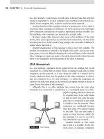
As shown in Figure 2.1, twisted-pair cables have one or more pairs of copper
wires that are insulated and twisted around one another, which prevents the
signals on the wires from interfering with one another. Common sources
of interference are electromagnetic
interference (EMI) and radio fre-
quency interference (RFI). Problems
may occur such as the untwisting of
pairs. In this case, the twisted pairs
may open up or loosen and will be
more susceptible to EMI and RFI.
As we’ll see later in this chapter,
there are different categories of
Note
A backbone segment is made up of high-speed lines and equipment normally located at
the very center of your network.
FIGURE 2.1 Twisted-Pair Wiring.
CHAPTER 2: Network Media 48
twisted-pair cabling, which are used for different purposes and have vary-
ing degrees of sensitivity to interference.
Twisted-pair cabling may be shielded or unshielded. The difference
between unshielded twisted-pair (UTP) and shielded twisted-pair (STP) is
that STP has an extra layer of aluminum/polyester between the wire and
the plastic covering. This acts as a shield against interference from outside
sources that could corrupt data carried on the copper wire.
Fiber-optic cabling is different from these other types of cabling, as it
doesn’t use copper wires to transmit data. Fiber-optic cables use glass or
plastic to transmit light pulses across the network. Because information is
transmitted at the speed of light, it can carry more information faster than
other types of cabling.
Fundamentals of Connectors
Connectors are used to hold the ends of the wires or fibers in a cable in place,
so that it can then be plugged into a network card or other equipment on
your network. As you can see when looking at the cable connectors used for
your phone and cable television, these connectors may be plastic or metal
and differ greatly in appearance. This makes them easy to identify both in
the real world and on the Network exam.
There are several different kinds of connectors that may be used with the
different types of cabling, which we’ll explain in detail later in this chapter.
They are as follows:
Bayonet-Neill-Concelman (BNC) is a type of locking connector used
to terminate coaxial cables. BNC is also referred to by many other
names such as Bayonet Network Connector, British Naval Connec-
tor, or Bayonet Nut Connector.
Registered jack (RJ) is used with twisted-pair cables. RJ-11 is used
for phone cables, while RJ-45 is a twisted-pair connector that is
commonly used in networks.
Standard connector (SC) is used with fiber-optic cabling.
Straight tip (ST) is used with fiber-optic cabling.
Local connector (LC) is used with fiber-optic cabling.
Mechanical transfer registered jack (MTRJ) is used with fiber-optic
cabling.
These different types of connectors attach a cable to network cards and
other devices in different ways. Some connectors, such as RJ-11, RJ-45, and
Media Issues 49
ST, are plugged into a port, whereas others such as BNC and ST connectors
have threading that is used to screw the connector into place. To put this
into a perspective of something you’re familiar with, the RJ connectors
are plugged in just as you would plug your phone cord into the telephone.
BNC connectors are screwed onto a corresponding port in the same way
you attach the cable used for cable television to the back of your TV. Once
the connector is attached to the network card or another device, it provides
a connection between the device and the physical media that carries data
across your network.
MEDIA ISSUES
As with anything dealing with networks, there are issues that you’ll need
to consider when deciding on what’s best for your organization. The dif-
ferent types of physical media available each have their own benefits and
vulnerabilities that can affect network performance and the amount of work
required to install, troubleshoot, and repair cabling. Some types of cabling
can carry more data at faster speeds and over longer distances. Other types
are more susceptible to interference that can corrupt data or have security
issues that make them more vulnerable to attack. By knowing the issues
related to each media type, you can make a better decision on which cabling
will best suit the needs of your network.
Interference
If you’ve ever listened to a radio during a storm, you’ve probably heard the
crackles and pops of static when lightning interferes with the radio transmis-
sion. Just as the electricity of lightning can interfere with radio signals, simi-
lar interference can effect the transmission of data across a network cable.
EMI is a low voltage, low current, high-frequency signal that can interfere
with the electronic signals transmitted over cabling. Because the EMI signals
come from outside sources and interrupt the information sent over cabling,
it is often referred to as noise.
EMI can result from numerous sources. Power lines, transformers, fluo-
rescent lights and fixtures, industrial tools, engines, and other machinery
and equipment that run on electricity can emit electromagnetic waves that
affect other devices and data transmitted over cabling. The electromagnetic
field generated by these devices is a natural byproduct of electricity being
passed through the wiring, and its effects are not only seen in cabling, but
also in other computer technology. For example, if you place a lamp or fan
near your monitor, you may find that the screen flickers because the EMI of
the lamp is causing interference with the monitor.
CHAPTER 2: Network Media 50
Similar to EMI is RFI, which is caused by electromagnetic radiation in the
radio frequency range. RFI can be caused by radio and television broadcast
towers, microwave satellite dishes, appliances, and furnaces. Just as with
EMI radiation, RFI can result in data being corrupted during transmission.
The effects of EMI or RFI can be reduced or eliminated by properly
grounding equipment, not placing cables close to sources of EMI or RFI, and
using cables that use shielding or are more resistant to EMI/RFI. A shield is
a material in the cabling that’s used to absorb EMI/RFI before it reaches the
wires that carry data. UTP is the most vulnerable type of cabling because it
doesn’t use any shielding to protect the wires in the cable. STP is more resis-
tant to EMI/RFI because a layer of aluminum/polyester exists between the
wire and the outer plastic covering of the cable. A similar shield is found in
coaxial cable, which uses a wire mesh or foil shielding in the cable. The only
cabling that is unaffected by EMI/RFI, however, is fiber-optic cabling, which
doesn’t contain any copper wiring and uses plastic or glass that is noncon-
ductive. Although we’ll discuss the internal components of these cables later
in this chapter, using cables that provide shielding or aren’t affected by EMI/
RFI will prevent data from being corrupted during transmission.
Another type of interference that can occur in cabling is crosstalk. Cross-
talk occurs when the electromagnetic field of one wire interferes with the
transmission of another. That is, the signals from one wire essentially bleed
onto another wire. You may have experienced this in a telephone system,
when you hear someone else’s conversation on your phone line. In networks,
this type of interference can cause a loss or corruption of data.
Crosstalk can be reduced or eliminated by moving the cables further
apart from one another or using cables that use shielding. As with EMI/RFI
interference, UTP is the most vulnerable to crosstalk, while STP and coaxial
cable have shielding that protects the wire from outside interference. Fiber-
optic cabling is immune from crosstalk because it uses light rather than
electronic signals to transmit data.
Bandwidth
Bandwidth is a measurement of the amount of data that can be passed over
a cable in a given amount of time. If you compare cabling to a highway, and
data to vehicles traveling along the highway, then bandwidth would be the
Exam Warning
Don’t get crosstalk confused with EMI. Remember that when one cable has its data com-
munications bleed onto another cable, it is crosstalk. EMI can come from any number of
sources, including florescent lights or machinery.
Media Issues 51
amount of traffic supported. Just as too many cars traveling on a highway
would cause a traffic jam, there is a limit to the amount of data a cable can
support before the network becomes bogged down.
Bandwidth is generally measured in increments of bits and bytes. A bit is
short for binary digit and is the smallest unit of data on a computer. When
information is processed or sent across a wire or circuit board, it is passed
as an electric current. The signal is either a high current or low current of
electricity and represented digitally by a 1 or 0. Each of these ones and zeros
is referred to as a bit, and 8 bits of data make a byte. A word is considered
4 bytes, which is essentially 32 bits … the same length as an IP (Internet
Protocol) address, which we will learn about in Chapter 6.
The bandwidth capacity of a network cable is usually measured in the
number of bits or bytes that can be transferred in a second. In modem con-
nections, thousands of bits may be sent, with each thousand referred to as
a kilobit per second (Kbps). In network cabling, considerably more data can
be sent more quickly. Bandwidth may be measured in megabits per second
(Mbps), with each megabit representing a million bits of data transmitted
each second, or in the gigabits per second (Gbps), meaning that 1000 mil-
lion bits of data are transferred for every 1 gigabit supported. Table 2.1 shows
the bandwidth capacity of different media standards, which we’ll discuss in
greater detail later in this chapter, and how this capacity varies depending on
the media being used.
Table 2.1
Bandwidth Capacity of Physical Media
Media Standard Cable Type Bandwidth Capacity
10Base2 Coax 10 Mbps
10Base5 Coax 10 Mbps
10BaseT UTP or STP (Category 3 or higher) 10 Mbps
100BaseTX UTP or STP (Category 5 or higher) 100 Mbps
10BaseFL Fiber-optic 10 Mbps
100BaseFX Fiber-optic 100 Mbps
1000BaseT UTP or STP (Category 5 or higher) 1 Gbps (1000 Mbps)
1000BaseSX Fiber-optic 1 Gbps (1000 Mbps)
1000BaseLX Fiber-optic 1 Gbps (1000 Mbps)
1000BaseCX Fiber-optic 1 Gbps (1000 Mbps)
10GbaseSR Fiber-optic 10 Gbps
10GbaseLX4 Fiber-optic 10 Gbps
10GbaseLR Fiber-optic 10 Gbps
CHAPTER 2: Network Media 52
If the amount of data exceeds the amount of bandwidth supported, the
cabling can become a bottleneck because the transmission speed will be
affected. Think about pouring water into a funnel, since the base of the fun-
nel is more narrow then the wide mouth on top if you pour the water too
quickly it will back up into the mouth of the funnel and spill over. The water
moves more slowly through the base since it is a narrower opening forcing
you to pour the water slowly. Data transfers work in much the same way.
If the data being transmitted on the cable is excessive for the cable’s maxi-
mum capability, then the transfer will be slowed. The amount of data being
transferred needs to be compatible with the cable type in place, otherwise
the outcome is a resulting network bottleneck. It should now make complete
sense to you why bandwidth can be precious, especially for your wide area
network (WAN) connections (discussed in more detail in Chapter 7). WAN
links are costly and you will likely want to use every ounce of bandwidth you
can squeeze out of it.
To follow a real world example, if 10BaseT UTP cable was used to transfer
data between floors of a building, then approximately 10 Mbps of data could be
sent per second. If considerably more than this amount was being sent across
the network on a routine basis, then cabling that supported a higher bandwidth
(such as fiber optic) would be needed. When designing a network, it is important
to consider the amount of data that will be transferred so the proper cabling can
be initially installed. As the requirements of the network grow, replacing existing
cabling with cables that support a higher bandwidth capacity may be necessary.
Length Problems
The length of cabling is an important consideration when deciding on the
cable that will be used for a network. As signals travel the length of a cable,
they will weaken over distance. The signals will eventually degrade until
they reach the point where the data is lost. When this occurs, it is referred
to as attenuation.
Test Day Tip
An easy way of remembering the maximum bandwidth of the various media standards is
to look at the number at the front of the standard, which refers to the number of mega-
bits supported. In looking at 10Base5, the 10 symbolizes that the maximum transmission
speed is 10 Mbps, while the word Base indicates that it is using a baseband technology
(as opposed to broadband). The final portion of the media standard varies in meaning.
Originally, the number at the end indicated the maximum distance of the cable. For
example, the 5 in 10Base5 indicates that it has a maximum distance of 500 m, while
the 2 in 10Base2 was a rounded-up indication of its 185 m maximum distance. This
changed, however, with 10BaseT, which signifies that twisted-pair cabling is used.
Media Issues 53
Because attenuation can occur, it is important that you don’t exceed the
maximum distance of a cable. Table 2.2 shows the maximum lengths of various
media standards, which we’ll discuss in greater detail later in this chapter. As
you can see, physical media can have a maximum distance ranging from hun-
dreds of meters to kilometers in length. If a cable has to be run longer than its
maximum distance, then the signal will have to be regenerated. In the past, a
device called a repeater performed this task. As we’ll discuss in the next chapter,
repeaters aren’t generally found on modern networks, but this same functional-
ity is found in other network devices, such as switches, routers, and hubs.
Fiber-optic cabling doesn’t suffer from attenuation as copper cabling does.
Part of the electric signal passed along a copper wire will be absorbed by the
cable and weaken over distance, but since fiber optic uses light passed over
glass or plastic fiber it doesn’t suffer from the same problems. Although
Table 2.2
Maximum Distance of Physical Media
Media Standard Cable Type Maximum Length
10Base2 Coax 185 m
10Base5 Coax 500 m
10BaseT UTP or STP (Category 3 or higher) 100 m
100BaseTX UTP or STP (Category 5 or higher) 100 m
10BaseFL Fiber-optic 2 km
100BaseFX Fiber-optic 400 m (half-duplex) or 2 km
(full-duplex)
1000BaseT UTP or STP (Category 5 or higher) 100 m
1000BaseSX Fiber-optic 550 m (MMF)
1000BaseLX Fiber-optic 550 m (MMF) or up to 10 km
(SMF)
1000BaseCX Fiber-optic 100 m
10GbaseSR Fiber-optic Up to 300 m over 2000 MHz km
MMF
10GbaseLX4 Fiber-optic Up to 10 km over SMF
10GbaseLR Fiber-optic Up to 10 km over SMF
Test Day Tip
Review the maximum cable lengths and the transmission speeds associated with the dif-
ferent media types before going into the exam. To ensure you know them, have someone
quiz you on the various elements of each media standard. You can expect to see ques-
tions related to these elements of physical media on the exam.
CHAPTER 2: Network Media 54
twisted-pair and coaxial cables can span a distance of hundreds of meters,
signals will run along fiber-optic cable for kilometers without any noticeable
signal degradation. It’s for this reason that fiber-optic cabling is used for con-
necting locations of a network that are separated by significant distance.
Security Issues
The security of cabling is another important issue that should be considered
before installing a particular kind of cabling. Different organizations and
locations may require different types of cabling to meet the security needs
outlined in policies or regulations. In other situations, such as a small office
home office (SOHO), security may be a minor issue. Because needs differ,
you should try to establish what the security needs are before installation
begins. In determining the kind of cable you’ll install, you will also need to
be aware of security issues that are inherent to certain types of cabling.
If you’ve watched any crime dramas on television, you’ve probably heard
of wiretapping. Often, this refers to gaining access and listening to some-
one’s telephone line without the person knowing about it. However, as we’ve
said, the same or similar cabling used for voice communication is also used
in networking. Wiretapping is as much a security risk for network cabling as
it is for a business telephone line.
Wiretapping involves gaining physical access to a network cable. The
cable must be cut or pierced so that the wires inside the cable can be accessed
and then spliced or tapped. Because of the shield in STP cabling, this is more
difficult to do than with UTP. Older networks that use coaxial cabling often
recognize the risk of wiretapping because tapping is required on 10Base5
(Thicknet) cables to add new workstations. A tool called a vampire tap is
used to clamp onto the coaxial cable and pierce it. A needle is then dropped
into the hole in the cable, so that contact is made with the wire inside of the
cable. This tap provides a connection so that 10Base2 cabling can be used to
connect a computer to the cable and access data traveling along the cable.
Fiber-optic cabling is the least susceptible to wiretapping because of the glass
or plastic fibers used to carry the data. It is difficult to tap into the cable without
causing damage, although optical vampire taps do exist that allow a tap to be per-
formed by clamping onto the cable. Generally though, a tap requires cutting the
cable before tapping it, which may provide an obvious clue that a problem exists.
Another security issue related to cables is eavesdropping. Eavesdropping
is the act of listening to data being sent over the wire without actually pierc-
ing the cable. As we learned earlier when we discussed crosstalk and EMI
from other cables, the signals of a cable can bleed off and be picked up by
other wires in neighboring cables. The same factors that make it possible for
EMI to cause interference with cabling also make it possible for someone
to obtain data from the cable without piercing it. To minimize the risk of
Media Issues 55
eavesdropping, you should use cabling that is less susceptible to EMI (STP
or coaxial) or immune to it altogether (fiber optic).
Installation
The level of difficulty in installing physical media varies depending on the
type used and where the cabling is being installed. In some situations, such
as a home office, it can be incredibly simple, but in others, such as running
cable down an elevator shaft to connect two floors of a building, the instal-
lation can be challenging. Depending on the cabling and the location, you
may be able to easily install the cabling yourself, or may opt to outsource to
a company that specializes in cable installation.
Installation of twisted-pair cable is relatively easy. UTP is similar to the
cable used for phone lines, so it is thinner and more flexible than other types of
cabling, making it easier to get around corners. STP is more difficult than UTP
because of the shielding. STP requires an electrical ground with the connec-
tors, which is why it is easier to use pre-wired cables that already have the con-
nectors installed. It is never recommended that you make cable if you either
don’t know how, or don’t have equipment to test the cable that you made.
STP is thicker than UTP, making it more rigid, which can make it more
difficult to install around corners. Although the shielding provides greater
benefits against EMI, the installation of the cabling can be more problem-
atic. STP is also more difficult to make and more expensive than UTP.
DAMAGE AND DEFENSE…
Physical Security
Physical security is an important part of any network.
In terms of cabling, you should try to keep as much
cabling as possible out of public reach. Rather than run-
ning cable in the open, or having it accessible in waiting
rooms or reception areas, most of your cabling should
be run in secured conduits protected from damage
behind walls, floors, or ceilings, with wall jacks placed
to plug into the network in areas close to desks. Even if
you do not use special cable management equipment,
you can still keep the cabling neat and secure and out
of reach so that you don’t have issues with cut cables,
broken cables, and so on. You don’t want members of
the public being able to access connections or cabling.
You should also perform routine inspections of
cabling for physical damage, as this may indicate
attempts to tap the wires and acquire data, or just alert
you to a simple problem you may be able to proactively
take care of before it gets worse. As mentioned in this
section, fiber-optic cabling and shielded cable will help
to protect your cable from security issues, although
fiber-optic cabling is very sensitive to the touch and easy
to break if handled incorrectly. It is also very difficult to
install and repairs can be difficult and costly.
Remember that physical security is important and
that in high security areas, more drastic and expen-
sive methods are also available to add new levels of
security, if needed, such as placing cables in steel con-
duits, or using conduits that are pressurized with gas
and use monitors to determine pressure changes. This
works like an alarm that someone may be attempting
to access a cable.