CompTIA Network+ Certification Study Guide part 8 pdf
Bạn đang xem bản rút gọn của tài liệu. Xem và tải ngay bản đầy đủ của tài liệu tại đây (88.6 KB, 10 trang )
CHAPTER 2: Network Media 56
Coaxial cable is also relatively easy to install. If you’ve ever extended the
cable for your cable TV, you’re probably familiar with some of the ease and
difficulty you’ll face. The connectors for coaxial cable are fairly simple to
install, but the cable is relatively thick and rigid and can require some finesse
in navigating it around corners.
Installation of fiber-optic cabling can be difficult, which is why many
companies outsource the job of installing and maintaining it to other firms,
such as a local phone company. Not only is it somewhat difficult to install,
but it is also difficult to test. Cable testers are your insurance that a line is
operational so you do not have to come back to fix it or spend more time
troubleshooting it immediately after installation.
Because glass or plastic is used to carry the data, connecting two pieces
of cabling together can provide difficulties, as they must be fused together.
Because of the cost of fiber-optic cables, it generally isn’t installed throughout
an entire network. Rather, fiber is often used as a backbone for networks, con-
necting different buildings together so that data can be transmitted quickly
between them. Although other types of cabling are used within the build-
ings, a local phone company or another firm that specializes in fiber- optic
installation may be used to install and maintain the fiber-optic cabling.
Troubleshooting
Experienced network administrators know that cabling is one of the most
common causes of network failure. For this reason, you should check cabling
early in the network troubleshooting process. Because you are often respond-
ing to a single workstation or group of computers that can’t communicate
with the network, start at that point and then work outward. There is no
point in checking the backbone of the network if a single computer is having
a problem. Also, because the workstation is probably using twisted-pair or
10Base2 coaxial cable, it is also the easiest to check first.
Most often, the cable running from the workstation to the wall jack is the
one that will be the problem. This cable receives the most abuse and may
be damaged. Sometimes you may fix the problem by simply plugging the
cable back in if it has fallen out or has otherwise been unplugged. Because of
this, you should perform a visual inspection of cabling as a first step. Sim-
ply reviewing the cables and surrounding area will provide clues of possible
wiretapping, tampering, electrical work that may have affected the cabling,
or other things that are out of the ordinary.
If you believe a bad cable may be the culprit of a network-related prob-
lem, the most logical step is to test your hypothesis by replacing the cable
with a known good cable. The results are simple: if you can communicate
once again, then the old cable was the source of the problem. If you still
Media Issues 57
cannot communicate with the known good cable, you need to continue
troubleshooting or find another cable to test.
In troubleshooting cabling, you should also be aware that some apparent
cabling problems may actually be hardware-related. You should determine
whether the network interface card (NIC), which we’ll discuss in Chapter 3,
is faulty and determine if it is communicating with the network properly
or not.
As you work outward from the problem, look for possible sources of inter-
ference, such as florescent lighting, machinery, or cables that are too close to
each other. As we discussed earlier, interference from such sources can cause
corrupt data and disrupt network communications.
Because there is a limit to how far cable can run before it suffers attenu-
ation, you should also check cable distances. If the maximum distance for
cabling has been reached, then you may need to install a device that will
regenerate the data and pass it along to the next segment. We’ll discuss such
devices in Chapter 3.
Using tools that are designed for troubleshooting cable problems is
another important factor in solving such problems quickly. As we’ll see later
in this chapter, there are a number of tools that can be used to check for
breaks. These tools are a necessity to find where a problem exists in the
cabling and will save considerable time in solving cabling issues.
Repair
The ease with which different cabling types can be repaired depends on the
cable type itself. The repair of copper cable is relatively easy. As we’ll see later
in this chapter when we discuss cabling and cable creation, twisted-pair and
coaxial cabling may require replacement of a bad section with a new section
of cable. Twisted-pair may require rewiring the individual wires of a new sec-
tion to a connector, while coaxial could use male and female barrel connectors
to attach a new section of cable to an existing one. Because copper wire is
involved, this makes it a relatively simple procedure. Because of how inexpen-
sive coaxial and twisted-pair cables are, it is often easier to simply replace the
segment of cable with a new one, unless it is a particularly long segment.
Repair of fiber-optic cabling is difficult and requires professional training.
If there is a bad section that has to be replaced, connecting a new section
would require using either electric fusion or a chemical epoxy process to con-
nect the segments together. Unless you have the necessary tools and training
to perform such repairs, it is generally wiser to have a firm that specializes
in such repairs do it for you. Repair of fiber-optic cable is not just difficult; it
is also costly. Most times, organizations need only a single fiber run, so it is
cost-prohibitive to do this work yourself.
CHAPTER 2: Network Media 58
CABLE TESTERS AND TROUBLESHOOTING
In many troubleshooting sessions, there is a time where a simple isolation
of problems is just not feasible. In such situations, you will need to rely on
electronic tools to determine what and where the problem is. Cable testers
are tools that can analyze the capability of a cable to carry signals and can
find breaks or other problems in the wire. In addition to cable testers, there
are also other tools that can be used in the troubleshooting process to identify
problems on your network. In the sections that follow, we will look at the
most common ones.
Tone Generator (Fox and Hound)
The tone generator is used to perform tests on phone and network lines by
clipping to a wire, terminal panel, or standard modular jack, and will aid in
the identification of wires during the wire tracing process. A tone generator
can be connected to a data or voice line and it is used to find out where a
cable end may be. A test signal is sent across a wire pair to transmit a tone
(the word tone is from the usage in the voice arena – dial tone). You can
quickly and easily trace pairs and locate broken pairs in the cabling, even
those buried deep in the walls.
To use a tone generator, you begin by attaching the fox to the cable, jack,
or panel that you would like to trace, and you continue with the hound on the
other end of the cable to find the fox’s tone. When you find the tone, you will
know that you have correctly tracked the cable. This is very helpful in determin-
ing which cable in a group of many cables, such as a wiring closet, has gone bad
and needs to be replaced, or it can help you determine which cable is connected
where if the cable installer did not correctly or properly mark the patch panel.
Time Domain Reflectometer
A time domain reflectometer (TDR) also uses signals it sends down the
cable to identify problems. An electronic pulse travels down the cable until
it is reflected back, much like how sonar technology works. The TDR
then calculates the distance down the cable that the signal traveled before
being reflected by measuring the amount of time it took for the signal to
be returned. If this distance is less than your overall cable length, a cable
Note
For more information on how to make and test fiber-optic cabling, visit www.thefoa.org/
tech/FAQS/FAQ-TEST.HTM
Cable Testers and Troubleshooting 59
problem exists and is occurring at the measured distance from your location
(yes, this means that it is in the most inconvenient location possible – it is
a law of networking that when something breaks, it will be in the worst pos-
sible place).
Wire Map Tester
A wire map tester is generally used on networks that use twisted-pair cabling.
It will test for opens, shorts, and crossed pairs, and will provide information
that may indicate improper wiring. Because they are a low-cost cable tester,
they generally provide fewer features than other cable testers, such as TDRs.
Oscilloscope
An oscilloscope can determine if there are shorts, crimps, or attenuation in the
cable. An oscilloscope formats its output in a graphical format. Oscilloscopes
are commonly used to test cables that have been recently run through walls
to ensure that there are no problems with the cable prior to using it.
Network Monitors and Protocol Analyzers
Network monitors and protocol analyzers monitor traffic on the network
and display the packets that have been transmitted across the network. If
a particular type of packet is not being transmitted across the network, the
problem may lie with that particular packet type. Because the network moni-
tor enables you to view the contents of all packets on the network, in many
cases, viewing the contents of these packets is considered unethical or even
illegal. As such, you should determine the company’s policy on using these
tools before implementing them as part of the troubleshooting process.
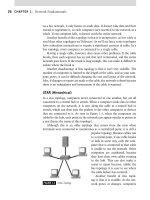
Crossover Cable
A crossover cable appears to be just another twisted-pair cable, but two wires
are crossed, which makes the cable unfit for plugging into a computer and a
hub for normal use. The crossover cable is used to connect two computers
to each other directly, without the use of a hub.
A crossover cable is also used to connect hubs in the event you need
to cascade them. If you were to substitute a crossover cable for a regular
twisted-pair cable to connect two hubs, it would not work correctly. There-
fore, it is important that you mark your crossover cables or use a different
color cable to designate a crossover cable. Many companies use yellow or
black cables for regular cables and blue for crossover cables. You will not
need many crossover cables, and you can make them yourself if you have
CHAPTER 2: Network Media 60
the correct pinout. There are a few things to remember about making a
crossover cable. First, make sure you label it or know how to distinguish it
from other cables such as a straight through. This is because you may end up
using the wrong type of cable to connect a computer to the network and that
may be the cause of your issues, when all along it could have been prevented
with the proper labeling of the cable. Exercise 2.1 shows you how to make a
crossover cable from a standard straight through cable.
EXERCISE 2.1 Making a Crossover Cable
This exercise will show you how to properly construct a crossover network
cable from a preexisting straight through cable. In this exercise you will need
tools to help you cut and create the wire. These tools (which will be discussed
throughout the text and can be further researched online) are as follows.
You will need a preexisting cable. If you are already familiar with mak-
ing cable, you can use a fresh length from a bulk cable spool if you have one
available, but if not, then you can use a preexisting cable to perform this
task. You will definitely want it to be Category 5 or above. You will also need
connectors (RJ-45 modular plugs). You will also need a cutter to cut the wire.
A cutter can be a standard pair of scissors or a high-end cutting tool made
specifically for the job of cutting cable. Because cutting cable has to be exact,
neat, and (most importantly) the eight wires have to be cut evenly to fit in the
RJ-45 connector, it’s important to consider using the right tool for the job. A
crimper is also needed to squeeze the RJ-45 connector onto the cable making
it a permanent fit. Once the connector has been crimped onto the cable, you
should not attempt to remove it. Mistakes here should be met with a new cut
of the end of the Category 5 cable and a new end created. You will also need
a stripper to pull the cable jacketing off the wire to expose it. Make sure that
you do not damage any of the wires. Although making cable can be easy, a lot
of care needs to go into its creation for it to work properly. Now that you have
your tools ready and the cable you want to turn into a crossover cable, let’s
look at the actual steps involved in making the cuts and creating the cable.
Take a new (or tested) Category 5 UTP cable and ensure it is 1.
rated properly (check the outer jacket to ensure that this cable is
Category 5 UTP). Now that has been determined, take your cutter
and snip off one of the ends of the cable you are about to make into
a crossover cable.
Once you have made the cut, ensure that the cut is clean, meaning 2.
that there are eight wires cut evenly across with a hint of copper
Cable Testers and Troubleshooting 61
showing at the tip of each exposed wire. The copper ends will touch
the contacts located within the RJ-45 connector. This is essentially
why the cut has to be clean; it has to fit neatly into the connector
and make connection with the contacts.
Now, strip off some of the excess jacket (about 1 to 3 inches) and 3.
reveal the inside wires so that you can work with them. You will
have to untwist the pairs a bit to get them into the RJ-45 connec-
tor, but be careful not to untwist them too much, as the twists are
what keep the phenomenon of crosstalk down.
Once you have stripped off the jacket to expose the wires, you will 4.
need to spread the wires apart (carefully) in a fan so that you can
clearly see the colors on each of the individual wires; four pairs of
two wires each, each following a tip/ring combination of specific
color codes.
Make absolutely sure that you hold on to the base of the jacket 5.
so that you can keep the twists tight at the base where you cut
the wire’s jacket. You do not want the wires to become untwisted
down inside the jacket. Once you are ready, you have to reorder
the cables so that the transmit (TX) and receive (RX) channels
are reversed – hence the name crossover. Later in this chapter, we
will look at the wiring pairs in detail. To make a crossover cable,
all you need to do is change one of the cable ends to a different
standard.
568a – standard end on one side, 568b – standard on the other end 6.
makes a crossover cable. Although cabling standards at this depth
are not covered in the Network exam, it’s still very important
to know as a network technician. You will learn about the cabling
pinouts later in the chapter.
Once you insert the cable pairs into the RJ-45 connector, you need 7.
to make absolutely sure that no cable is exposed outside of the RJ-
45 connector. What this means is that if you cut the cable too long,
it will have exposed wires, as the jacket is not able to protect them.
Make sure that you cut the jacket so that the connector covers it so
you don’t have any open leakage for interference or wire pairs that
can untwist themselves.
Take your crimper and insert the new end of the cable into it with 8.
the RJ-45 connector. Once you are ready, firmly place even pressure
on the crimper so that the connector is seated and will not open
CHAPTER 2: Network Media 62
up. Usually, once you crimp a connector, it cannot be uncrimped so
if you make a mistake, you will be cutting the end off and starting
again.
Now that you have finished the crimping job, you should have a 9.
perfectly good crossover cable that you can use that can be used
for any connection that requires it. Make sure you test the cable;
otherwise, you may experience other problems and not know where
to look or troubleshoot.
Hardware Loopback Adapter
A hardware loopback adapter is a way to test the ports on a system without
having to connect to an external device. For example, you can use a serial
loopback adapter to verify that a transmitted signal is leaving your serial port
and returning through the loopback adapter, ensuring that your serial port is
working correctly.
Cable Tester
Cable testers provide a variety of tests that can be performed on network
cabling. The features of a handheld cable tester will vary, so you should refer
to the documentation that comes with the tester to familiarize yourself with
what it can do and how the tests are performed. Some high-end testers will
also combine the features of several testers, such as providing the features of
a wire map tester and a TDR. A number of cable testers also have an auto-
test feature, which provides the ability to automatically perform a series of
tests on the cable, allowing you to review the results of each individual test.
In using a cable tester, you would check the segments of cable that are
suspected to have a problem. For example, if you were performing a test on a
network that uses 10Base2, you might separate the cable at a midway point.
You could then check each half of the cable to determine which half has the
problem. Once this is done, you could then perform the same test by check-
ing the cable at the halfway point of that section, and repeat this until you
have determined where the defect in the cable is located.
Note
A crossover cable can be used to uplink hubs and switches to each other. However,
some hubs and switching devices use autosense or have a manual way to switch the port
to a crossover port.
Cabling 63
SIMPLEX, HALF-DUPLEX, AND FULL-DUPLEX
When data travels across the medium, it travels in a certain direction. To
describe the movement of data across communication channels, certain terms
are used, including:
Simplex, which refers to data moving in a single direction.
Half-duplex, which means data travel in both ways on the medium,
but in only one direction at a time.
Full duplex, which means data travel in both directions
simultaneously.
Although these terms are often associated with network devices, as we
proceed in this chapter, we will discuss how certain methods of network
communication support simplex, half-duplex, or full duplex.
CABLING
Cabling isn’t just a term that refers to the cable being used. It is also a term
that refers to the act of installing the cable and the work performed before
installation begins. Because coaxial cable and twisted-pair cable are copper
cables, and fiber-optic cable uses glass or plastic fibers, different issues may
arise for each type of cable. As we look at these types of cabling, we’ll see that
there are other significant differences in how they are created and installed.
Copper Cabling
Installation of cable requires a number of different tools. Because the major
part of cable installation consists of running the cable where you want it and
attaching the appropriate connectors at each end, having the right tools is
crucial. Some of the tools will be common to any installation, such as elec-
tric drills to drill holes in walls, while others are specific to the cable itself.
Tools are used to cut and strip the cable and to attach the proper connector
to the end of the cable. These include:
Cable cutter, which is used to cut the cable to the size you need.
Cable stripper, which is used to strip the cable jacket and expose the
copper wire inside.
Crimp tool, which is used to attach the connectors to the cable.
Connectors that will be attached at the ends of the cable.
CHAPTER 2: Network Media 64
During the installation there are several points that need to be considered,
including the pulling force used on the cable. The pulling force of cabling
refers to the amount of force or tension that can be placed on the cable with-
out damaging it. In other words, it is how hard you can pull on the cable
when you’re installing or working with it. For example, with Category 5
UTP cabling, if more than 25 pounds of force is applied to the cabling during
installation, then it may be damaged and no longer meet the specifications
associated with it. It is important that you refer to the pull tension specifica-
tions of the cabling being used before installation begins.
The minimum bend radius of a cable refers to how far the cable can be
bent before it is damaged. If a cable is bent too far, the wire or other compo-
nents in the cable can crack or break, or the electrical characteristics of the
cable can be otherwise affected. Category 5 UTP cables allow a bend radius
of four times the cable’s diameter. For example, if the cable is 1/4 inch in
diameter, you can bend it 1 inch. Although the bend radius of cable can vary,
depending on the materials making up the cable, it is generally four, six, or
10 times the diameter of the cable.
Fiber Cabling
Fiber cabling also has bend radius and pull force ratings, and these will vary
depending on the type of fiber cabling used and the number of fibers in the
cable. The bend radius is usually specified with the cable, but will generally
follow the rule of 10 times the outside diameter of the cable. The pulling force
of fiber-optic cabling can also vary, with specifications ranging from 50 pounds
to a few hundred pounds. If a string is used to pull the cable through areas
during installation, at no time should you attach the pulling string to the
fiber strands, as this will damage the fibers and make the cable unusable.
During installation, special tools will be needed to strip the cable so that
the appropriate connector can be attached. These include:
Cable stripper or ring tool, which is used to remove the plastic
jacket of the cable without damaging the fibers.
Kevlar shears, which is used to cut the kevlar inside the fiber-optic cable.
Connectors that will be attached at the ends of the cable.
Preparing Copper Cable
Preparing cable basically involves measuring out the amount of cable needed,
exposing the wire inside of the cable, and attaching a connector. Although
this is obviously a compressed description of what has to be done, preparing
copper cable is actually relatively easy.
Cabling 65
The first step in preparing a cable is determining how much is needed
for a particular run. Because you will probably be pulling the cable through
false ceilings or areas that may be somewhat difficult to measure with a
measuring tape, the easiest way of determining how much cable is needed
is running the cable along the floor. By unrolling the cable along walkways
where the cable will actually run through walls and ceilings, you will get
a reasonable measurement of how much cable will go into a segment. It
is important, however, to account for a little extra slack that may be nec-
essary for cornering or to simply make it easier to work with the cable.
Once you’ve determined how much cable is needed, use a cable cutter to
cut the cable.
After you’ve got the proper length of cable, you will then need to strip
the cable to expose the wires. Using a cable stripper, you remove the outer
jacket of the cable. With UTP, you would remove about 3/4 of an inch from
the cable, and then untwist the wires within the cable so you can work with
them. Because four pairs of wires are used, this means that you will be work-
ing with eight wires that use a particular color code. The color code for UTP
wiring is described in the next section.
Once the wires are untwisted, you trim the leads of all eight wires to a
length of approximately 1/2 inch. Because the wires are thin, you should
be able to cut all of them with a wire cutter simultaneously, ensuring they
are all the same length. Having prepared the wires in this way, you are now
ready to attach the cable to an RJ-45 connector.
UTP contains several sets of wires that are attached to an RJ-45 connec-
tor in a specific way. Once the leads are aligned, you insert them into the
connector and push the wires forward until the copper wires can be seen
through the transparent end of the connector. The connector and the cable
are then inserted into a crimp tool, and with the wires pressed against the
end of the connector, you squeeze the crimp tool’s handle for a few seconds.
Once this is done, the connector is now firmly attached to the cable and is
ready for installation.
Twisted-Pair Color Codes
If you look inside a twisted-pair cable, you’ll notice that the plastic
sheaths covering the wires are colored differently. Twisted-pair cabling use
color codes to specify the purpose of each wire and to make them eas-
ily identifiable. Because each wire belongs to a pair, the colors of each
pair are the same, with one solid and the other striped. Table 2.3 shows
the color scheme that corresponds to the Electronic Industry Association/
Telecommunications Industry Association’s Standard 568B used for a
four-pair UTP wire.