CompTIA Network+ Certification Study Guide part 9 pptx
Bạn đang xem bản rút gọn của tài liệu. Xem và tải ngay bản đầy đủ của tài liệu tại đây (85.83 KB, 10 trang )
CHAPTER 2: Network Media 66
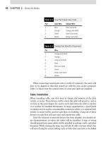
When connecting twisted-pair wire to an RJ-45 connector, the wires will
have to be aligned so that they match up with the pins of the connector.
Table 2.4 shows how the various wires of a four pair cable are installed.
Cable Installation
When installing cable, you first need to choose the location of the hub,
switch, or router. These devices will be where the cable will attach to, and as
we’ll see in the next chapter, are used to move data from one cable to another
so it reaches its intended destination. In larger organizations a patch panel
or cabinet may be used to accommodate numerous cables, or a separate hub,
switch, or router will be used for each floor of a building. Using one of these
devices on each floor will save time and require less cable.
Once the location of network devices has been decided, you should cre-
ate documentation on where the cables will be installed. A map of wiring
should include how many cables will be installed in ceilings, walls, and other
locations. While creating the map, you will also be able to review issues that
will arise during the actual cabling, such as holes that may have to be drilled
Table 2.3
Four-Pair Cable Color Code
Pair Solid Wire Striped Wire
1 Blue Blue and white
2 Orange Orange and white
3 Green Green and white
4 Brown Brown and white
Table 2.4
Twisted-Pair Wire/Pin Placement
Pin Wire
1 Orange and white
2 Orange
3 Green and white
4 Blue
5 Blue and white
6 Green
7 Brown and white
8 Brown
Cable Management 67
or vertical runs of cabling down elevator shafts. When determining how
the cable should run from an outlet to a hub, switch, or router, you should
remember to keep the cabling at least three feet away from fluorescent lights
and other sources of EMI.
Cables should be tested before they’re actually installed. Even if new
cable is being used for the installation, this doesn’t guarantee that it isn’t
damaged in some way. It is easier to test the cable before installation than
to determine where a section of bad cabling resides after installation is
complete.
Once you’re ready to actually start running the cabling along the paths
you’ve planned out, you should ensure that you actually have more cable
than is needed left on the roll. In running 100 feet of cable, you don’t want to
find there is only 90 feet of cable left in the box. Having extra cabling will also
ensure that you have enough slack to navigate the cable without problems.
Each end of a cable should be clearly marked, using masking tape or some
other form of labeling. Because you may be installing several runs of cable at
a time, you don’t want to be confused as to which cable runs to a particular
computer or location. By labeling the cables, this confusion is removed, and
you’ll be able to focus on the installation.
If you need to bundle cable, you should only use cable ties. Cable ties are
sturdy plastic strips that attach cables together into a ring. When using them,
however, you should allow enough space to fit a finger into the cable tie.
Having a cable tie too tight can damage the cables and make it more difficult
to cut when a cable has to be replaced. Using cable ties is the safest method
of keeping cables together, as staples or other methods can damage cable.
CABLE MANAGEMENT
Cable management and termination of cabling runs becomes important
when working as a Network technician. You have learned how cable is
used to connect devices to networks, but how is the cabling managed? When
working on a network, it’s likely you will be asked to connect a device to it,
but how does it all interconnect? The answers to these questions are simple.
When working in a Star-based network, you will likely have a central con-
centrator acting as a backbone for the entire switched and routed network.
Because of this, it’s important to understand how cabling runs through your
walls, through cubicles and anywhere else through your facilities.
Termination devices such as a 66 block or a 110 block are commonly
used to provide termination point and are generally located in wiring clos-
ets in your facility. This makes it easy to now take those runs of let’s say
CHAPTER 2: Network Media 68
50 cables, and bundle them safely and keep them secure and ultimately run
them to the central switch or backbone. In the wiring closed, patch panels
are used to connection RJ-45 or RJ-11 connectors so that moving systems
becomes quick and easy. No need to cut and recut and crimp and test cable –
just move a cable from one port to the other to facilitate a move. As long
as your network and cable runs are documented and kept up to date, you
will always have a very flexible routine in which to add and remove or move
nodes around your network. Devices such as cross connections, terminators,
termination blocks and the switch, and router ports you connect together
offer a great deal of flexibility and ability to grow to larger sizes without a
great deal of complication.
For the Network exam, you will need to know how to install commonly
used wiring distribution systems. Distribution systems are nothing more
than a term used to describe the hierarchical system of cross connections
that lead to a local private branch exchange (PBX), central concentrator or
the central office (CO) or elsewhere. You will also need to know how to use
patch panels, 66 or 110 blocks, deploy cable management and terminate
devices correctly. Next, we will take a close look at how patch panels and
other termination devices are used to connect to other termination points
on your network.
Patch Panels
Patch panels are ideal when used to allow for quick configuration manage-
ment ability. Need to move a computer? Simple – just move a cable or “punch
down” the connection. The term punch is used as slang when referring to
the use of a punch down tool which is used to terminate copper wire on a
termination block such as a 66 block, or 110 block.
66 Block
When you want to terminate your connections you will want to connect to a
66 block. When you want to terminate a connection on a 66 block, you need
to be careful not to untwist the pairs as this will introduce the possibility of
corrupted data, crosstalk, or other interference issues.
66 block type cross connects are used primarily for voice connection,
although they can be used for data.
Exam Warning
You will use the term cross connect often while working as a technician. For the exam it’s
important to remember this term. The term is used as a reference to the cable that runs
from one block to another, generally 25-pair cable.
LAN Technologies and Standards 69
110 Block
When you want to terminate your connections you will want to connect
to a 110 block. The 110 block is used (primarily) with data connections.
Although there are newer patch panels that are used and have to some degree
replaced the 100 block, there are many networks out there today that still
have them implemented. As with any other termination point, connections
need to be made carefully with a punch down (or impact) tool. You need to
be careful and make solid connections to the block as a loose wire may cause
connection issues or other problems.
Demarc
Demarc is a term used to describe where the providers equipment ends and
the private network begins. It is also referred to as the termination point
where telecommunications from telephone companies inside a facility or
building. Demarc extension is a common term used to describe cabling used
to connect to a router, switch, or other device from the smart jack.
Smart Jack
The smart jack is a term used to describe the box (or case) and internal cards
(and other hardware) where you terminate your router or switching device
to get access to the lease line companies circuit. For example, you could
connect a RJ-45- or RJ-48-based connector into a T1 smart jack and then
connect it to your router or CSU.
LAN TECHNOLOGIES AND STANDARDS
In discussing the physical media that may be used on your network, it’s
important to understand the technologies that are used on them. Although
we’ll discuss individual components of the network and technologies related
to them throughout this book, we’ll pause here to look at several technologies
related to physical media. As networking technologies have developed over
the years, it became apparent that standards were necessary so components
of a network could work together effectively, and how data is transferred
Exam Warning
Punch down (or impact) tools are handy for working with termination devices. You should
know that the cutting blade and shape of the impact tool is different for 66 block connec-
tions and 110 block connections. Make sure that you use the appropriate tool tip when
terminating your cables. You should also test the run and any other cables you are using.
CHAPTER 2: Network Media 70
over the network cable. These standards include Ethernet, Fast Ethernet,
and Gigabit Ethernet.
Ethernet
Ethernet is the standard for most of the networks today. As we discussed in
the previous chapter, Bob Metcalfe originally developed Ethernet as a tech-
nology that networked together remote computers. Digital, Intel, and Xerox
took the original specifications and extended it to accommodate speeds of
10 Mbps using coaxial cable or specific categories of twisted-pair cabling. In
1990, Ethernet was standardized by the 802.3 committee, and specifications
under this correspond to 10Base2, 10Base5, and 10BaseT (each of which
we’ll discuss later in this chapter).
A major component of Ethernet is the use of Carrier Sense Multiple
Access with Collision Detection (CSMA/CD) for access to the physical
medium. CSMA/CD keeps devices on the network from interfering with one
another when trying to transmit; when they do interfere with each other,
a collision has occurred. To reduce collisions, CSMA/CD devices listen to
the network before transmitting. If the network is quiet (no other devices
are transmitting), the device can send its data. Because two devices can both
think that the network is clear and starts transmitting at the same time,
resulting in a collision, all devices listen as they transmit. If a device detects
another device transmitting at the same time, both devices stop transmitting
and send a signal to alert other nodes to the collision. Then all the nodes stop
transmitting and wait a random amount of time before they begin the process
again.
CSMA/CD doesn’t stop collisions from happening, but it helps to man-
age the situations when collisions occur. In fact, collisions are a very nor-
mal part of Ethernet operations. It’s only when collisions begin to occur
frequently that you needed to become concerned.
Ethernet has evolved over the years to include a number of popular
specifications. These specifications are due in part to the media variety they
employ, such as coaxial, twisted-pair, and fiber-optic cabling.
Fast Ethernet
Fast Ethernet is a standard that provides transmission of data at speeds of
100 Mbps. It uses full duplex transmission, which enables data to pass in
both directions at the same time. Because of the speeds available through
this standard, Fast Ethernet is generally used as a backbone on LANs to
support workstations that have 10BaseT network cards. The Fast Ethernet
standard corresponds to the 100BaseT specifications, which we’ll discuss
later in this chapter.
Media Standards 71
Gigabit Ethernet
An even faster standard in the evolution of Ethernet is Gigabit Ethernet,
which provides speeds of 1 Gbps. To compare this to the 10 Mbps of
Ethernet, which provides full duplex transmission speeds of 10 million bits
per second, Gigabit Ethernet supports speeds of 1 billion bits per second.
Because of the bandwidth available through this standard, it is often used as
a backbone for many larger networks.
Although Ethernet runs on either coaxial or twisted-pair, and Fast Ether-
net runs on twisted-pair cable, Gigabit Ethernet uses fiber-optic or twisted-
pair cabling to transmit data. The optical fiber in the cable allows data to
transmit faster and over greater distances, making it useful for connecting
different locations at high speeds.
MEDIA STANDARDS
As we discussed in the previous chapter, the Institute of Electrical and
Electronic Engineers (IEEE) is an organization that sets standards on a vari-
ety of technologies. Various committees are used to develop and promote
these standards, including the 802 committee, which is broken down into
smaller subcommittees or working groups that focus on specific aspects of
networking. One of these subcommittees is the 802.3 working group, which
has set standards for physical media used on networks.
HEAD OF THE CLASS…
10 Gigabit Ethernet
In looking at how the speed of Ethernet has increased over
the years, it should come as no surprise that even Gigabit
Ethernet isn’t fast enough to stop developing the standard.
10 Gigabit Ethernet isn’t a standard yet, but at the time of
this writing, it is currently in the process of becoming one.
10 Gigabit Ethernet provides transmission speeds of up
to 10 Gbps (10 billion bits per second), while using tech-
nologies that already exist in most modern networks.
As with Gigabit Ethernet, 10 Gigabit Ethernet uses
fiber-optic cabling that allows it to transmit data over a
longer distance, and uses full duplex transmission so that
data can pass in both directions along the cable at the
same time. Various types of 10 Gigabit Ethernet include:
10GBaseSR supports short distances over multi-
mode fiber (MMF) optic cable, and it has a range
of 26 m and 82 m depending on the cable type.
It also supports distances of 300 m over a new
2000 MHz km MMF.
10GBaseLX4 that uses wavelength division mul-
tiplexing and supports ranges of 240 m and 300
m over MMF, or 10 km over single-mode fiber
(SMF).
10GbaseLR that supports 10 km over SMF.
10GbaseER that supports 40 km over SMF.
10 Gigabit Ethernet is gaining acceptance, and the
802.3a standard defines a version, but currently there
is no commercial version available. As there are differ-
ent methods of implementing this technology, it is not
known whether it will become a LAN or WAN technology.
Additional information can be found at the 10 Gigabit
Ethernet Alliance Web site at www.10gea.org.
CHAPTER 2: Network Media 72
10Base2, 10Base5, and Arcnet
10Base2 (also known as Thinnet) is a thin coaxial cable used on Ethernet net-
works. The cable used in 10Base2 is an RG-58 cable that is 6.3 mm or 1/4 inch
in diameter and supports transmission speeds of 10 Mbps. Used on bus topolo-
gies, the network cards are attached to the cable using a BNC T-connector, and
the backbone cable is terminated at each end using a 50 Ω terminator. The
10Base2 cable has a maximum length of 185 m or 600 feet per segment, and
workstations must be spaced a minimum distance of 1/2 m from one another.
10Base5 (Thicknet) is a thicker type of coaxial cable that is 13 mm or
1/2 inch in diameter and supports transmission speeds of 10 Mbps. The cable
has a maximum length of 500 m or 1640 feet per segment. Like 10Base2,
10Base5 is used on bus topologies and must be terminated on each end using
a 50 Ω terminator. However, unlike 10Base2, 10Base5 generally isn’t directly
connected to workstations on the network. Instead, a vampire tap is used to
pierce the cable so that a connection can be made to the cable. An N connec-
tor or a cabling tray and transceiver called a media attachment unit (MAU)
are connected to the cable. Another cable called an attachment unit interface
(AUI) that can be up to 50 m in length is then run to the network card of the
workstation. Each end of the AUI cable uses a 15 pin D-connector, which is
also referred to as a Digital-Intel-Xerox (DIX) or DB-15 connector. Although
we’ll discuss transceivers and connectors in greater detail later in this chap-
ter, it’s important to remember that a 10Base5 cable can have no more than
100 taps per cable segment, with each tap spaced 2 1/2 m apart.
Determining how long a 10Base5 cable could be lengthened using dif-
ferent segments can be calculated using the 5-4-3 rule. A 10Base5 cable
can have up to five segments, with four repeaters, with only three of the
segments having devices attached to it. By using the maximum cable length
with repeaters between each of the five segments, this would lengthen the
cable to a maximum of 2460 m. However, because only three of the seg-
ments can have a maximum of 100 devices attached, this means that even
by lengthening the cable in this manner you are limited to a maximum of
300 devices on the bus topology.
The problem with 10Base2 and 10Base5’s cabling architecture is that a
single fault in the cable can bring the entire network down. As we discussed
in the previous chapter, each end of the cable must be terminated in a bus
topology or the data will continue to bounce back and forth along the cable.
This prevents any other workstations from being able to transmit data onto
the network without causing collisions.
Arcnet is another technology addressed in the 802.3 standards that uses
coaxial cable. Arcnet is a token bus technology, just as Ethernet, Token Ring,
and FDDI are technologies used on a network. As with Token Ring, when a
Media Standards 73
workstation on an Arcnet network receives a token, it has the opportunity to
communicate on the network. If it doesn’t have any data to send, then the
next workstation on the bus then gets the token. If it does send data, then
the receiving machine resets the token and others can then transmit data
when they get the token.
With the various applications of coaxial (10Base2, 10Base5, and Arcnet),
there are different coaxial cables that may be used. These include:
RG-58 /U, which has a solid copper wire, is used for 10Base2 networks.
RG-58 A/U, which has a stranded copper wire, can also be used for
10Base2 networks.
RG-58 C/U, which is a military implementation of RG-58 A/U.
RG-59, which is used for broadband transmissions (such as cable
television), and is used for 10Base5 networks.
RG-6, which is used for broadband, but supports higher transmis-
sion rates than RG-59.
RG-62, which is used for Arcnet.
RG-8, which is 10Base5 cable.
NOTES FROM THE FIELD…
Security Issues with Coaxial Cable
The coaxial cable used in both 10Base2 and 10Base5
share some of the same vulnerabilities. Unfortunately,
it is relatively easy to perform a denial of service (DoS)
attack on this type of network by cutting the cable or
disconnecting a device. If communication is not able
to flow completely up and down a coax network, the
entire network is brought down. In addition, because
connections to the network really cannot be controlled
with a switch or hub, there is no way to prevent unau-
thorized connections. All an intruder has to do is tap
into the network with either a T-connector or vampire
tap for Thinnet or Thicknet, respectively.
These vulnerabilities exist due to the topology of
coax networks. A coax network uses a bus topology,
which basically means that all of the network devices
are connected in a linear fashion. Each device on the
network completes the circuit for the network as a
whole. Because of this, if any device is removed from
the network or if there is a break anywhere in the cable,
the circuit is broken and the entire segments of the
network is brought down unless it is the backbone that
could then leave the entire network in a down state.
The main advantages to coax networks are the price
and the ease of implementation. As no expensive hubs
or switches are required, cost is kept low. Since all that is
required to set up the network is to run a coax cable ran
as the backbone and then one connection, connecting
them one computer to the next with T-connectors. This
is one of the easiest networks to implement.
Most coax networks have been or are being replaced
with UTP/STP or fiber-optic cabling. Although you may
never work with a coax network, it is important to know
how vulnerable it is to disruption of service or intrusion.
CHAPTER 2: Network Media 74
10BaseT and Beyond
In addition to the standards that use coaxial cable, there are also those that
use twisted-pair and fiber-optic cabling. These are more commonly used on
today’s networks, and knowledge of them is essential when designing or
maintaining a network in the real world. The various types of media avail-
able are shown in Table 2.5.
10BASE-T
10BaseT is one of the most common media standards found on networks. It
is deployed on networks that use a star topology, which we discussed in the
previous chapter. It uses UTP cabling to transmit data at speeds of 10 Mbps
across cable segments that are up to 100 m in length. Although it will work
on Category 3 UTP, a higher grade of cable is recommended.
10BaseFL
10BaseFL is an older, but widely used fiber optic standard, and is sometimes
referred to generically as 10BaseF. It uses fiber-optic cabling to transmit
data at speeds of 10 Mbps across cable segments that are up to 2 km in
length.
Table 2.5
Media Standards Using Twisted-Pair and Fiber
Media Standard Cable Type Bandwidth Cable Length
10BaseT UTP (Category 3 or higher) 10 Mbps 100 m
100BaseTX UTP (Category 5 or higher) 100 Mbps 100 m
10BaseFL Fiber-optic 10 Mbps 2 km
100BaseFX Fiber-optic 100 Mbps 400 m (half-duplex)
or 2 km (full-duplex)
1000BaseT UTP (Category 5 or higher) 1 Gbps (1000 Mbps) 100 meters
1000BaseSX Fiber-optic 1 Gbps (1000 Mbps) 550 m (MMF)
1000BaseLX Fibe-optic 1 Gbps (1000 Mbps) 550 m (MMF) or up
to 10 km (SMF)
1000BaseCX Fiber-optic 1 Gbps (1000 Mbps) 100 m
Exam Warning
For the exam, you will have to memorize the characteristics of the various types of media.
Questions may appear that specifically require this knowledge.
Connectors 75
100BaseTX
100BaseTX uses UTP cabling to transmit data at speeds of 100 Mbps across
cable segments that are up to 100 m in length. The UTP must be Category 5
or higher. Another common term that relates to 100BaseT is Fast Ethernet.
100BaseTX cables use two sets of two pairs, or eight wires. Eight wires are
standard with Cat5.
100BaseFX
100BaseFX is another Ethernet standard that uses fiber-optic cabling to
transmit data at a speed of 100 Mbps. The distance that this standard can
achieve depends upon whether half-duplex is used to achieve collision detec-
tion. If communication is half-duplex, it can transmit data across cable seg-
ments that are up to 400 m in length. If full duplex is used, then it can
transmit data up to 2 km.
1000BaseT
1000BaseT is a Gigabit Ethernet standard that allows data to be transmitted
over twisted-pair cabling at 1 Gbps. This means that 1000 Mb or 1 billion
bits of data can be transmitted each second. 1000BaseT uses UTP cabling to
transmit data at these speeds across cable segments that are up to 100 m in
length. For this to be used however, the UTP must be Category 5 or higher.
1000BaseCX
1000BaseCX uses fiber-optic cabling to transmit data at a speed of 1 Gbps
across cable segments that are up to 100 m in length. Because it is an older
standard, it isn’t commonly used on newer networks.
1000BaseSX
100BaseSX uses MMF-optic cabling to transmit data at a speed of 1 Gbps
across cable segments that are up to 550 m in length.
1000BaseLX
1000BaseLX uses fiber-optic cabling to transmit data at speeds of 1 Gbps.
Using MMF, data can be sent across cable segments that are up to 550 m in
length, while SMF will allow longer distances of up to 10 km.
CONNECTORS
Although we’ve discussed a significant number of issues related to the physi-
cal media used on a network, it’s important to remember that a cable is more
than the wire or fiber that transmits the data. Cables have to be connected
to the NIC or other devices on a network. A connector is an interface that