CompTIA Network+ Certification Study Guide part 10 pot
Bạn đang xem bản rút gọn của tài liệu. Xem và tải ngay bản đầy đủ của tài liệu tại đây (167.88 KB, 10 trang )
CHAPTER 2: Network Media 76
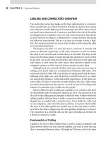
provides such a connection between a cable and a device. Because the media
used on a network can differ, a number of different connectors have been
developed over the years.
Twisted-Pair and Coaxial Cable Connectors
Several types of connectors are available for coaxial cable. Depending on the
need, connectors that connect to different cable and devices are available for
twisted-pair and coaxial. These include:
D connectors
RJ connectors
DIX connectors
BNC connectors
F-Type connectors
D Connectors
The D connector gets its name from its shape. As shown in Figure 2.2, with
some imagination, the D connector can be seen as looking like a letter D
turned on its side. A male connector is one that has pins protruding from it,
while a female connector has holes into which the pins fit. The number of
pins used in a D connector varies, but always correspond to the number used
in the D connector’s name. These include:
DB9, which has nine pins.
DB15, which has 15 pins, and we’ll discuss further in this chapter
when we examine DIX connectors.
DB25, which has 25 pins.
RJ Connectors
RJ connectors are used with twisted-pair cabling and can be used to provide
connectivity to a cable used by telephone and data devices. Because they are
used for different purposes, there are several different variations of RJ con-
nectors available.
rJ-11
RJ-11 connectors are used on twisted-
pair cables that are used by tele-
phones. You can easily find an RJ-11
connector in your home by looking
at the ends of the cable running from
FIGURE 2.2 DB15 Connector.
Connectors 77
your phone into the wall jack. They are also used to plug dial-up modems
into the phone line so that computers can dial into the Internet or access
networks remotely using the phone line. They are primarily used in North
America and are not widely used in other countries throughout the world.
RJ-11 connectors have four pins to support four of the wires in a twisted-
pair cable. Although the connector can be used with different categories of
twisted-pair, only two pairs of wires are used, even if the cable contains more
than four wires.
rJ-45
The RJ-45 connector is used with twisted-pair cables that support data com-
munication. As such, they can be used with Categories 3 and higher of UTP
or STP cabling. They are commonly seen on today’s networks, as they are
used on both Ethernet and Token Ring networks.
An RJ-45 connector looks like a RJ-11 connector, but wider. RJ-45 con-
nectors are similar to the phone connectors except that instead of four wires
found in the home system, the network RJ-45 contains eight contacts. There
are eight pins in the connector; hence eight wires in the cable are connected
to it. Ethernet can use four of the wires or possibly all eight, depending on the
media standard being used. As we saw earlier in this chapter, a special crimp-
ing tool is needed to make contact between the pins and the cable inside.
rJ-48 and rJ-25
In addition to the RJ-11 and RJ-45 connectors that are used for voice and
data communication, there are also a number of other RJ connectors that
may be found in offices. The different types are used to provide different
services, but are all used with twisted-pair cabling.
RJ-48 connectors are essentially the same as the RJ-45 connector, but
used with STP cable. Like the RJ-45 connector, it uses eight pins to provide
contact with the eight wires in a twisted-pair cable, although a different pin
arrangement is used in connecting the wires.
Another example of a RJ is the RJ-25 connector. RJ-25 connectors use
six conductors to allow multiple phone lines to be used. They are often seen
when telephones have three line connections.
DIX
Earlier in this chapter we discussed D connectors and how they consist of
pins that are inserted into a female connector. One type of D connector is
a DIX, which is used with an AUI that’s used with 10Base5 cable. A DIX
connector looks similar to the connector used for attaching a joystick to a
joystick port. DIX connectors can be found on the back of some network
cards and allow the card to be used with different types of media.
ChApTEr 2: Network Media 78
BNC
The meaning of the acronym BNC is something that is a topic of debate. It is
commonly referred to as a British Naval Connector, but it is also referenced as
meaning Bayonet Neill Concelman or Bayonet Nut Connector. Regardless of
your preference, the BNC connector is used with coaxial cable.
If you’ve ever looked at the end of the cable used for your cable televi-
sion, you’ve seen one that looks similar to what’s illustrated in Figure 2.3.
The copper wire running down the center of the cable protrudes from the
center of a BNC barrel connector. The connector is threaded, allowing it to
be screwed onto devices with a corresponding connector, so that the wire can
fit into the female connection.
There are different variations of the BNC connector that can be used on
a network. BNC connectors are used to connect 10Base2 coaxial cable to
a hub, while a T-connector (Figure 2.4) can connect a workstation’s cable
segment to the network backbone. A special crimping tool is used to put the
connector on the end of the wire. The actual wire runs down the middle and
must make contact with the end of the connector shown in the middle.
EXERCISE 2.2 Terminating a Coaxial Cable
Now that you have learned about coaxial cable and how to identify it, we will
learn how to terminate a coaxial connector on to a RG type cable.
As with twisted-pair cable termination, you will need to use crimping 1.
and stripping tools when terminating a coaxial cable, although the
process itself is a little different. For one, you will need a stronger
cutter that is sized properly for the job of cutting thick coaxial cable.
FIGurE 2.3 BNC Barrel Connector.
FIGurE 2.4 BNC T-Connector.
Connectors 79
To terminate the cable, you will need a ratchet crimper, a pair of 2.
coaxial cable strippers, the coaxial cable itself, and BNC connectors.
Use the cable cutter to cut a length of coaxial cable from a bulk spool 3.
if you have one available. The cable should be the proper length for
the job, plus some extra slack for you to make some mistakes when
cutting your cable. Remember, never cut cable (especially preexisting
runs) without giving yourself a little extra cable to play with.
Next, use the cable stripper to remove the excess jacketing and 4.
outside coating of the cable.
Apply the RG-type connector on the cable and crimp it down.5.
Do both sides of the cable if not already done.6.
Make sure you test the cable and ensure that it is within specifications.7.
RG and F-Type Connectors
F-type connectors are used to terminate coaxial cable and are commonly
seen on RG-58 (Thinnet) and RG-59 (Thicknet) coaxial. Although it is an
older type of connector, it is still frequently used. These connectors have the
ability to screw onto televisions, VCRs, and devices for cable television, and
are low in cost.
Fiber Connectors
There are a number of different connectors that are used with fiber-optic
cable. As is the case with some of the connectors available for twisted-pair
and coaxial cable, some of these are used with older technology and are not
routinely seen on modern networks. They include:
Straight tip
Standard connector
Local connector
Mechanical transfer registered jack
Standard Connectors
SC stands for standard connector, and is a suitable name, as it’s the most com-
mon type of connector used with fiber-optic cable. It is often used with Cisco
equipment. As shown in Figure 2.5, the SC terminates the fiber-optic cable by
attaching to its end, using a locking mechanism that clicks into place.
CHAPTER 2: Network Media 80
ST Connectors
ST connectors are an older version of connector used on fiber-optic cable. It
is often seen on older 10BaseFL networks. The ST connector has a screw-on
type of locking mechanism that attaches to the tip of a fiber-optic cable and
terminates it. In using this type of connector (shown in Figure 2.6), you will
find that it has the look and feel of a BNC connector, making it easy to use.
Local Connectors
The LC is another common connector used on fiber-optic networks. LC is a
high-performance connector that is used on many networks. LC connectors
use a locking mechanism that’s similar to the SC, which click into place. The
connector is seated into place by pushing it in and snapping it into place.
FIGURE 2.5 SC Connector.
FIGURE 2.6 ST Connector.
Exam Warning
An easy way to remember the SC is by thinking of its name (standard connector), which
indicates that it’s the most common one used today. An alternative method of remember-
ing it is to think of SC as stick and click. This will help you to remember that it uses a
click-into-place locking mechanism.
Exam Warning
An easy way to remember the characteristics of an ST connector is by using its nickname
stick and twist. This will help you to remember that it is a screw-on type of connector, as
you stick and twist it on.
Exam Warning
An easy way to remember the characteristics of an LC connector is by thinking of the
term lock and click. This will help you to remember that its locking mechanism requires
you to push and click it into place.
81Recognizing Category 3, 5, 5e, and 6 UTP
Mechanical Transfer Registered
Jacks
The MTRJ is similar to the LC con-
nector in that it is a duplex con-
nector. As shown in Figure 2.7, it
uses a form factor and latch that is
similar to the RJ-45 connectors dis-
cussed earlier in this chapter. It is
also easier to terminate and install
than some of the other types of fiber-optic connectors we’ve discussed,
such as the ST and SC connectors.
RECOGNIZING CATEGORY 3, 5, 5E, AND 6 UTP, STP,
COAXIAL CABLE, SMF OPTICS CABLE, MMF OPTIC
CABLE, AND OPTIC CABLE
Although we’ve already provided you with a lot of information about
cabling and their respective issues, it’s time to go in depth into the types
of cabling you’ll find on networks and the Network exam. As we’ve
discussed, there are three types of physical media that can be used on
a network: coaxial cable, twisted-pair cable, and fiber-optic cable. These
different media types can be further broken down into different categories
and types of cabling, which are either used for specific purposes or provide
greater bandwidth.
Category 3, 5, 5e, and 6 UTP
UTP cabling is the most common type of physical media on networks today.
The typical twisted-pair cable for network use contains three or four pairs
of wires. As shown in Figure 2.8, each pair of wires contained in the cable
is twisted around each other, which helps shield against crosstalk and other
forms of EMI. Although the twisted wires do provide a certain amount of
immunity from the infiltration of unwanted interference, this doesn’t mean
that UTP is the best solution against EMI. Twisted-pair cable is susceptible
to interference and should not be used in environments containing large
electrical or electronic devices.
Because UTP is used for everything from telephone cable to high-
speed network cable, the Electrical Industry Association established
different categories of UTP. These categories are rated by a number of
factors, including the electrical characteristics, conductor size, and twists
FIGURE 2.7 MTRJ Connector.
CHAPTER 2: Network Media 82
per foot. Because new categories are
also an indication of enhancements
in the wiring, the higher categories
are also new evolutions of twisted-
pair. The various categories, which
are simply referred to as CAT, are
shown in Table 2.6.
Table 2.6
Categories of Twisted-Pair Cabling
Category Uses
CAT 1 Up to 1 Mbps. Voice communication in older analog telephone systems
and also used as doorbell wiring. This type of cabling is not suitable for data
transmissions.
CAT 2 4 Mbps. Low performance cable; used for voice and low-speed data
transmission.
CAT 3 16 Mbps. Voice communication in newer telephone systems. Rated at
10 MHz, this is the minimum category of UTP that can be used for data
transmissions on networks; can be used for Ethernet, Fast Ethernet, and
Token Ring.
CAT 4 20 Mbps. Used for data and voice transmission; rated at 20 MHz; can be
used for Ethernet, Fast Ethernet, and Token Ring.
CAT 5 100 Mbps (4 pairs). Typically used for Ethernet networks running at 10 or
100 Mbps. Used for data and voice transmission; rated at 100 MHz; suitable
for Ethernet, Fast Ethernet, Gigabit Ethernet, Token Ring, and 155 Mbps
ATM.
CAT 5e 1000 Mbps. Recommended for all new installations and was designed
for transmission speeds of up to 1 Gbps (Gigabit Ethernet). Similar to
Category 5, but manufacturing process is refined; higher grade cable than
Category 5; rated at 200 MHz; suitable for Ethernet, Fast Ethernet, Gigabit
Ethernet, Token Ring, and 155 Mbps ATM.
CAT 6 Same as CAT5e, but higher standard. Rated at 250 MHz; suitable for
Ethernet, Fast Ethernet, Gigabit Ethernet, Token Ring, and 155 Mbps ATM.
CAT 6e Support for 10 Gigabit Ethernet. Similar to Category 6, but is a proposed
international standard to be included in ISO/IEC 11801.
CAT 7 Not official standard at time of this writing. Still in development. Rated at
600 MHz; suitable for Ethernet, Fast Ethernet, Gigabit Ethernet, Token Ring,
and 155 Mbps ATM.
FIGURE 2.8 Unshielded Twisted-Pair.
Test Day Tip
Although there are a number of different categories of UTP, the Network exam expects
you to know the details of CAT 3, 5, 5e, and 6 cables. You should only review the other
categories to know what is being offered as incorrect choices.
83Recognizing Category 3, 5, 5e, and 6 UTP
Category 3 is the minimum grade of cable that supports networking,
but it is not the best choice for networks. CAT3 is a voice-grade cable used
in phone networks, and its only real benefit beyond being able to sup-
port data communication is that it already exists in most office buildings
and homes. Regardless of this, CAT 5 or higher should be used in new
networks.
Most of the UTP cable that’s found in networks today is Category 5. CAT
5 is a multipair performance cable with eight wires (four pairs) that supports
higher bandwidth and is typically used for Ethernet networks that run at
10 or 100 Mbps. Until recent enhancements were made to UTP, this grade
of cabling was the standard for new network installations.
Category 5e is essentially the same as CAT 5 cable, but adheres to more
stringent standards that make it as a better candidate for new installations
that will use Gigabit Ethernet. It is designed for transmission speeds of up to
1 Gbps and has been made an official standard.
Category 6 is another enhancement to the previous grades and provides
support for 10 Gigabit Ethernet. It is officially a part of the 568A standard,
making it a standard grade of cable for UTP installations.
STP
As its name says, the difference between the unshielded and shielded variet-
ies of twisted-pair is the shield. As shown in Figure 2.9, STP has a shield
that’s usually made of aluminum/polyester that resides between the outer
jacket and the wires. The shield is designed to keep more interference out,
protecting the wires inside from EMI caused by outside sources. STP also
uses a much higher quality protective jacket for greater insulation.
Coaxial Cable
Coaxial (or coax) cable looks like
the cable used to bring the cable
TV signal to our television. As
shown in Figure 2.10, one strand
(a solid-core wire) runs down the
middle of the cable. Around that
Exam Warning
Category 1 and 2 of UTP is for voice communications. Category 3 or higher can be used
for data communications, but Category 5 or higher should be used. On the exam, you
may see these categories abbreviated, so that they use the term CAT for category. Don’t
let this confuse you.
Plastic Covering
Shielding Copper
Wire
Insulation
FIGURE 2.9 Shielded Twisted-Pair.
CHAPTER 2: Network Media 84
strand is insulation. Covering
that insulation is braided wire and
metal foil, which shields against
EMI. A final layer of insulation
covers the braided wire. Coaxial
cable is resistant to the interference
and signal weakening that other
cabling, such as UTP cable, can
experience. In general, coax is bet-
ter than UTP cable at connecting
longer distances and for reliably supporting higher data rates with less
sophisticated equipment.
Just because the TV cable is coax does not mean it will work with com-
puter networks. Network coaxial cable has very specific requirements, such
as the gauge, the impedance, and the attenuation.
Thinnet refers to RG-58 cabling, which is a flexible coaxial cable about
1/4 inch thick. Thinnet is used for short-distance communication and is
flexible enough to facilitate routing between workstations. Thinnet connects
directly to a workstation’s network adapter card using a BNC T-connector
and uses the network adapter card’s internal transceiver. 10Base2 refers to
Ethernet LANs that use Thinnet cabling.
Thicknet coaxial cable can support data transfer over longer distances
better than Thinnet can and is usually used as a backbone to connect
several smaller Thinnet-based networks. The diameter of a Thicknet
cable is about 1/2 inch and is harder to work with than a Thinnet cable.
A transceiver is connected directly to Thicknet cable using a connector
known as a piercing tap. Connection from the transceiver to the network
adapter card is made using a drop cable to connect to the adapter unit
interface port connector. 10Base5 refers to Ethernet LANs that use Thick-
net cabling.
SMF-Optic Cable
Optical fibers carry digital data signals in the form of modulated pulses of
light. As shown in Figure 2.11, an optical fiber consists of an extremely
thin cylinder of glass or optical fiber, called the core, surrounded by a
concentric layer of glass, known as the cladding. A cable may contain
FIGURE 2.10 Coaxial Cable.
Exam Warning
Although coax is not as commonly used as it used to be, the Network exam expects you
to understand what it is and how it works. You will need to understand the lengths of cabling
that can be used with Thinnet and Thicknet coax as well as the transmission speeds.
Other Media 85
two fibers per cable – one to trans-
mit and one to receive – or a single
fiber. However, often, multiple fibers
are bundled into the center of the
cable. The fiber and cladding can
be surrounded by a liquid gel that
reflects signals back into the fiber to
reduce signal lost, or a plastic spacer
surrounded by Kevlar fiber. Each of
these components making up the
fiber-optic cable is further protected
by a plastic covering that encases
everything within the cable.
There are two different types of
fiber-optic cabling that may be used
to carry data: SMF and MMF. SMF is
optical fiber that’s designed to trans-
mit a single beam of light from a laser.
The beam of modulated light provides
greater bandwidth and allows cable to
be run over longer distances. Because
of these features, SMF is used for long
distance transmissions such as in tele-
phone and cable television networks.
MMF-Optic Cable
MMF is used to carry multiple beams of light at the same time, using
a light emitting diode (LED) as a light source. Each of the beams is at a
slightly different reflection angle within the core of the fiber. Because the
light tends to disperse over distance, MMF is used for connecting locations
within relatively short distances.
OTHER MEDIA
Although the cabling, connectors, and other elements of a network we’ve
discussed in this chapter are either traditional components of a network, or
have grown to become standard, there are other technologies that are either
new, not readily associated with networking, or often forgotten. Nevertheless,
elements such as wireless technologies, FireWire, and transceivers are impor-
tant to networking. Such media is not only covered on the Network exam,
but it is important to the design or development of your network.
FIGURE 2.11 Fiber-Optic Cabling.