CompTIA Network+ Certification Study Guide part 12 pps
Bạn đang xem bản rút gọn của tài liệu. Xem và tải ngay bản đầy đủ của tài liệu tại đây (257.96 KB, 10 trang )
CHAPTER 2: Network Media 96
C. Use 10BaseT cabling in each of the buildings, and connect the
two buildings together using 10Base5 cabling.
D. Use 100BaseFX cabling in each of the buildings, and connect the
two buildings together using 10BaseT cabling.
Your network uses 100BaseFX so that data can be transferred at 9.
higher speeds and up to distances of 400 m. During transmission,
data can travel in both directions, but only in one direction at a
given time. Which of the following transmission methods is used?
A. Simplex
B. FireWire
C. Half-Duplex
D. Full Duplex
Examine the illustration shown in Figure 2.13. Your network uses 10.
UTP cabling in a star topology. Which of the following types of
connectors is being used?
A. RJ-45
B. BNC
C. ST
D. SC
You are the Network11. technician assigned to an enterprise
network looking to install a high-speed backbone. You want to
implement Gigabit Ethernet. Which connectors could you use in
such a network? (Choose one.)
FIGURE 2.13
Self Test 97
A. RJ-11
B. RG 58
C. SC
D. BNC
As a Network technician for 123 LLC, you are asked by your 12.
CIO about the access method of Gigabit Ethernet. Which of the
following access methods does Gigabit Ethernet use?
A. FDDI
B. CSMA/CD
C. CSMA/CA
D. Token passing
A new technician for 123 Corp plans out the maximum length of a 13.
Gigabit Ethernet segment using MMF optic cable is. What is the cor-
rect distance? (Choose only one)
A. 100 m
B. 125 m
C. 550 m
D. 10 km
You are the network engineer assigned to implement a new 14.
100 Mbps network connection. You need to select the correct
cabling, as well as the correct standard. From the selections below,
choose which 100 Mbps networking standard makes use of only
two pairs of a Category 5 UTP cable.
A. 10BaseT
B. 100BaseFL
C. 100BaseTX
D. 100BroadT4
You work as a network technician for 123 LLC. You need to check 15.
the electrical signals being sent from the NIC port out on the cable.
Which device would you use to complete this test? (Choose one.)
A. A wire map
B. A fox and hound
C. A crossover cable
D. A hardware loopback
CHAPTER 2: Network Media 98
SELF TEST QUICK ANSWER KEY
B1.
A2.
B3.
D4.
B5.
B6.
D7.
C8.
C9.
A10.
C11.
B12.
C13.
C14.
D15.
99
CHAPTER 3
EXAM OBJECTIVES IN THIS CHAPTER
NETWORK DEVICES 99
INTRODUCTION
A network is composed of many different devices; some perform a single
function and others perform a variety of functions, from routing data to
applying security filters. As networking devices become more complex, they
also become more versatile, in that they may be able to perform multiple roles
that previously could only be carried out by individual devices. Some network
devices are complex enough to warrant their own operating systems for inten-
sive and detailed configuration. In some cases, these operating systems can
be switched out, substituted, or used to configure the device to perform roles
traditionally carried out by other devices. For example, a Layer 3 switch might
be configured to combine both switching and routing functions. This coming
together of technology within one device is called convergence.
In this chapter we will briefly discuss convergence, and we will look at the
most common network devices in use today on small and large networks,
including the Internet. These devices range from the very simple (such as
an active hub, which simply repeats and sends out signals to all ports) to the
more complex devices, such as a firewall, which is responsible for controlling
traffic and applying security features.
NETWORK DEVICES
Network devices are components of a network that are required if the
network is to grow, function, or provide certain functionality. There are a
number of devices that fall into this category, including routers, switches,
Network Devices
CHAPTER 3: Network Devices 100
and other devices that we’ve mentioned briefly in previous chapters. These
network devices provide functionality such as connectivity to physical
media, security features, and the ability to connect to resources outside
of the local area network (LAN). Before we discuss the current state of
networking and the available devices, let’s take a look at how the current
devices evolved.
Historical Network Devices
As we discussed in Chapter 1, networks have been around for decades, so
it follows that some devices have been around longer than others. As we’ll
see in the sections that follow, although some devices are as useful today as
when they were initially introduced, others have become obsolete and are
rarely used on today’s networks. In discussing these devices, we’ll tell you
about their purpose, features, and functions on a network.
HEAD OF THE CLASS…
OSI and Network Devices
Network devices can be mapped to the Open Systems
Interconnect (OSI) networking model. OSI is a group
of standards that provides a logical structure for net-
work operations and contains seven layers, which from
the highest to lowest are as follows: application, pre-
sentation, session, transport, network, data link, and
physical.
Network communication starts at the applica-
tion layer of the OSI model and works its way down
through the layers step by step to the physical layer.
The information then passes along the cable to the
receiving computer, which starts the information at
the physical layer. From there it steps back up the
OSI layers to the application layer where the receiving
computer finalizes the processing and sends back an
acknowledgement if needed. Then the whole process
starts over.
Table 3.1 shows the devices mapped to the OSI
layers at which they operate.
Table 3.1
Mapping of Network Devices to the OSI Model
OSI Layer Devices
Application Gateway
Presentation Gateway
Session Gateway
Transport Gateway
Network Router, multilayer or Layer 3 switches, gateway
Data Link NIC, bridge, Layer 2 switches, access point, gateway
Physical Hub, MAU, repeater, gateway
Network Devices 101
Hubs
Although hubs have been around since the early days of networking, they
continue to be one of the most commonly used connection-based net-
work components. Especially now that home networks are growing and
more small office home offices (SOHOs) are emerging, hubs are becom-
ing a common household item. Some homes are even built with a plan
for a centralized wiring system, Internet access, routers, and hubs all
included.
Hubs are predecessors of switches, which we’ll discuss later in this
chapter, and are central locations for connecting network cabling. Multi-
ple cables connect into the hub, providing a method for data to be passed
from one cable to another. This is also why switches are sometimes
referred to as switching hubs, though that terminology is not commonly
used today.
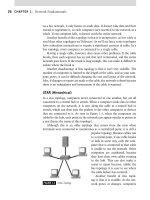
As we discussed in Chapter 1, a star topology uses a hub to connect
workstations, servers, and other devices. As shown in Figure 3.1, you can
easily remember the layout of a hub if you think of a wheel and picture
how the spokes go to the hub of the wheel. Each spoke is a connection and
the hub of the wheel is the hub of the network where all the cables come
together. Because all of the connections concentrate in the center, the hub
is also called a concentrator.
Each of the cables that extends to the hub from computers and other
network devices is plugged into its own port on the hub. The port pro-
vides an interface between the cable and the hub. For example, because
star topologies may use unshielded twisted-pair (UTP) cable, UTP is
a common cable type that is used with hubs. The RJ-45 connector of
the cable is plugged into a port on
the hub. When data is sent from
a computer, it is carried along the
cable to the port that the RJ-45
connector is plugged into. The hub
then takes this data and passes it to
the other ports, allowing the data
to travel along the other cables to
workstations and devices that are
attached to it. The number of ports
on a hub will vary, but generally
four or more are provided. Many
hubs provide 24 or 28 ports and
can be attached together (or more
commonly referred to as uplinked
FIGURE 3.1 Hubs Are Used in Star Topologies.
CHAPTER 3: Network Devices 102
or cascaded together) to provide connectivity to even more computers or
network devices. There are rules, of course; when working with hubs, you
should always apply the 5-4-3 rule, which states that you can only con-
nect a total of 5 segments linked together via 4 hubs and only 3 of those
segments can be populated with network hosts such as PCs or printers.
Breaking rules of this kind could lead to a degradation of performance and
possible problems.
The two main types of hubs are passive and active. A switching hub is
actually a type of switch that behaves like a hub.
Passive Hubs
In discussing hubs to this point, we have essentially been talking about pas-
sive hubs. A passive hub provides basic features of moving data from one
port to another. Its function is simply to receive data from one port of the
hub and send it out to the other ports. For example, an 8-port hub receives
data from port 3 and then resends that data to ports 1, 2, 4, 5, 6, 7, and 8.
It is as simple as that.
A passive hub contains no power source or electrical components. There
is no signal processing. It simply attaches the ports internally and enables
communication to flow through the network.
Active Hubs
An active hub provides the same functionality that a passive hub does, with
an additional feature. Active hubs repeat (regenerate) the data while resend-
ing it to all of its ports. By using active hubs you can increase the length of
your network beyond regular cable length limits. For example, UTP Category
5 cabling can be run a maximum of 100 m. With an active hub, you can run
Category 5 UTP 100 m on each side of the hub so that your cable now runs
a length of 200 m in total.
Exam Warning
Hubs broadcast traffic on every single port. Because hubs only operate at the physi-
cal layer, they are deemed unintelligent. A hub is simple by design; a signal comes in
from a connected PC, and the hub just sends that signal out to every port that it knows.
For example, suppose an 8-port hub has eight PCs attached. If PC 1 sends an e-mail
to PC 2, that transmission will go to all the eight PCs. The data, of course, will get to
its destination, but all six of the uninvolved PCs are interrupted because each has to
examine the data to determine if it is the recipient. This process takes time, and if you
multiply this over the traffic of a normal large-scale enterprise network, it’s easy to see
why hubs are typically limited to small networks.
Network Devices 103
An active hub has a power source and built-in repeaters to boost the
signal. There are extra electronics built into an active hub that allow for
signal regeneration, which is how the incoming data on one port is repeated
to the other ports. Because the signal is repeated in this way to the other
ports, an active hub is also called a multiport repeater.
Switching Hubs
Although active and passive hubs will pass data to every other port on the
hub, a switching hub will only send data to its intended port. Switching hubs
are also referred to as intelligent hubs, as they can determine which port will
get the data to its proper destination. The fact is, however, that even though
it is referred to as a switching hub, these are the features of another device
called a switch (which we’ll discuss later in this chapter). Although this term
may be used in the real world to refer to a switch, for the Network+ exam
it’s best to keep the components separate in your mind. A switch is a switch,
and a hub is a hub.
Repeaters
A repeater is a device that is rarely seen on networks today, as its features are
typically incorporated into other devices, such as active and switching hubs.
The repeater will take a signal that may be weakening and regenerate it to its
original strength. In doing so, it actually recreates the signal, making it the
same strength that it was when it left the sending workstation.
To help you understand a repeater, imagine that you are with a friend and
both of you are standing at opposite ends of a street. If you shouted some-
thing to your friend, the sound would fade over a distance. If someone stood
between the two of you, however, and repeated your message, then it would
be repeated strong and loud, allowing your friend to hear it. A repeater works
Test Day Tip
The Network+ exam includes questions that deal with active hubs. Passive hubs
aren’t covered on the current version of the exam. This information is included for
completeness.
Exam Warning
Hubs operate at the physical layer of the OSI model (also known as Layer 1). Hubs are
designed to simply forward data from one port of the hub to another, so they don’t use
upper-layer protocols such as Internet Protocol (IP), Internetwork Packet Exchange (IPX),
or Media Access Control (MAC) addressing to ensure that the data reaches its intended
destination.
CHAPTER 3: Network Devices 104
in a similar fashion by repeating the data so it’s in its original, strong form
preventing corruption as it weakens over distance.
Historically, repeaters were first created to fix a problem. Cables had
length limitations, which were solved by connecting a repeater to two cable
segments to extend the range beyond the regular distance limit. Repeaters
were commonly used on Ethernet networks, such as those using UTP or
coaxial cable, and provided networks with the ability to extend cable seg-
ments. 10BaseT limitations are 100 m or approximately 328 feet. Thickwire
(also known as 10Base5 or Thicknet) can normally transmit a distance of
500 m, whereas thinwire (also known as 10Base2 or Thinnet) can normally
transmit a distance of 185 m. By putting a repeater between these segments,
the distance that data can travel can be doubled. Remember, when using
repeaters, greater lengths of cabling were allowed when planning a cabling
scheme.
Bridges
A bridge is a network connectivity device that connects two different net-
works and makes them appear to be one network. It can connect two differ-
ent LANs, or allow a larger LAN to be segmented into two smaller halves.
The bridge filters local traffic between the two networks and copies all other
traffic to the other side of the bridge.
Bridges are intelligent devices and have the ability to forward packets
of data based on MAC addresses. A bridge can look at a packet of data and
determine the source and destination involved in the transfer of packets. It
will read the specific physical address of a packet on one network segment
and then decide to filter out the packet or forward it to another segment.
A bridge is another device that has largely become a thing of the past.
Although bridges were a common component of older networks, their fea-
tures are now typically incorporated into switches. One benefit of a switch
over a bridge is that a bridge only has two ports typically, one for each seg-
ment that it is connecting. Switches may have many ports, and as we’ve
already seen, incorporate features that were previously found in other
devices, such as hubs.
Note
Unlike previous versions of the Network+ exam, repeaters are no longer directly tested
on the exam. The function of a repeater is to regenerate data so that it can be passed
further than the maximum distance of a cable segment. The ability to regenerate data
and perform this function is now found incorporated in other network devices, such as
hubs and switches.
Network Devices 105
Network Segmentation
A bridge is a simple way to accomplish network segmentation. Placing a
bridge between two different segments of the network decreases the amount
of traffic on each of the local networks. Although this does accomplish
network segmentation, most network administrators opt to use routers or
switches, which are discussed later in the chapter.
Bridges segment the network by MAC addresses. When one of the work-
stations connected to one network has to transmit a packet, the packet is
copied across the bridge as long as the packet’s destination is not on its origi-
nating network segment. A bridge uses a bridging table to calculate which
MAC addresses are on which network. The MAC address uniquely identifies
computers and other devices on a network, just as the full address of your
house uniquely identifies its location.
Multistation Access Units
Multistation access units (also known as MAUs or MSAUs) are used to
connect workstations on a Token Ring network. Sometimes, an MAU is
referred to as a hub on the Network+ exam, but it shouldn’t be confused
with the active and passive hubs we discussed earlier, which are used on
Ethernet networks. The features of an MAU are different from those of a
standard hub.
An MAU typically has eight or more ports that provide connections
for workstations and other network devices on a Token Ring network. It
is also generally nonpowered, although some have been produced that are
powered with lights to indicate connectivity and activity. An MAU is not
something you will commonly find on newer networks simply because
newer networks generally are installed as Ethernet, more typically Fast
Ethernet or Gigabit Ethernet. MAUs are used with Token Ring networks,
which are present in today’s environments, but are not as prevalent as
Ethernet.
Test Day Tip
The Network+ exam frequently uses the term bridging and does refer to the actual
device quite often. Make sure that you understand the concepts of bridging that it will
connect up to two different network segments.
Exam Warning
Bridges operate at the data link layer of the OSI model and use physical addressing to
join several networks into a single network efficiently.