CompTIA Network+ Certification Study Guide part 13 pot
Bạn đang xem bản rút gọn của tài liệu. Xem và tải ngay bản đầy đủ của tài liệu tại đây (120.28 KB, 10 trang )
CHAPTER 3: Network Devices 106
HEAD OF THE CLASS…
What Do I Need to Know About Token Ring
for the Network+ Exam?
Although an aging technology, Token Ring is still sup-
ported on a great many networks. The reason is that
the mainframes used to be the rulers of the world and
many companies relied on them to store their data.
They were accessed by dumb terminals that ran on
UNIX. Many of those older networks ran Token Ring.
As dumb terminals were replaced by PCs and the
networks were migrated to Ethernet, the mainframes
stood firmly in place. What some may not know is
that because it was so expensive to replace a network
card on a mainframe, it was often cheaper to just get
a router with a Token Ring interface as well as an
Ethernet one, so many Token Ring networks exist as
of this day!
So what exactly do you need to know about Token
Ring? Well, it is important to know what it is not …
Ethernet. Do not let questions trip you up. You could
be asked about which type of hardware is used to
connect your networking interface card (NIC) to your
PC and MAU on an Ethernet network … Token Ring
and Ethernet hardware are completely incompatible;
they are completely two different standards. You would
need some form of gateway to translate one technol-
ogy to another, for example, as in the scenario men-
tioned earlier when the router was used to connect the
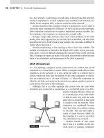
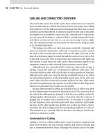
two dissimilar networks together. Figure 3.2 shows an
example of this in action.
In our example, the Windows Server system has
two NICs installed: one Ethernet, one Token Ring. The
Routing and Remote Access Service (RRAS) is installed
and functioning. This server is acting as a router and
connecting two different network segments together.
The Token Ring NIC is connected to an MAU with
two PCs attached to it. The Ethernet NIC is connected
to a hub with two PCs also connected to it. Although
both technologies coexist, do not think that they are
interchangeable – they are not. Ethernet is Ethernet,
and Token Ring is Token Ring. Be careful.
FIGURE 3.2 Two Networking Technologies Connected via a Windows Server 2008 Router.
Network Devices 107
Concepts of Convergence
Over the years, a number of network devices have become obsolete or less nec-
essary to a network because other devices have taken on their roles. Vendors
will attempt to put as many features as possible into a device, and they will
even include functions that other devices provide. As we discussed earlier
in this chapter, repeaters are no longer used on networks because switches
provide the same functionality. The same will apply to other devices used on
a home or office network. For example, a router used for Internet access may
include a switch for networking devices together, a firewall, and perhaps even
a wireless access point (WAP). As time goes on, you can expect to see other
devices converging together, requiring networks to have fewer components.
When taking the Network+ exam, it is wise to consider such devices as
separate, rather than as one device providing all features. For example, although
your router for the Internet has a firewall, you should consider a router and a
firewall as two separate components of a network when taking the exam.
The Modem and Other Adapters
Over the past decade, having access to the Internet and remote access to
networks has become as commonplace a method of communication as using
a telephone. People have come to expect to be able to get the information
they need quickly, and to be able to send messages and acquire data using a
modem or other adapter. In the sections that follow, we’ll look at a number
of devices used for such access, and discuss related topics that may appear
on the Network exam.
The modem gets its name from a combination of the terms modula-
tor and demodulator. In addition to analog modems, which typically pro-
vide connection speeds of up to 56 Kbps, there are other types of modems
that provide higher speed connections. These include digital subscriber line
(DSL) modems, cable modems, and Integrated Services Digital Network
(ISDN) adapters. In the sections that follow, we’ll discuss each of these types
of modems in greater detail.
Although there are many different types and makes of modems, they can
be categorized into three areas: single external, single internal, and multiline
rack or shelf mounted.
The external modem is commonly used to provide connectivity between
computers, existing as a separate component that is attached to a computer
using a cable. Many Internet service providers (ISPs) use pools of external
modems to enable dial-in access. They are also common in server hardware, as
many Information Technology (IT) personnel include modems in production
systems to allow for a backup communications link or for remote access.
CHAPTER 3: Network Devices 108
The internal modem performs the same functions as the external
modem. The only real difference is that it is located inside the computer
chassis. Although they are common in home computers, many companies
don’t use internal modems because external modems are easier to replace
and troubleshoot. For example, internal modems do not have the light emit-
ting diodes (LEDs) that external modems have. This translates into a head-
ache if you have to figure out why the modem won’t connect to a remote
host via the dial-up connection. Some modem manufacturers provide soft-
ware interfaces; however, these generally are not as full featured as for the
external modem.
Although internal modems are often adapter cards that are installed in
desktop computers, another type of internal modem is used in laptop com-
puters. Many laptop vendors integrate phone jacks into the chassis of the
computer, allowing a connection to an internal modem inside the laptop.
However, PC cards used with laptop computers can also be technically clas-
sified as an internal modem. The PC card bus, formerly known as PCMCIA,
is an architecture designed primarily for laptops and other portable comput-
ers. Adapters for this bus are sometimes called credit card adapters after their
size and shape, which is roughly equal to that of a credit card. Because of
their small size, most have a receptacle to which an external adapter must be
connected for attachment to the media. These modems are also sometimes
combined with an NIC in a single card called a combo card.
Many vendors also offer a solution that is a single chassis containing a
certain number of modem cards that can be connected directly to the net-
work. Its modularity and its size are much more efficient than trying to
maintain a shelf with a stack of external modems sitting on it. These have
also been included in some new networking equipment. Manufacturers place
analog modems in their equipment to facilitate redundancy features such as
a backup network link.
Analog Modems
An analog modem is a communications device that enables a computer to
talk to another computer through a standard telephone line. It does this
by converting digital data from the computer to analog data for transmis-
sion over the telephone line and then back to digital data for the receiving
computer. This is necessary because the public switched telephone network
(PSTN) uses analog waves to transmit voice communications, whereas com-
puters use digital data.
Because standard analog modems use a standard telephone line to acquire
connectivity to the Internet or a remote network, they use the same type of
cable that’s used by telephones. This type of cable uses an RJ-11 connector,
Network Devices 109
allowing the device to dial out using the same system that you use to make
telephone calls.
DSL and Cable Modems
Although modems that dial-up the phone number of an ISP or a computer
network have been around for many years, new kinds of modems have gained
popularity in recent years. Cable modems and DSL modems access tech-
nology that provides connection speeds in the megabit per second (Mbps)
range.
Cable modems are used to access the Internet using the broadband tech-
nology of cable television lines. The cable modem is similar to an analog
modem in that it translates data into a form that can be transmitted, and
retranslates it into data the computer can understand. When data is sent
using cable modems, the modem translates it into a coaxial-based technol-
ogy, which is used to split Internet access from television signals. Regardless
of the medium used, however, the basic purpose of the modem remains the
same – to allow you to access the Internet or remote networks.
The transmission speeds of a cable modem are typically as high as
1.544 Mbps. Although broadband Internet can provide greater speeds, allow-
ing a download path of up to 27 Mbps, the cable service provider is generally
connected to the Internet using a T1 line, which provides speeds of up to
1.544 Mbps.
Cable modems provide a constant connection to the cable service pro-
vider that also acts in the role of an ISP. The cable modem communicates
with a cable modem termination system (CMTS) provided by the cable ser-
vice provider, but it doesn’t have the ability to directly access other cable
modems. This is different from dial-up modems, which have the ability to
dial directly into other computers.
Another type of modem uses a technology called DSL. With DSL, your
local telephone company plays the role of ISP, providing access to the Inter-
net through the twisted-pair cabling of your phone line. Unlike a standard
modem that dials into an ISP over a telephone line, DSL allows simultane-
ous voice and data communication. In other words, you can surf the Web
and talk on the phone at the same time.
Although an analog modem converts digital data to an analog wave,
DSL transmits and receives data digitally across the phone line’s twisted-
pair cable. Because data isn’t converted, a higher bandwidth is available to
transfer the data. DSL typically provides transmission speeds of 1.544 Mbps,
although it can provide data transfer rates of up to 6.1 Mbps. The speed of
DSL does, however, decrease the further you are from a telephone company’s
offices or a repeater that regenerates the signal, because data rates decrease
CHAPTER 3: Network Devices 110
as they travel over cabling. The closer you are to the telephone company’s
offices, the faster your DSL connection will be.
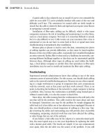
There are several different variations of DSL available (Table 3.2), which
offer different data transfer rates and distance limitations.
ISDN Adapters
ISDN is a system of digital telephone connections that enables data to be
transmitted simultaneously end to end. This technology has been available
for more than a decade, and before DSL and cable modems, ISDN was an
optimal choice for faster, clearer data communication. It came about as the
standard telephone system began its migration from an analog format to
digital.
History of ISDN
In the 1950s, the phone companies began looking at ways to improve com-
munications. They began by sampling the analog signals that were passed
during a phone conversation and attempted to convert them to digital
Table 3.2
Types of DSL
Type of DSL Bandwidth Distance Limitations
Asymmetric digital
subscriber line (ADSL)
Downstream: 1.544 to
6.1 Mbps. upstream: 16 to
640 Kbps
Speeds decrease over distance.
1.544 Mbps at 18,000 feet,
2.048 Mbps at 16,000 feet,
6.312 Mbps at 12,000 feet, and
8.448 Mbps at 9000 feet
Consumer digital
subscriber line (CDSL)
Downstream: 1 Mbps.
upstream: under 1 Mbps
18,000 feet
DSL lite or G. lite 1.544 to 6 Mbps 18,000 feet
ISDN digital subscriber
line (IDSL)
128 Kbps 18,000 feet
High digital subscriber
line (HDSL)
Varies depending on twisted
pair lines. 1.544 Mbps
duplex on two twisted-pair
lines, or 2.048 Mbps duplex
on three twisted-pair lines
12,000 feet
Symmetric digital
subscriber line (SDSL)
1.544 Mbps 12,000 feet
Very high digital
subscriber line (VDSL)
Downstream: 12.9 to
52.8 Mbps. upstream: 1.5 to
2.3 Mbps
Speeds decrease over distance.
4500 feet at 12.96 Mbps, 3000
feet at 25.82 Mbps, and 1000
feet at 51.84 Mbps
Network Devices 111
signals. From this analog sampling, they determined that 64 Kbps would
enable a digital signal to properly handle voice communications through the
telephone network. This became the foundation of ISDN.
Because a standard did not exist among the different phone companies,
the Consultative Committee for International Telephony and Telegraph
(CCITT) began working on the integrated digital network (IDN) in the late
1960s. IDN combined the functions of switching and transmission into one
piece of hardware that could be set as the standard for all telephone com-
panies to use. This initiative not only moved telephony services toward a
standard but also made the network much more efficient. It wasn’t perfect,
but it was a step in the right direction.
The concept of ISDN was introduced in 1972. The concept was based
upon moving the analog-to-digital conversion equipment onto the custom-
er’s premises to enable voice and data services to be sent through a single
line. Telephone companies also began using a new kind of digital commu-
nications link between each central office. A T1 link could carry 24 of these
64-Kbps voice channels, and it used the same amount of copper wire as only
two analog voice calls. Throughout the 1970s the telephone companies con-
tinued to upgrade their switching offices. They began rolling out T1 links
directly to customers to provide high-speed access. The need for an efficient
solution was greater than ever.
When ISDN was recognized by the International Telecommunications
Union (ITU), an initiative was begun to define its standards. The initial rec-
ommendations were published in CCITT Recommendation I.120 (1984) and
described some initial guidelines for implementing ISDN. In the early 1990s,
an effort was begun to establish a standard implementation for ISDN in the
United States. The NI-1 (National ISDN 1) standard was defined by the indus-
try so that the users would not have to know the type of switch they were con-
nected to in order to buy equipment and software compatible with it.
Because some major office switches were incompatible with this stan-
dard, some major telephone companies had trouble switching to the NI-1
standard. This caused some problems when trying to communicate between
these nonstandard systems and everyone else. Eventually, all of the systems
were brought up to standard. A set of core services was defined in all basic
rate interfaces (BRIs) of the NI-1 standard. The services include data call
services, voice call services, call forwarding, and call waiting. Most devices
today conform to the NI-1 standard.
A more comprehensive standardization initiative, NI-2 (National ISDN 2),
was adopted in recent years. Now, several major manufacturers of networking
equipment have become involved to help set the standard and make ISDN
a more economical solution. The NI-2 standard had two goals: standardize
CHAPTER 3: Network Devices 112
the primary rate interface (PRI) as NI-1 did for the BRI, and simplify the
identification process. Until this point, PRIs were mainly vendor dependent,
which made it difficult to interconnect them. Also, a standard was created
for NI-2 for identifiers.
ISDN Channels
An ISDN transmission circuit consists of a logical grouping of data channels.
With ISDN, voice and data are carried by these channels. Two types of chan-
nels are used for a single ISDN connection: a B channel and a D channel.
Each channel has a specific function and bandwidth associated with it. The
bearer channels (B channels) transfer data, and offer a bandwidth of 64 Kbps
per channel. A hardware limitation in some switches limits the B channels
to 56 Kbps, or 56,000 bytes.
The data channel (D channel) handles signaling at 16 or 64 Kbps. This
includes the session setup and teardown using a communications language
known as DSS1. The purpose of this channel is to enable the B channels to
strictly pass data. You remove the administrative overhead from them by
using the D channel. The bandwidth available for the D channel is dependent
upon the type of service – BRIs usually require 16 Kbps and PRIs use 64 Kbps.
Typically, ISDN service contains two B channels and a single D channel.
H channels are used to specify a number of B channels. The following list
shows the implementations:
H0 384 Kbps (6 B channels)
H10 1472 Kbps (23 B channels)
H11 1536 Kbps (24 B channels)
H12 1920 Kbps (30 B channels) – Europe
ISDN Interfaces
Although B channels and D channels can be combined in any number of ways,
the phone companies created two standard configurations. There are two basic
types of ISDN service: BRI and PRI. BRI consists of two 64-Kbps B channels
and one 16-Kbps D channel for a total of 144 Kbps. Only 128 Kbps is used for
user data transfers. BRIs were designed to enable customers to use their exist-
ing wiring. This provided a low-cost solution for customers and is why it is the
most basic type of service today intended for small business or home use.
PRI is intended for users with greater bandwidth requirements. It requires
T1 carriers to facilitate communications. Normally, the channel structure
contains 23 B channels plus one 64-Kbps D channel for a total of 1536 Kbps.
This standard is used only in North America and Japan. European countries
Network Devices 113
support a different kind of ISDN standard for PRI. It consists of 30 B channels
and one 64-Kbps D channel for a total of 1984 Kbps. A technology known as
nonfacility associated signaling (NFAS) is available to enable you to support
multiple PRI lines with one 64-Kbps D channel.
To use BRI services, you must subscribe to ISDN services through a local
telephone company or provider. By default, you must be within 18,000 feet
(about 3.4 miles) of the telephone company central office for BRI services.
Repeater devices are available for ISDN service to extend this distance, but
these devices can be very expensive. Special types of equipment are required
to communicate with the ISDN provider switch and with other ISDN
devices; you must have an ISDN terminal adapter and an ISDN router.
ISDN Devices
The ISDN standard refers to the devices that are required to connect the
end node to the network. Although some vendors provide devices that have
several functions included, a separate device defines each function within
the standard. The protocols that each device uses are also defined and are
associated with a specific letter. Also known as reference points, these letters
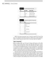
are R, S, T, and U. ISDN standards also define the device types. They are
NT1, NT2, TE1, TE2, and TA. The architecture for these devices and the
reference points, which we’ll discuss further in the next section, can be seen
in Figure 3.3.
ISDN Reference Points
Reference points are used to define logical interfaces. They are, in effect, a
type of protocol used in communications. The following list contains the
reference points:
R defines reference point between a TE2 device and a TA device.
S defines reference point between TE1 devices and NT1 or NT2 devices.
T defines reference point between NT1 and NT2 devices.
U defines reference point between NT1 devices and line
termination equipment. This is usually
the central switch.
Network Termination 1 (NT1) is the device
that communicates directly with the central
office (CO) switch. The NT1 receives a U inter-
face connection from the telephone company and
puts out a T interface connection for the NT2.
NT1 handles the physical layer portions of the
FIGURE 3.3 ISDN Device Architecture.
ISDN
Switch
U
S/ T
TE1
NT1
T
A
R
TE1
TE2
CHAPTER 3: Network Devices 114
connection, such as physical and electrical termination, line monitoring,
and multiplexing.
Network Termination 2 (NT2) is placed between an NT1 device and any
adapters or terminal equipment. Many devices provide the NT1 and NT2
devices in the same physical hardware. Larger installations generally sepa-
rate these devices. An example of an NT2 device is a digital Private Branch
eXchange (PBX) or ISDN network router. An NT2 device provides an S inter-
face and accepts a T interface from an NT1. NT2 usually handles data link
and network layer functions in network with multiple devices such as con-
tention monitoring and routing.
Terminal Equipment 1 (TE1) is a local device that speaks via an S inter-
face. It can be directly connected to the NT1 or NT2 devices. ISDN tele-
phones and ISDN fax machines are good examples of TE1 devices.
Terminal Equipment 2 (TE2) devices are common everyday devices that
can be used for ISDN connectivity. Any telecommunications device that is
not in the TE1 category is classified as a TE2 device. A terminal adapter is
used to connect these devices to an ISDN network and attaches through an
R interface. Examples of TE2 devices include standard fax machines, PCs,
and regular telephones.
A terminal adapter (TA) connects TE2 devices to an ISDN network. It
connects through the R interface to the TE2 device and through the S inter-
face to the ISDN network. The peripheral required for personal computers
often includes an NT1 device. These are better known as ISDN modems.
Identifiers
Standard telephone lines use a 10-digit identifier that is permanently
assigned. This is the telephone number. ISDN uses similar types of identi-
fiers; however, they are not as easily used as a telephone number. ISDN
uses five separate identifiers when making a connection. The provider
assigns two of these when the connection is first set up: the service pro-
file identifier (SPID) and the directory number (DN). These are the most
common numbers used because the other three are dynamically set up
each time a connection is made. The three dynamic identifiers are termi-
nal endpoint identifier (TEI), bearer code (BC), and service access point
identifier (SAPI).
The SPID is the most important number needed when using ISDN. The
provider statically assigns this number when the ISDN service is set up.
It usually includes the directory number plus a few extra digits. The SPID
usually contains between 10 and 14 characters and varies from region to
region. SPIDs can be assigned for every ISDN device, for the entire line, or
for each B channel.
Network Devices 115
The SPID is unique throughout the entire switch and must be set up
correctly. If it is incorrect, it is like dialing the wrong phone number – you
will not be able to contact the person you are trying to reach. When an ISDN
device is connected to the network, it sends the SPID to the switch. If the
SPID is correct, the switch uses the stored information about your service
profile to set up the data link. The ISDN device will not send the SPID again
unless the device is disconnected from the network.
The directory number is the 10-digit phone number the telephone com-
pany assigns to any analog line. ISDN services enable a greater deal of flex-
ibility in using this number than analog services do. Unlike an analog line
where a one-to-one relationship exists, the DN is only a logical mapping.
A single DN can be used for multiple channels or devices. Also, up to eight
DNs can be assigned to one device. Because a single BRI can have up to
eight devices, it can support up to 64 directory numbers. This is why offices
are able to have multiple phone numbers. Most standard BRI installations
include only two directory numbers, one for each B channel.
A TEI identifies the particular ISDN device to the switch. This identifier
changes each time a device is connected to the ISDN network. Unlike the SPID
or directory number, the TEI is dynamically allocated by the central switch.
The SAPI identifies the particular interface on the switch that your
devices are connected to. This identifier is used by the switch and is also
dynamically updated each time a device connects to the network.
The BC is an identifier made up of the combination of TEI and SAPI. It
is used as the call reference and is dynamic like the two identifiers included
within it. The BC changes each time a connection is established.
Advantages of ISDN
ISDN offers several major advantages over conventional analog methods.
First, it has a speed advantage over normal dial-up lines. The fastest analog
modem connection currently available is 56 Kbps. Because this is an analog
connection, many modems cannot reach this speed as they are limited by
the quality of the connection. This accounts for your connecting at different
speeds each time you dial in to a remote network. Because phone lines cannot
actually transmit at 56 Kbps, a special kind of compression is used to enable
these speeds. Two standards currently exist. For ISPs to appease everyone,
they must support both standards, which could get expensive quickly.
ISDN enables you to use multiple digital channels at the same time to
pass data through regular phone lines. The difference is that the connection
being made from your computer is completely digital, with no conversion
to or from analog. You can also use other protocols that enable you to bind
channels together to get a higher bandwidth rate. In addition, ISDN takes
half the time an analog line takes to make a connection.