CompTIA Network+ Certification Study Guide part 14 ppt
Bạn đang xem bản rút gọn của tài liệu. Xem và tải ngay bản đầy đủ của tài liệu tại đây (175.61 KB, 10 trang )
CHAPTER 3: Network Devices 116
In addition to speed, ISDN supports multiple devices set up in one link.
In an analog system, a single line is required for each device attached. For
example, a separate phone line is needed for a normal phone, a fax machine,
or a computer modem. Because ISDN supports multiple devices, you can
use each one of these items on a single line. It will also be clearer due to the
fact that the data is being passed in a digital format.
Because ISDN uses a separate channel, the D channel for signaling, it
removes the administrative overhead required. This means that the data
is not hindered by the session setups and the communications required
by the devices. The D channel keeps all of this information off the data
streams. Because of the separation, the setup and takedown of each session
is much faster. In addition, ISDN equipment is able to handle calls more
intelligently.
CSU/DSU
The somewhat lengthy acronym CSU/DSU is short for Channel Service
Unit/Data Service Unit. A CSU/DSU is a device that takes a signal from a
digital medium and multiplexes it. Although a CSU and a DSU can be sepa-
rate components, they are generally packaged as a single unit. The CSU is
used to connect a terminal to a digital line, while a DSU performs diagnostic
and protective functions.
A CSU/DSU terminates the end of a leased T-carrier line, which is a
high-speed line that can be used to connect a LAN to a wide area network
(WAN). The CSU/DSU is similar to a modem in that it connects to the
media that will carry the data, but because the T-carrier transmits the data
digitally, there is no need for device to modulate and demodulate between
digital and analog formats. The CSU/DSU can be a separate component that
attaches to a router and provides an interface between the routers, but many
newer routers have more modular capabilities that allow you to purchase
what are sometimes referred to as WAN interface cards, or WICs for short.
This is a card that incorporates the CSU/DSU into the actual port and cable
connection so you do not have an external CSU; it’s built directly into the
router itself, thereby easing maintenance and management.
A T-carrier line is a leased telephone line that runs over fiber-optic cabling
and can provide different speeds depending on the level used. A T1 line con-
sists of 24 separate channels called DS0s that are 64 Kbps each. In total,
this equals 1.544 Mbps for a full T1 line. Because some companies may not
need this amount of bandwidth, it is possible to lease only a portion of the
channels. For example, if you rented two channels on a T1 line, you would
have a 128 Kbps connection. When only a portion of the T1 line is used, it
is referred to as fractional T1. If more than 1.544 Mbps of bandwidth was
Network Devices 117
needed, a company could also lease another level of a T-carrier line called a
T3 line, which provides speeds of 44.736 Mbps.
Network Interface Cards
Network interface cards, also referred to as network adapter cards or sim-
ply network cards, are the key components that allow computers or other
devices to communicate with the rest of the network. Installed on work-
stations, servers, printers, and other network devices, it provides an inter-
face to the network that allows data to be transmitted and received across
the network media.
Simply put, the NIC performs the following functions:
It translates data from the parallel data bus to a serial bit stream for
transmission across the network.
It formats packets of data in accordance with protocol.
It transmits and receives data based on the hardware address of the
card.
An NIC works as an interface between a computer’s expansion bus and
the medium that’s used to transmit and receive data across the network. In
many cases, this means that it attaches to the cable used on a network, but
wireless NICs are also available that allow data to be transferred through the
air. Although the NIC can be integrated into the system board, it is typically
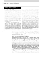
NOTES FROM THE FIELD…
Multiplexing Defined
Multiplexing is defined as the sending of multiple sig-
nals over one communications channel at the same
time. The cable television system is a perfect example
of multiplexing in action. Cable TV is a simple technol-
ogy where your available channels are all sent along
a single cable, and you are able to select a channel
to view a specific program based on your numbered
selection. In the world of data transmission, the tech-
nology is very much the same. If you have a T1, for
example, and you need to break that 1.544 Mbps of
bandwidth down to smaller amount, you can do so with
a fractional T1.
What about the rest of that bandwidth, is it wasted?
Of course not, not with multiplexing. As a service provider,
you can designate half of the bandwidth to company A and
then the rest to company B. Data is sent along the whole
T1, and no bandwidth is wasted. The technology of multi-
plexing is used in many ways to conserve bandwidth.
There are two different types of multiplexing: time
division multiplexing (TDM) and frequency division
multiplexing (FDM). In TDM, each signal is broken up
into many segments, each having short durations or
time slots on the whole of the available bandwidth. FDM
does the same thing as TDM except that TDM is based
on digital signaling and FDM is based on analog.
CHAPTER 3: Network Devices 118
an add-on component for a computer, much like a video card or sound card.
The NIC is normally installed as an expansion board by plugging it into a bus
slot, and it has a connector that allows the network media to be attached to it.
Installing an NIC
Installing an NIC is like installing any other interface card in a computer. You
have to determine the slot it will go in and have the right tools to remove the
expansion slot cover and to remove and insert screws. Newer computers do
not require any tools, not even screwdrivers. The ability to work on a com-
puter with your hands free of tools is making any technician’s job easier. The
Network exam will challenge you to know what to do in certain situations.
In this section you will learn several troubleshooting techniques and how to
recognize the common issues that you will face with network interface cards.
NICs are built for computer bus types such as Industry Standard Architec-
ture (ISA), Extended Industry Standard Architecture (EISA), Micro Channel
Architecture (MCA), and Peripheral Component Interconnect (PCI). Most of
the newer NICs support plug and play features and can be automatically con-
figured by the operating system once the physical installation is done. This fea-
ture makes installation of the NIC considerably easier than with older cards.
Before you begin the physical installation of the NIC, or network adapter,
be sure to address the following issues:
Ensure that the adapter is compatible with the data bus, the protocol,
the media, and the network operating system. In the case of Win-
dows network operating systems, the hardware compatibility list
(HCL) lists adapters that have been verified for use with a particular
operating system (such as NT, 2000, 2003, 2008, Vista, and XP).
Ensure that there is an open bus slot on the machine in which you
want to install the adapter.
Ensure that the adapter includes all items necessary for installa-
tion, including external transceivers or adapters, a T-connector for a
thinwire Ethernet adapter, and product documentation.
Ensure that the software, including the network driver and utilities
for testing and configuring the adapter, is included. If a software
driver is not provided, a driver may be included with operating
system installation media. If not, drivers and driver updates may
be available for download from the adapter manufacturer via the
Internet or a bulletin board service.
Remember that the NIC cannot do any useful work until high-level
protocols and network services have also been installed and configured.
Network Devices 119
EXERCISE 3.1 Enabling and Disabling a Nic Card with Windows XP
Professional
In this exercise we will learn how to enable or disable an NIC card for secu-
rity reasons. If you are not using an interface, disable it. Make sure that you
do not disable interfaces that you may need.
To enable or disable an interface, you need to first open the Network
Connections dialog box. To do this, double click My Network Places on
your desktop. Click View Network Connections, and you will see your cur-
rent connections (Figure 3.4).
FIGURE 3.4
Viewing Your Network
Connections.
CHAPTER 3: Network Devices 120
FIGURE 3.5
Enabling a Connection
with Windows XP
Professional.
Note that in Figure 3.4, LAN has an x. This indicates that the connec-
tion might have an issue, such as a disconnected RJ-45 connector on the
NIC itself. LAN2 is grayed out, indicating that the connection is disabled. To
enable it, you only need to right click the connection and select Enable from
the shortcut menu (Figure 3.5). The NIC will enable itself barring any other
issues, and the icon in the Network Connections window will be shown in
full color.
NIC Types and Operation
Although NICs are all designed to allow computers and devices to access a
network, not all NICs are the same. As we discussed in Chapter 2, there are
many different types of media and connectors that may be used on a net-
work, which is why there are different NICs. Because of this, NICs are often
defined by the following criteria:
The type of Data Link Protocol they support, such as an Ethernet or
Token Ring
The type of media they connect to
The data bus for which they were designed
In using NIC, the computer must have a software driver installed to
interact with the NIC, just as it must for any other peripheral device. These
drivers enable the operating system and higher level protocols to control the
functions of the adapter.
The NICs that exist in the various workstations on a network commu-
nicate with each other using their own unique addresses. The MAC address,
or hardware address, is a 12-digit number consisting of digits 0–9 and letters
Network Devices 121
A–F. It is a hexadecimal (base16) number assigned to the card by the manu-
facturer. The MAC address consists of two pieces: the first signifies which
vendor it comes from, the second is the serial number unique to that manu-
facturer. This address must be unique on each network card on a network.
You may wonder how a manufacturer can ensure uniqueness among all the
network cards in the world. No doubt there are network cards that have
the same address, but each manufacturer is assigned a range by the various
network standards organizations, and they use only that range. Within the
range, a manufacturer may have duplicates, but the duplicates are so spread
out over time that it is almost impossible for a network, small or large, to
have two devices with the same MAC address.
Transceivers
As we discussed in Chapter 2, the term transceiver is short for transmitter-
receiver, and it is a component of an NIC that transmits and receives
electrical signals across the transmission media. Transceivers are also
the part of the interface that actually connects to the media. Although
transceivers can be external to the network card, they are typically built
onto the NIC. A transceiver that’s built onto a card is called an onboard
transceiver.
Although NICs are generally designed to connect to a particular type
of media, they can also connect to multiple media types. A transceiver
type setting is required for network adapters that are capable of attach-
ing to more than one media type. Typical cards of this nature include
Ethernet cards that have both twisted-pair and coaxial connectors. This
is one of the more common oversights in configuring a NIC and the card
can be rendered nonfunctional if it is configured for the wrong media con-
nection. To alleviate this problem, some cards of this type have an auto
setting that causes the card to search for the transceiver that has media
connected to it.
Exam Warning
NICs are the most common interface for a computer or device to connect to media on
the network. They operate at the data link layer of the OSI model.
Exam Warning
Transceivers and media converters are similar in some aspects but are not identical.
Media converters (primarily used with fiber cabling solutions) are used to allow for
connection of different (or dissimilar) connection types or interfaces.
CHAPTER 3: Network Devices 122
Media Converters
Media converters are used when you have two types of dissimilar media that
need to be converged together. Most commonly used when deploying fiber-
based networks, media converters come in handy when you need to connect
up to multiple different connection types, fiber switches, and storage arrays.
These are primarily used and seen on storage area networks (SAN).
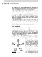
Modern Network Devices
Although many of the devices we’ve discussed so far have been used since
the early days of networking, a number of devices either have taken over the
roles of these devices or are a predominant part of a modern network envi-
ronment. These devices are crucial to a network’s ability to handle data and
ensure it reaches its intended destination as its being transmitted.
Routers
Routers route data packets across a network by opening the packet and
making routing decisions based on the contents. On a network that uses
Transmission Control Protocol/Internet Protocol (TCP/IP) as its communi-
cation protocol, IP addresses are used as a method of identifying computers.
This identification is used to ensure that data is sent to the correct computer
on the network. For these computers to communicate, however, a device is
needed to guide the TCP/IP network traffic to its destination. This is where
routers come in.
The network layer, or Layer 3, is responsible for addressing messages
and translating their logical addresses into an actual physical address. It is
important to remember that a router is protocol dependent. That means that
a TCP/IP router can connect to a TCP/IP network. In other words, this is the
layer of the OSI model that is responsible for determining where to send the
TCP/IP packets to their destinations. Routers essentially separate different
broadcast domains from one another and route traffic based on the destina-
tion, or Layer 3, address (the Layer 2 address is the MAC address).
When you want to communicate with another computer network, your
computer essentially looks within the local network first before heading out
to search for a remote address. For example, when your computer needs to
access a file on another computer, your computer first checks its Address
Resolution Protocol (ARP) cache to see if that computer has a recognizable
MAC address. If it does not, your computer checks the local subnet by either
broadcasting or asking a name server for help.
If the address is not found on the local subnet or network, your computer
checks to see if you have a default gateway or router to send the information
Network Devices 123
to. Your computer sends this information to your router and the router routes
the message accordingly. The router receives the data with the address infor-
mation and checks its routing tables to see where it should send your data.
The type of router sometimes affects how quickly your data arrives at its
destination.
Routers are either static or dynamic. In most cases, you’ll only have to
deal with a dynamic router – a router whose routing tables are populated
automatically by receiving updates from other routers. Static routers have
fixed routing tables that have to be updated manually. These static routers
are at a disadvantage because they cannot communicate with any type of
router in case a network route changes due to hardware failure or change to
the network layout.
The main benefit of a dynamic router is that, depending on which type
of routing protocol is used, it will attempt to route your network traffic to
your destination as quickly as possible, for example, if you have a network
that is standardized on Cisco routers (dynamic) that all communicate with
one another using the Open Shortest Path First (OSPF) Routing Protocol.
All of your routers are communicating with one another via broadcasts that
they send whenever there is a change in their routing. This comes in very
handy and adds a layer of redundancy so that if a segment of the network
fails, your routers will be able to route the network traffic through other paths
so that no matter what happens to the network, your data will always arrive
at its destination.
If you were using a static router and you had a segment fail on your net-
work, your network traffic would cease until the segment was repaired or
another static route was mapped on the router. This puts static routing at a
severe disadvantage in a large, complex network environment.
Understanding Static and Dynamic Routing
When it comes to routing, there is a huge difference between static and
dynamic. Early routers had to be programmed with exactly which networks
they could route between which interfaces, especially if there were many
network interfaces. This is called static routing, and network administra-
tors had to add, maintain, and delete routes of the network routing devices
manually. In a small company this may not be much of a chore, but for
medium to large networks, this can be nearly impossible. These larger net-
works almost always employ many logical subnets, which require you to
update the route tables on each routing device. If these remote subnets are
connected by routers with static route tables, you have to add the exact static
route to communicate between the two subnets. Table 3.3 shows an example
of what is contained in the routing table.
CHAPTER 3: Network Devices 124
In this simplified table you can see how you only specify the router to be
used to reach the destination, not the actual destination itself. The number
of hops determines which route is the most efficient. If a route claims it can
reach the destination in one fewer hop than the next router, then it is sent
to that router. If there are two identical routes to the same destination, the
route with the fewest hops will be used.
One change to a network address means visiting every routing device
that employs static routing and updating the entry. What do we do if our net-
work is fairly large and complex? We must then use routing devices capable
of dynamically updating the routing tables.
Dynamic routing does not require the network administrator to edit
complex routing tables to communicate with other networks or segments.
These routers communicate with each other using a powerful routing pro-
tocol such as Routing Information Protocol (RIP) or OSPF. They can also
query other routers for updated route information, which can create more
efficient paths for sending packets or locate an alternative route if the origi-
nal route fails. The routers can broadcast the routes they have discovered
to neighboring routers, and, in turn, accept routes from other neighbor-
ing routers. The Internet comprises many dynamic routers, which is an
example of why dynamic routing is so important. Could you imagine hav-
ing to update a static routing table on thousands of static routers? I don’t
think so.
These dynamic routers, however, cannot update the route tables of static
routers or non-dynamic routers. There are a few situations in which inte-
grating static and dynamic routers is acceptable:
When you have a router at either end of a slow WAN link: This
router will not increase traffic by broadcasting updated route infor-
mation to the router on the other end of the link.
When you require a packet to travel the same path each time to a
remote network, add the path you would like the packet to take to
Table 3.3
Information Contained in a Routing Table
Destination Adjacent Router Hops
Network 1 Router A 1
Network 1 Router B 2
Network 2 Router B 2
Network 2 Router C 3
Network 3 Router D 3
Network Devices 125
reach the destination network. You cannot enter the entire path
over several routers, only the path to the first router.
When you want to configure a static router to point towards a
dynamic router to take advantage of the dynamic router indirectly.
This is the next best thing to using a dynamic router. You can hand
off the packet to the dynamic router and let this router determine
the most efficient path to the destination based on the paths it has
learned from neighboring dynamic routers.
Switching Routers
Switches have the ability to perform the tasks normally associated with other
devices. A Layer 3 switch has the ability to open a packet and view the IP address
and MAC address of the computer the packet is destined for. The switch can
then review routing tables on the switch to determine the best route to send
the data. By performing these functions, the switch is able to do the work of a
router and get the packet to its intended destination by using the best route.
Security Integration
As reports of hacking, viruses, worms, and other attacks on networks become
commonplace in the news, the need for security in network devices and net-
works in general continues to grow. Equipment and software can be added to
a network, which can work with existing devices to protect your LAN and its
data. Choosing which security measures to implement can be challenging,
as there is an increasing number of products available. However, the more
protected your network, the less chance there will be of it being damaged
from outside sources.
Convergence of Security
Just as devices are including more and more features in them that make other
devices obsolete or unnecessary to a network, devices are also including more
security features that historically had to be purchased separately. As demon-
strated with routers that are used for DSL or cable Internet, features such as a
built-in firewall are now being included with the router. The hardware-based
firewall provides a barrier to incoming traffic from the WAN, and thereby pre-
vents it from reaching your local computer or LAN. The hardware firewall, how-
ever, is limited in restricting and monitoring the incoming and outgoing traffic
and should be complemented by a software firewall and antivirus software.
Exam Warning
Routers operate at the network layer of the OSI model. The exam will deal with questions
regarding both routers and the OSI model.