CompTIA Network+ Certification Study Guide part 18 pdf
Bạn đang xem bản rút gọn của tài liệu. Xem và tải ngay bản đầy đủ của tài liệu tại đây (103.41 KB, 10 trang )
CHAPTER 4: Switching 156
is the process of sending data from segment to segment based on the MAC
address, what happens when data has to be sent to a remote network? The
data is sent to the default gateway (commonly a router), which sends the data
to its destination. The time spent sending the data from the switch to the
router and then the time spent by the router taking the packet off the wire to
read it is now eliminated or shortened drastically by implementing a multi-
layer switch. This is because a Layer 3 switch is built into a Layer 2 switch
so data does not have to be sent to a router; that is, the router is built into
the circuitry of the switch so the data is routed as quickly as the switch can
send it to itself – much quicker than one device trying to send data to another
device. Now consider the speed at which a high-speed switch works. Con-
sider the amount of packets that could be sent across that cable. Now you
can start to see the benefits of a multilayer switch; having the two devices
sandwiched together increases the efficiency of the transmission, thus speed-
ing it up drastically as the volume of data increases.
CONTENT SWITCHES
Because of the success of Layer 3 switching and the performance gains it can
provide, it was no surprise that switching would climb higher along the OSI’s
layered model. Content switches use Layers 4 to 7 of the OSI model, and
rather than looking at the individual packets being transmitted, they can use
sessions to transmit data between machines. Content switches will also take
advantage of caching and load balancing so that the amount of data trans-
mitted across networks and requests processed by a server are reduced.
Content switches that use Layer 4 work at the transport layer of the OSI
model and have the ability to look at information in the packets it receives
to not only identify the MAC address and IP address of the destination com-
puter, but also the application protocols being used to send it. The switch
can determine if Hypertext Transfer Protocol (HTTP), File Transfer Protocol
(FTP), or other protocols in the Transmission Control Protocol/Internet Pro-
tocol (TCP/IP) suite are being used to send the packet and can also identify
the application that uses the data. Because the packet contains information
about the application, priorities can be set on packets, as well as rules about
how they are to be forwarded.
Layer 5 switching works at the session layer of the OSI model, and uses
information in the packet provided by this layer for routing. The session layer
provides information such as uniform resource locators (URLs) that allow
the switch to route the packet more effectively to a destination computer.
A URL is a method of addressing that is commonly used on the Internet.
Advanced Features of a Switch 157
Layer 6 switching works at the presentation layer of the OSI model, while
Layer 7 switching works at the application layer of the OSI model. Switches
that use these upper layers have the ability to look at the content of the data
being transmitted. An example of this would be an .XML file that was being
sent across the network. The Layer 7 switch could look at the tags within
the file to determine where the file should be sent. Because it works at the
highest level, it has the ability to use information from all levels of the OSI
model for use in forwarding the data to its proper destination.
ADVANCED FEATURES OF A SWITCH
Although we’ve discussed a number of different types of switches and seen
how they work differently and provide diverse features, there are also switches
available in the marketplace that offers enhanced features. These elements
bring improved security, services, and capabilities that were unseen in basic
switches that were available in previous years. Some of the advanced features
we’ll discuss in the sections that follow include:
Power over Ethernet (PoE)
Spanning Tree Protocol
Virtual LANs
Trunking
Port Mirroring
Port Authentication
Power over Ethernet
Power over Ethernet (PoE) is a technology in which electrical power can
be transferred over standard twisted-pair cables. Although data have always
been transferred along the wires used on an Ethernet network, PoE allows
electricity to also be transferred along the same cabling. This means that
no modification needs to be made to the existing cabling of a network to
implement PoE.
Exam Warning
Switches operate at many layers of the OSI model. They work at the data link layer
(Layer 2), and sometimes at the network layer (Layer 3) of the OSI model. Layer 3
switches have an integrated router function that allows them to make decisions as to
where the data should be sent.
CHAPTER 4: Switching 158
PoE is used to provide power to devices that are connected to a network
and allows them to acquire power without the need of having to use existing
outlets or pay for new power sources to be installed. Some devices that com-
monly use PoE are network cameras, IP telephones, wireless access points,
remote switches, or other network devices.
A benefit to PoE is that so long as the switch is connected to a power
source, any of the devices using PoE through that switch will continue to
receive power. In other words, if the switch is connected to a uninterruptible
power supply (UPS), any of the devices using PoE on that switch will con-
tinue running even if there is a power failure.
Spanning Tree
The Spanning Tree Protocol (STP) was developed by Digital Equipment
Corporation (DEC) to prevent broadcast storms that result from looping.
A broadcast is a message that is sent across a LAN at the data link layer
(that is Layer 2 of the OSI model), and it can be forwarded by switches to
other segments of the network. When a switch has more than one way to
communicate with a node, it can cause broadcasts to go out across more
than one path. This can create a loop in the way this data travels across the
network. When data loops endlessly around the network in this way, it eats
up the available bandwidth and can affect network performance. Not only
can computers on the network experience slow response times, but they also
can have problems just logging into the network.
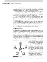
To illustrate the problems with looping and how STP fixes this, let’s
look at Figure 4.1. As shown in this figure, the network on the left has two
switches connected together. Although this prevents data from being passed
to multiple switches, it also creates a single point of failure on the network.
If one switch fails to work, then data cannot be transferred across the net-
work. The network on the right provides multiple paths that data can be
DAMAGE AND DEFENSE
Switching on Networks
In terms of devices that provide network connectivity,
switches have become the future of networking. Today’s
computer networks have to support the combination
of voice, video, and data, so many network adminis-
trators are beginning to favor intelligent switches over
common shared hubs. Network switches enable you to
have bandwidth on demand and ensure that you can
use your network to the fullest capacity. If you have a
switch that is capable of 100 Mbps, you are guaran-
teed that amount of bandwidth due to the way a switch
can intelligently look at the packets. A shared hub, on
the other hand, can sometimes supply only 40 percent
of the potential bandwidth on the network.
Advanced Features of a Switch 159
transmitted across, but it creates the problem of looping. If you imagine data
going across two switches, you can follow in this figure how the data could
be passed from one switch to another endlessly.
The STP uses an algorithm that identifies that a switch has multiple
ways of communicating with a single node. In identifying this, it then deter-
mines the best way of communicating with that node and blocks out the
other paths. If the primary path to a node becomes unavailable, it will then
use redundant links to that node. This means that in the event of failure, the
network can still continue to function without worry that loops will result
and flood the network.
VLAN
A VLAN is a virtual LAN that allows messages to be broadcast to all of
the network devices that are in the same broadcast domain. A broadcast
domain is a logical division of computers that can communicate with one
another using broadcast messages. VLANs are used to allow computers and
other network devices to appear as if they are on the same network segment,
regardless of where they are physically located.
Ports on switches supporting this technology can be configured to be part
of the same VLAN. For example, some of the ports in one switch could be set
to be part of VLAN A and ports on another switch could also be set to part of
VLAN A. From the perspective of the devices on this VLAN, they are all part
of the same broadcast domain and can communicate with one another using
broadcast messages, which would not be received by any computers or devices
that are not part of this VLAN.
Trunking
In using VLANs, there may be situations where you have different computers
that are on the same VLANs but in different locations that are connected by
a single network link. This might be computers on different floors or build-
ings where a single cable is used to connect the different network segments.
FIGURE 4.1
Spanning Tree Allows
for Redundant Paths to
Nodes.
CHAPTER 4: Switching 160
To prevent the data from different VLANs from being sent across the single
cable and being received by the wrong VLANs, a process called trunking
is used.
Trunking is a term that refers to a single network link that allows mul-
tiple VLANs to communicate with one another. Two switches can send and
receive the network traffic from two or more VLANs using a Trunking Pro-
tocol. When a packet of data is sent between the two switches, a tag is added
to the frame header, indicating that it belongs to a particular VLAN.
To illustrate this, let’s say that a computer on one floor of a building is
part of VLAN A. The user wants to send data to another computer that’s on
another floor and is part of the same VLAN. The data is sent to the switch,
but because there are multiple VLANs on these floors, the switch adds infor-
mation to the header of the packet saying that this data is for a computer on
VLAN A. When it reaches the switch on another floor, this second switch
looks at the header and realizes that it should be sent to VLAN A. Even
though multiple VLANs may use the network link between these floors of
the building, the data are sent to the proper VLAN using this method.
Port Mirroring
Port mirroring is a process in which all of the data sent or received on
one port or VLAN is copied to another port, and it is also known as a
switched port analyzer (SPAN) or roving analysis port (RAP). In looking at
these terms, you can see that port mirroring is used for analyzing network
traffic. The data copied to a port on a switch can be copied to a different
port on the switch, which is then sent to a computer or network appliance
that monitors the traffic. An example of one such device that would use port
mirroring would be an intrusion detection system (IDS), which monitors
network traffic for activity that’s indicative of unauthorized access. Network
administrators using the data that’s been forwarded by port mirroring can
then identify issues with switch performance and can be notified of prob-
lems on the network.
Port Authentication
Port authentication is a process in which access to a port is given to a device
by having that device authenticate itself with a server. Port authentication
is part of the IEEE 802.1x standard, which outlines how access to a network
can be restricted on a port-by-port basis. Access control is based upon devices
authenticating themselves before being allowed to transmit packets across
the network. Once the device has authenticated itself, communication over
the port is allowed, so that it can then transfer data across the switch and
over the network.
Summary of Exam Objectives 161
Port authentication requires several components for access to be given or
denied. These are as follows:
Supplicant This is the client that requests access to the network.
This may be a computer, software, or network device that requires
access to the network.
Authenticator This is the port that is configured to restrict access
and requires authentication before allowing access.
Authentication server This is a server that verifies the credentials of
the supplicant and determines if access should be granted or denied.
The way port authentication works is the supplicant (such as a network
workstation) attempts to access a port on a switch. The port acts as the
authenticator and won’t allow access until the supplicant has been authen-
ticated. The supplicant gives a username/password, digital certificate, or
other credentials to the authenticator, which passes this information to an
authentication server. The authentication server may be a RADIUS data-
base or another authentication database that compares the credentials to
its own records to determine whether access should be granted. The result
of this comparison is sent back to the authenticator. If the credentials have
been verified and found to be valid, then the supplicant is allowed to access
resources and transmit data across the switch.
SUMMARY OF EXAM OBJECTIVES
Switches can provide an array of features that can enhance the security and
functionality of a network. At its most basic level, a switch is a network
device that allows multiple devices to communicate with one another on a
network. These devices can be workstations, servers, laptops, printers, or
any number of other devices that require the ability to send and receive data
with one another.
Switches can work at different levels of the OSI model. Depending on the
layer used by the switch, it replaces many of the devices previously used on
older networks, inclusive to repeaters and bridges that we discussed in the
last chapter. Switches can provide the function of connecting together the
multiple networks, segmenting networks, or provide routing features that
will get data to its proper destination using the fastest possible route.
Test Day Tip
Remember for the Network+ exam that each component’s functionality is listed on the
testable objectives at the beginning of this chapter.
CHAPTER 4: Switching 162
Switches can also include a number of advanced features. PoE can provide
power to devices connected to the network, whereas VLANs can be used to
connect different computers into VLANs and join them together in the same
broadcast domain. If the VLANs are connected using a single network link,
Trunking Protocols may be used to provide connectivity. Security features
like port authentication can be used to require a client to authenticate to a
server before gaining access to a port. Some switches will also provide the fea-
ture of port mirroring, so that data sent to one port can be sent to hardware or
software that monitor network traffic. As you can see by this, switches have
evolved over the years. Although they still have the primary purpose of direct-
ing network traffic, they are a critical component of any larger network.
EXAM OBJECTIVES FAST TRACK
Understanding Switches
Switches provide services that are similar to those found in Ether-
net hubs. A switch takes data from a cable connected to its port,
but unlike a hub that forwards the data through all of its other
ports, a switch will forward the packet only to the computer that
the data is intended for.
Broadcast messages are the messages that are sent out to all of the
nodes in a broadcast domain. A broadcast domain is a logical divi-
sion of computers that can communicate with one another using
broadcast messages.
The OSI model is a reference model that is used to map different
functions of network communication. Types of switches are often
identified by how they relate to specific layers of this model.
Basic Switches
Basic switches look at the MAC address of a packet to determine
where it is destined. The MAC address is unique to the NIC and
makes it identifiable on the network.
Layer 2 switches work at the data link layer (Layer 2) and look at
the MAC address of the packet to determine where it is to be sent.
Switches are also sometimes referred to as multiport bridges, because
they can perform the same functions as a bridge. They can connect
two LANs together or segment a large LAN into two smaller ones.
Exam Objectives Fast Track 163
Multilayer Switches
A multilayer switch (also called a Layer 3 switch) works by utiliz-
ing switching tables and switching algorithms to determine how
to send data via MAC addressing from host to host or device to
device.
Layer 3 switches work at the network layer of the OSI model and
have an integrated router function that allows it to make decisions
as to where the data should be sent.
A Layer 3 switch is built into a Layer 2 switch so data does not have
to be sent to a router; that is, the router is built into the circuitry of
the switch so the data is routed as quickly as the switch can send
it to itself – much quicker than one device trying to send data to
another device.
Content Switches
Content switches use Layers 4 to 7 of the OSI Model, and rather
than looking at the individual packets being transmitted, they can
use sessions to transmit data between machines.
Switches that use the upper layers of the OSI model have the ability
to look at the content of the data being transmitted.
Content switches take advantage of caching and load balancing so
that the amount of data transmitted across networks and requests
processed by a server are reduced.
Advanced Features of a Switch
A VLAN allows messages to be broadcast to all of the network
devices that are in the same broadcast domain.
Trunking is used to allow multiple VLANs to communicate with
one another across a single network link.
PoE is a technology in which electrical power can be transferred
over standard twisted-pair cables.
Port mirroring is used to allow all of the data sent or received on one
port or VLAN is copied to another port, and is also known as a SPAN
or RAP. The copied data can then be used by hardware or software to
monitor the data, as in situations where IDS are used.
CHAPTER 4: Switching 164
The STP is used to prevent broadcast storms that result from
looping.
Port authentication is a process in which access to a port is given to
a client by having it first authenticate to a server.
FREQUENTLY ASKED QUESTIONS
I am creating a small home-based network that will connect several Q:
different computers together. Because switches are commonly used
on our network at the office, should I use one for this network as
well?
A hub would be a better solution, as they are less expensive and A:
the features of a switch aren’t really necessary for this situation.
Although switches are the optimum choice for networks, they
aren’t always the best choice for small networks consisting of sev-
eral computers. In most cases where there are just a few computers
connected together, a switch would be overkill and a more costly
solution.
I am creating a new Ethernet network that will consist of a few Q:
dozen employees and will expand greatly over the next few years.
Which device should I use to connect users together on the net-
work and still have the ability to expand as the network grows?
A switch is similar to a hub in that it will take data from one cable, A:
regenerate the signal, and then resend it. What makes a switch
different is that it will take the data sent to one port on the switch,
and then determine which of the other ports will allow the data
to get to its intended destination. Switches have also incorporated
many of the functions previously provided by other network devices,
and can be connected together when there is a need to expand
the network.
SELF TEST
You have purchased a basic switch for your network that can look 1.
at information within a packet of data and send it to its destination
address. It has no additional features. What kind of switch is this?
A. Layer 2
B. Layer 3
Self Test 165
C. Layer 4
D. Layer 5
A broadcast message is sent by a computer onto the network. 2.
Which of the following will occur when the switch receives the
broadcast message?
A. The message will be sent to all computers on the network.
B. The message will be sent to all computers in the same broadcast
domain.
C. The message will not be sent because switches will only send
messages between two nodes.
D. The message will not be sent because switches are designed to
always ignore broadcast messages.
You are looking into purchasing a new switch for your network. You 3.
want the switch to be able to route packets of data based on the
uniform resource locator included with the packet. Which switch
type should you buy?
A. Layer 2
B. Layer 3
C. Layer 4
D. Layer 5
A switch on your network is designed to look at the MAC address 4.
of incoming data, and then use switching tables and algorithms to
properly route data to its intended destination. What type of switch
is being used?
A. Layer 2
B. Layer 3
C. Layer 4
D. Layer 5
Your company has just purchased a smaller rival business, and 5.
now wants you to connect the two networks together. Your com-
pany’s existing network is twice the size of the new network. To
get these two networks connected together, which of the following
will you do?
A. Install a VLAN to connect the two networks together.
B. Install a switch to connect to the two networks together.