CompTIA Network+ Certification Study Guide part 26 potx
Bạn đang xem bản rút gọn của tài liệu. Xem và tải ngay bản đầy đủ của tài liệu tại đây (207.5 KB, 10 trang )
CHAPTER 6: The OSI Model and Networking Protocols 236
closely together and that is why it’s hard to discuss one without the other.
As a matter of fact, no matter how long you are in networking, you will find
the OSI model is referenced on a daily basis all the way from the beginning
as a student to a networking master.
In this chapter, we look at the networking models that provide
guidelines for vendors of networking products, including the early Depart-
ment of Defense (DoD) model as well as the International Organization for
Standardization (ISO) OSI model.
Next, we move into the protocol suite. The majority of TCP/IP
fundamentals will be covered in Chapter 7. You’ll also learn about the
protocols that are used throughout the network communication process
to ensure that data sent from a computer reach their intended destination.
We also discuss popular networking protocols upon which majority of
the Internet applications run. Now, let’s start with the OSI model and
understand why it’s so important.
Understanding the Purpose and Function
of Networking Models
This chapter discusses several specific networking models, so it’s important
to begin our discussion with an overview of the purpose and function of
networking models. Just about everywhere we look in the world today, we
can see examples of agreed-upon rules that help people work together more
effectively and efficiently to achieve a specific aim. This is especially true in
the world of technology where standards, specifications, and protocols are
used to accomplish a particular task. Why is it you can pop a DVD in your
player and watch it, regardless of who made the DVD, the DVD player, or the
television? It’s because everyone involved agreed to certain parameters such
as the circumference of the DVD disk, the method of recording and reading
the DVD, and the interface between the DVD player and the television.
The same is true in computer technology. A wide variety of methods
can be used to transmit and receive data across a network. Models are used
to broadly define the required elements. This helps break down complex
tasks into more manageable segments. It also provides frameworks from
which standards can be developed. Organizing networking tasks in this way
provides standardization, which is critical for any technology to be widely
adopted. It also reduces development time and cost because common tasks
are defined and can be implemented without “reinventing the wheel.” An
excellent example of an organization dedicated to providing solid standards
for networking is the Institute of Electrical and Electronics Engineers (IEEE),
which will be covered shortly within this chapter.
The OSI Model 237
The DoD networking model was originally created to solve the problem
of people needing to share information across large computer systems. That
model was used as the basis for an expanded model known as the OSI
model. Later in this chapter, we cover the DoD model. Although the exam
primarily focuses on the OSI model, you should still be familiar with its
existence and how it maps to the OSI model.
THE OSI MODEL
The OSI model was originally developed at Honeywell in the mid-1970s and
expanded upon the Defense Advanced Research Projects Agency (DARPA) model.
In 1977, the ISO recognized the need to develop a communication standard
for computing. They formed a subcommittee called the OSI committee and
asked for proposals for a communication standard. Honeywell’s solution, called
distributed systems architecture (DSA), included seven layers for communica-
tions. This framework was adopted by the OSI and is still used as the model for
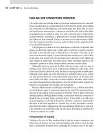
distributed communications. The OSI model is shown in Figure 6.1.
We’ll explore each of the seven layers of the OSI model in the following
subsections. The first two layers of the OSI model involve both hardware
and software. In the five upper layers (Layers 3 through 7), the OSI model
typically is implemented via software only.
Exam Warning
Knowing that the OSI model is imperative, you need to know which devices and protocols
function at each layer, so you need to know the layers to start with. Continue to draw the
model shown in Figure 6.1 so that when you get to the exam, you can write it on scrap
paper to help you with the exam.
Test Day Tip
Some exams may ask you to identify the seven layers of the OSI model, as well as
to identify the definitions of one or more layers. An acronym used to remember the
seven layers of the OSI model is all people seem to need data processing. This equates
to application, presentation, session, transport, network, data link, and physical. By
remembering this acronym, you’ll easily remember the seven layers (in reverse order).
Remember that numbering starts at the bottom of the model.
More commonly, the Network
exam requires you to know and understand what
happens at each layer, and which protocol operates there (rather than just rote memoriza-
tion of the layers themselves) to be able to troubleshoot common networking problems.
CHAPTER 6: The OSI Model and Networking Protocols 238
The OSI model is represented as a stack because data that are sent
across the network have to move through each layer at both the sending
and receiving ends. The sending computer generally initiates the process
at the application layer. The data is then sent down the stack to the physi-
cal layer and across the network to the receiving computer. On the receiv-
ing end, the data is received at the physical layer and the data packet sent
up the stack to the application layer.
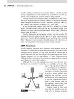
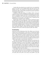
A good visualization of this can be
seen in Figure 6.2, where Computer
A wants to browse a Web site home
page of Server B, such as www.
syngress.com/index.htm.
To view how this works, con-
sider these facts. The home page
index.htm is the file that is located
in a folder (or directory) on the Web
server, and this is what Computer
A wants to view. Computer A is
connected to an Internet service
provider (ISP) via a home PC, a net-
work interface card (NIC), a cable
modem, or whatever the ISP requires
for connectivity. Computer A opens
a Web browser (which is an appli-
cation), the Web browser (not need-
ing to know anything other than to
make a request to the Web server)
sends the request, and underlying
protocols process it. The application
layer (not to be associated with the
application itself) starts the process.
Encapsulation (addition of small
pieces of information relative to the
transmission of information) hap-
pens at each layer, with each layer
adding its information to the data
to get it to the Web server, and then
reversing the process to get informa-
tion back again. As you can see, you
only see the request; the Web server
will answer back with index.htm.
FIGURE 6.1 The OSI Networking Model.
FIGURE 6.2 Viewing a Web Page Using the
OSI Model.
The OSI Model 239
The beauty of this depiction is that it is very easy to see and clearly under-
stand why you absolutely need to know the OSI model and what happens
at each layer.
Layer 1: Physical
The first, most basic layer of the OSI model is the physical layer. This
layer specifies the electrical and mechanical requirements for transmitting
data bits across the transmission medium (cable or airwaves). It involves
sending and receiving the data stream on the carrier, whether that carrier
uses electrical (cable), light (fiber optic) or radio, infrared, or laser (wireless)
signals. The physical layer specifications include as follows:
Voltage changes
Timing of voltage changes
Data rates
Maximum transmission distances
Physical connectors to the transmission medium
Topology or physical layout of the network
Many complex issues are addressed at the physical layer, including digital
versus analog signaling, baseband versus broadband signaling, whether data
HEAD OF THE CLASS…
Advanced Networking
You don’t need to know very advanced levels of net-
working for the exam. The testing will not dig down
into packet headers, encapsulation types, and so on,
but if you want to make a career out of networking,
you will eventually need to know this information. For
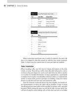
that reason, let’s dig into the OSI model a little more
(Figure 6.3).
As Computer A wants to visit the Web site of
syngress.com, the Web browser on the local PC is
where the uniform resource locator (URL) is entered
into the browser application’s address area. In this
example, www.syngress.com is entered and then
the real magic happens. As the request heads to the
server, the OSI model handles the request, and Figure
6.4 shows all the things that are happening, such
as IP addressing information, Media Access Control
(MAC) address information, and so on. All these will
be explained in the following sections, but this is how
you could mentally map the data transmission in your
head. Remember that this chart and information is not
needed for the exam but for your general understand-
ing of the topic.
Again, knowing the OSI model information provides
a foundation for you to grow and build on. Let’s now dig
into the specifics of each layer starting from the lowest
layer, the layer that makes use of the physical trans-
mission medium, the physical layer.
CHAPTER 6: The OSI Model and Networking Protocols 240
is transmitted synchronously or asynchronously, and how signals are divided
into channels (multiplexing).
Devices that operate at the physical layer deal with signaling, such as
the transceivers on the NIC and the basic and simple connectors that join
segments of cable.
Digital Versus Analog Signaling
These days, in the “digital age,” there is hardly a day that goes by without the
need surfacing for some form of electricity in your life. So what is this analog
signaling and why so much concern? Well, because as a Network techni-
cian, you need to understand how different types of technology work, and
the perfect example to drive this home would be the modem, a device that
a great many people use every day to access the Internet via their standard
preexisting telephone lines.
A modem is a device that Mo… (Modulates) Dem… (Demodulates) a
signal, or in easier to understand terms… the modem translates an analog
system signal to a digital system signal and back again so that the signal can
traverse along the Plain Old Telephone Service (POTS). It should then make
sense to the PCs sending and receiving it, as the modem does the PC the
favor of taking that analog signal and translating it into a digital one, which
is what your PC natively understands.
FIGURE 6.3 Viewing More Detail within the OSI Model.
Exam Warning
Modems translate analog to digital signals and back again. PCs are using digital
technology to communicate, but the phone lines are using analog signaling. Therefore,
the signal must be changed from one signaling method to the other as needed, such as
when you want to connect your PC up to your ISP and surf the Internet.
The OSI Model 241
So what is analog? Analog signals
are electronic signals that are based
on a wave that moves up and down
continuously (as shown in Figure 6.4).
A more technical definition of this
technology is that analog signals are
electronic signals that are transmitted
by adding a signal of varying frequency
or amplitude to a carrier wave of a
given frequency of alternating electro-
magnetic current. For the Network
exam, don’t worry too much about
the technical jargon here. Under-
standing this function will help you
to understand what the physical layer
of the OSI model is responsible for
and why.
Analog signals, although com-
monly used today (consider the tele-
phone in your home), are actually not
commonly used for new installations.
Nothing new implemented today
in technology uses analog anymore:
most if not all of it winds up in digital
format. Digital communications are
more compatible with PCs because
that’s how PCs operate, via digital
technology. Digital signals are more
reliable and easier to transmit. For this
reason, it should be clear as to why
digital is so important to understand
and learn. As shown in Figure 6.5,
you should see that since computers
operate on 1s and 0s, digital (either
being on or off, like a light switch if
you will) fits binary math perfectly.
1 or 0, on or off. Now that you have
seen both signaling methods, let’s
move on to possible issues based on
digital technology.
FIGURE 6.4 Analog Signaling.
FIGURE 6.5 Digital Signaling.
CHAPTER 6: The OSI Model and Networking Protocols 242
Issues like attenuation (degradation of the signal) can really ruin digital
communications. For example, if you were installing a PC over 150 m away
from the concentrator it is connected to, (10BaseT technologies have a
maximum allowed distance of about 100 m or 328 ft), the signal is likely to
degrade (Figure 6.6).
As Figure 6.6 shows, because the signal has degraded, the 1s and 0s
become “unknowns” because they fall short of being either a 1 or 0. This
example shows how exceeding maximum cable distances will in fact cause
you issues later on.
In sum, when dealing with the physical layer, the data handled is in
bits, literally 1s and 0s. These 1s and 0s are represented by pulses of light
or electricity (“on” generally represents 1 and “off” generally represents 0).
How these bits are arranged and managed is a function of the next layer in
the OSI model.
Layer 2: Data Link
Layer 2 is the data link layer. This layer is responsible for maintaining the
data link between two computers, typically called hosts or nodes. It also
defines and manages the ordering of bits to and from data segments, called
packets. Frames contain data arranged in an organized manner, which
provides for an orderly and consistent method of sending data bits across
the medium. Without such control, the data would be sent in random
sizes or configurations and the data that was sent on one end could not
be decoded on the other end. The data link layer manages the physical
addressing and synchronization of the data packets (as opposed to the logi-
cal addressing that is handled at the network layer). The data link layer is
also responsible for flow control and error notification. Flow control is the
Test Day Tip
Don’t get confused about terminologies such as Baseband and Broadband. Make sure
you understand the following:
Baseband is a method of data transmission where all bandwidth on the transmission
medium is used to transmit a single digital signal. As you saw in Figure 6.6, Baseband
technology uses digital signaling.
Broadband is a method of data transmission where the bandwidth on the transmis-
sion medium is broken into channels that are capable of supporting a wide range of
frequencies.
Make sure you are comfortable with the terminology and that you understand what
each is and does. It will be important to understand, as you learn about 10BaseT, that
the Base stands for Baseband. 10BaseT runs at 10 Mbps, it has a 100 m limit on
distance. The T is for twisted-pair cabling.
The OSI Model 243
process of managing the timing of
sending and receiving data so that it
doesn’t exceed the capacity (speed,
memory, etc.) of the physical con-
nection. Because the physical layer
is responsible only for physically
moving the data onto and off of
the network medium, the data link
layer also receives and manages
error messaging related to physical
delivery of packets.
Network devices that operate at
this layer include Layer 2 switches
(switching hubs) and bridges. A
Layer 2 switch decreases network
congestion by sending data out only
on the port to which the destina-
tion computer is attached, instead
of sending it out on all ports, as a
physical layer hub does. Bridges
provide a way to segment a network
into two parts and filter traffic by
building tables that define which
computers are located on which side of the bridge, based on their MAC
addresses.
The data link layer is divided into two sublayers: the Logical Link Control
(LLC) and the MAC. These were originally seen in the OSI model diagram
in Figure 6.1.
The LLC Sublayer
The LLC sublayer provides the logic for the data link, thus it controls the
synchronization, flow control, and error checking functions of the data link
layer. This layer can handle connection-oriented transmissions (unlike the
MAC sublayer below it), although connectionless service can also be provided
by this layer. Connectionless operations are known as Class I LLC, whereas
Class II can handle either connectionless or connection-oriented operations.
With connection-oriented communication, each LLC frame that is sent is
acknowledged. The LLC sublayer at the receiving end keeps up with the LLC
frames it receives (these are also called protocol data units [PDUs]), and if
it detects that a frame has been lost during the transmission, it can send
back a request to the sending computer to start the transmission over again,
beginning with the PDU that never arrived.
FIGURE 6.6 The Effects of Attenuation on
a Digital Signal.
CHAPTER 6: The OSI Model and Networking Protocols 244
The LLC sublayer sits above the MAC sublayer and acts as a liaison
between the upper layers and the protocols that operate at the MAC sublayer
such as Ethernet, Token Ring, and so on (IEEE standards). The LLC sublayer
itself is defined by IEEE 802.2. Link addressing, sequencing, and definition
of service access points (SAPs) also take place at this layer.
The MAC Sublayer
The MAC sublayer provides control for accessing the transmission medium.
It is responsible for moving data packets from one NIC to another across a
shared transmission medium, such as an Ethernet or fiber-optic transmission
medium.
Physical addressing is addressed at the MAC sublayer. Every NIC has a
unique MAC address, also called the physical address, which identifies that
specific NIC on the network. The MAC address of a NIC is usually burned
into a read-only memory (ROM) chip on the NIC. Each manufacturer of
Exam Warning
A MAC address consists of six hexadecimal numbers. The highest possible hexadecimal
number is FF:FF:FF:FF:FF:FF, which is a broadcast address. The first three bytes contain
a manufacturer code and the last three bytes contain a unique station ID. You must
understand the functionality of a NIC card and what a MAC address is for the Network
exam. On Ethernet NICs, the physical or MAC address (also called the hardware address)
is expressed as 12 hexadecimal digits, arranged in pairs with colons between each pair,
for example, 12:3A:4D:66:3A:1C. In binary notation, this translates to a 48-bit (or 6-byte)
number, with the initial three bytes representing the manufacturer and the last three
bits representing a unique NIC made by that manufacturer. On Token Ring NICs, the
MAC address is 6 bytes long, too, but the bits of each byte are reversed; that is, Ethernet
transmits in canonical or least significant bit (LSB) mode, with the least significant bit first,
whereas Token Ring transmits in noncanonical or most significant bit (MSB) mode, with
the most significant bit first. Although duplicate MAC addresses are rare, they do show up
because some manufacturers have started to use their numbers over again. This usually
is not a problem because the duplicates almost never show up on the same network.
Some cards allow you to change the MAC address by using special software to “flash” the
card’s chip. You can view the MAC address on most systems with the following commands.
Windows ME, 9x: winipcfg (navigate the graphical user interface [GUI] to find the MAC
address)
Windows NT, XP, 2000, 2003: ipconfig /all
Linux: ifconfig -a
On Linux, an Ethernet network interface is commonly seen as eth0. Under this
information, you will find the relevant MAC for your system.
The OSI Model 245
network cards is provided a unique set of MAC addresses so that (theoretically,
at least) every NIC that is manufactured has a unique MAC address. Obvi-
ously, it would be confusing if there were two or more NICs with the same
MAC address. A packet intended for NIC No. 35 (a simplification of the MAC
address) would not know to which NIC No. 35 it was destined. To avoid this
confusion, MAC addresses, in most cases, are permanently burned into the
NIC’s memory. This is sometimes referred to as the burned-in address (BIA).
Another important issue that’s handled at the MAC sublayer is media
access control. This refers to the method used to allocate network access to
computers and prevent them from transmitting at the same time, causing
data collisions. Common MAC methods include Carrier Sense Multiple
Access/Collision Detection (CSMA/CD), used by Ethernet networks, Car-
rier Sense Multiple Access/Collision Avoidance (CSMA/CA), used by Apple-
Talk networks, and token passing, used by Token Ring and Fiber Distributed
Data Interface (FDDI) networks. In Exercise 6.1, we go through the steps of
identifying a MAC address on a Windows XP Professional system.
EXERCISE 6.1 Locating a MAC address with Windows XP
Professional
Click 1. Start | Programs | Accessories | Command Prompt to
access the Windows Command Prompt.
Enter the command 2. ipconfig /all to see the physical address for the
adapter that corresponds with your current network connection.
You will see the system’s MAC address similar to the one shown
below.
Physical Address. . . . . . . . . : 00-0C-F1-54-45-89
To close the Windows Command Prompt, type 3. exit, then press
Enter.
Layer 3: Network
As we travel up the OSI model, the next layer we encounter is the network
layer. At the network layer, packets are sequenced and logical addressing is
handled. Logical addresses are nonpermanent, software-assigned addresses
that can be changed by administrators. The IP addresses used by the