CompTIA Network+ Certification Study Guide part 27 ppsx
Bạn đang xem bản rút gọn của tài liệu. Xem và tải ngay bản đầy đủ của tài liệu tại đây (180.02 KB, 10 trang )
CHAPTER 6: The OSI Model and Networking Protocols 246
TCP/IP protocols on the Internet and the IPX addresses used by the IPX/SPX
protocols on NetWare networks are examples of logical addresses. These
protocol stacks are referred to as routable because they include address-
ing schemes that identify both the network or subnet and the particular
client on that network or subnet. Other network/transport protocols, such
as NetBIOS Extended User Interface (NetBEUI), do not have a sophisti-
cated addressing scheme (nor the programming intelligence of high OSI
model layers such as network and transport layers), thus crippling it and
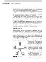
not allowing it to be routed across different networks. To make sure you
understand what is meant by this, view Figure 6.7. Here, you see a network
subdivided by different IP subnets (this will be covered in greater depth in
Chapter 7).
You can see that each local area network (LAN) is connected to each
other via a WAN, using Frame Relay (both of which will be covered in depth
in Chapter 7). The most critical fact here is that all of this logical address-
ing and routing are done at the network layer of the OSI model. Each sub-
net must be unique, and each LAN will need to know how to get to the
other LANs. That’s where the WAN and the routers come in, acting as the
default gateway for your network. Also, you need to understand that logical
addressing (such as the 10.1.1.1 255.255.255.0 address being assigned to
the router on the LAN as the default gateway) is important; it defines how
and where the packets are sent and so on. So, now that you have assigned
the IP address, how does the MAC address tie in? Well, a TCP/IP protocol
called Address Resolution Protocol (ARP) will help map an IP address to a
physical machine address.
The network layer is also responsible for creating a virtual circuit
(a logical connection, not a physical connection) between points or nodes.
A node is a device that has a MAC address, which typically includes
Note
To understand the difference between physical and logical addresses, consider this
analogy: if you buy a house, it has a physical address that identifies exactly where it is
located on the earth, at a specific latitude and longitude. This never changes (unless you
have a mobile home that can be moved from one plot of land to another). This is like the
MAC address on a NIC. Your house also has a logical address assigned to it by the post
office, consisting of a street number and street name. The city can (and occasionally
does) change the names of streets or renumber the houses located on them. This is like
the IP address assigned to a network interface.
The OSI Model 247
computers, printers, and routers. This layer is also responsible for routing,
Layer 3 switching (which is nothing more than a Layer 2 switch with a
Layer 3 router built into it) and the forwarding of packets.
Routing refers to forwarding packets from one network or subnet to
another. Without routing, computers can communicate only with other
computers that are on the same network via ARP broadcasts. Routing makes
it possible for computers to send data through many networks to other
computers that are on the other side of the world. Routing is the key to the
FIGURE 6.7 TCP/IP Networks Subdivided and Connected via Routers.
CHAPTER 6: The OSI Model and Networking Protocols 248
global Internet and is one of the most important duties of the network layer.
Easy to remember, routing is simple to understand. If you start with a LAN
that has the 10.1.1.0 255.255.255.0 network and you wanted to get to the
10.1.2.0 255.255.255.0 network (which has a different network number in
the third octet), you would need a router with a routing table (so it knows
where to send the packet) to get it there.
Finally, the network layer provides additional levels of flow control and
error control. As mentioned earlier, from this point on, the primary methods
of implementing the OSI model architecture involve software rather than
hardware.
Devices that operate at this layer include, most prominently, routers and
Layer 3 switches.
Layer 4: Transport
Layer 4 is the transport layer. As the name implies, it is responsible for
transporting the data from one node to another. It provides transparent
data transfer between nodes and manages the end-to-end flow control, error
detection, and error recovery.
The transport layer protocols initiate contact between host computers
and set up a virtual circuit. The transport protocols on each host computer
verify that the application sending the data is authorized to access the
network and that both ends are ready to initiate the data transfer. When
this synchronization is complete, the data can be sent. As the data is being
transmitted, the transport protocol on each host monitors the data flow and
watches for transport errors. If transport errors are detected, the transport
protocol can provide error recovery.
The functions performed by the transport layer are very important to
network communication. Just as the data link layer provides lower-level
reliability and connection-oriented or connectionless communications,
the transport layer does the same thing at a higher level. In fact, the two
protocols most commonly associated with the transport layer are defined by
their connection state: TCP, which is connection-oriented, whereas UDP,
which is connectionless.
What else does the transport layer do? It handles another aspect of logical
addressing: ports. If you think of a computer’s IP address as analogous to
the street address of a building, you can think of a port as a suite number
or apartment number within that building. It further defines exactly where
the data should go.
A computer might have several network applications running at the
same time: a Web browser sending a request to a Web server for a Web page,
The OSI Model 249
an e-mail client sending and receiving mail, and a file transfer program
uploading or downloading information to and from an FTP server. There
must be some mechanism to determine which incoming data packets
belong to which application, and that’s the function of port numbers. The
FTP protocol used by that program is assigned a particular port, whereas
the Web browser and e-mail clients use different protocols (HTTP and Post
Office Protocol [POP3] or Internet Message Access Protocol [IMAP]) that
have their own assigned ports. Thus the information that is intended for
the Web browser doesn’t go to the e-mail program by mistake. Port numbers
are used by the transport layer protocols (TCP and UDP).
Finally, the transport layer deals with name resolution. Because human
beings prefer to identify computers by names instead of IP addresses (after
all, it’s easier to remember “www.microsoft.com” for Microsoft’s Web
server than “207.46.249.222,” for example), but computers know only
how to interpret numbers (and binary numbers, at that), there must be a
way for names to be matched with numerical addresses so that people and
computers don’t drive one another crazy. Name resolution methods such
as the domain name system (DNS) solve this problem, and they generally
operate at the upper layers of the OSI model.
HEAD OF THE CLASS…
Different Switches for Different Layers
Troubleshooting network problems requires that you
understand which protocols and devices operate at
which layers of the networking model. It’s important
to understand that all switches are not created equal.
There are actually several different types of devices
that are called switches and they operate at different
layers of the OSI model.
Layer 2 switches are sometimes called standard
switches. They operate at the data link layer and func-
tion like sophisticated hubs. When a computer sends
data to a hub, the hub sends it back out on all ports, to
all the connected computers. A switch sends the data
only out the port to which the destination computer
(based on the addressing information in the headers)
is attached. This decreases the amount of unnecessary
traffic on the network and also increases security.
Layer 3 switches operate at the network layer
and are really a specialized type of router. They’re
sometimes called switched routers. Layer 3 switches
use the information in the packet headers to apply
policies, in addition to performing normal routing
functions.
Layer 4 switches operate at the transport layer
(in addition to the lower layers) and can use the port
number information from TCP or User Datagram
Protocol (UDP) headers. They can provide access
control lists (ACLs) to filter traffic for better security
and are able to control bandwidth allocation for load
balancing purposes. Some routers also function as
Layer 4 switches. These devices can help to identify
application layer (Layer 7) protocols, such as capable
Hypertext Transfer Protocol (HTTP), File Transfer
Protocol (FTP), and so on.
CHAPTER 6: The OSI Model and Networking Protocols 250
Layer 5: Session
After the transport layer has established the virtual connection, a communi-
cation session can be established. A communication session occurs between
two processes on two different computers. The session layer is responsible
for establishing, monitoring, and terminating sessions, using the virtual
circuits established by the transport layer.
The session layer is also responsible for putting header information into
data packets to indicate where the message begins and ends. Once header
information is attached to the data packets, the session layer performs
synchronization between the sender’s session layer and the receiver’s
session layer. The use of acknowledgement (ACK) messages helps coordinate
transfer of data at the session layer.
A very important function of the session layer is controlling whether
the communications within a session are sent as full-duplex or half-duplex
messages. Half-duplex communication goes in both directions between
the communicating computers, but information can travel in only one
direction at a time (as with walkie-talkie radio communications, in which
you have to hold down the microphone button to transmit and cannot hear
the person on the other end when you do). With full-duplex communica-
tion, information can be sent in both directions at the same time (as in a
regular telephone conversation, in which both parties can talk and hear one
another at the same time).
HEAD OF THE CLASS…
Connection-Oriented versus Connectionless
What’s the difference between a connection-oriented
and a connectionless protocol? A connection-oriented
protocol such as TCP creates a connection between
the two computers before actually sending the data and
then verifies that the data has reached their destination
by using acknowledgements (messages sent back to
the sending computer from the receiving computer that
acknowledge receipt). Connectionless protocols send the
data and trust that it will reach the proper destination.
Consider an analogy: you need to send a very impor-
tant letter to a business associate, containing valuable
papers that must not get lost along the way. You call
him before mailing the letter, to let him know he should
expect it (establishing the connection). You might even
insure it or send it via certified mail. After a few days
have passed, your friend calls you back to let you know
that he did receive the letter or you get back the return
receipt that you requested (acknowledgement). This is
the way a connection-oriented communication works.
It’s different from mailing a relatively unimportant item,
such as a postcard to a friend when you’re on vacation.
In that case, you just drop it in the mailbox and hope
it gets to the addressee. You don’t expect or require
any acknowledgement. This is like a connectionless
communication.
The OSI Model 251
Although the transport layer establishes a connection between two
machines, the session layer establishes a connection between two processes.
A process is a defined task related to an application. An application may run
many processes simultaneously to accomplish the work of the application.
These processes are small executable files that together do the work
required by the application. You can view the processes running on your
Windows-based computer by pressing CTLALTDEL, selecting Task
Manager, and then clicking the Processes tab. You’ll notice you have far
more processes running than applications since each application typically
runs more than one process at a time.
The session layer, then, is responsible for setting up the connection
between an application process on one computer and an application process
on another computer, after the transport layer has established the connection
between the two machines.
There are many important protocols that operate at the session layer,
including Windows Sockets (the Winsock interface) and NetBIOS (the
Network Basic Input/Output interface).
Layer 6: Presentation
Data translation is the primary activity of Layer 6, the presentation
layer. When data is sent from sender to receiver, the data is translated at
the presentation layer. The sender’s application passes data down to the
presentation layer, where it is put into a common format. When the data
is received on the other end, the presentation layer changes the data from
the common format back into a format that is useable by the application.
Protocol translation, the conversion of data from one protocol to another so
that it can be exchanged between computers that use different platforms or
operating systems, takes place here.
This is the layer at which many gateway services operate. Gateways
are connection points between networks that use different platforms or
Note
Earlier in this chapter, we mentioned multiplexing. Computer communications can be in
half-duplex or full-duplex mode. Simplex, or unidirectional (one-way) communication,
generally, is not used in computer networking. It is the type of communication used for
radio and over-the-air TV broadcasts (many cable television [CATV]) transmissions now
use two-way signaling to allow for interactive TV).
CHAPTER 6: The OSI Model and Networking Protocols 252
applications. Examples include e-mail gateways (which allow for com-
munications between two different e-mail programs using a common
protocol such as Simple Mail Transfer Protocol [SMTP]), Systems Network
Architecture (SNA) gateways (which allow PCs to communicate with
mainframe computers), and gateways that cross platforms or file systems
(for example, allowing Microsoft clients that use the Server Message Block
(SMB) protocol for file sharing to access files on NetWare servers that use
NetWare Core Protocol). Gateways are usually implemented via software,
such as the Gateway Services for NetWare (GSNW). Software redirectors
also operate at this layer.
This layer is also where data compression can take place, to minimize
the actual number of bits that must be transmitted on the network media to
the receiver. Data encryption and decryption take place in the presentation
layer as well.
Layer 7: Application
The application layer is the point at which the user application program
interacts with the network. This layer of the OSI model should not be
confused with the application itself. This is very important to understand
and remember, as they share the same name. Application processes, such as
file transfers or e-mail, are initiated within a user application (for example,
an e-mail program). Then the data created by that process are handed to
the application layer of the networking software. Everything that occurs at
this level is application-specific. File sharing, remote printer access, network
monitoring and management, Remote Procedure Calls (RPCs), and all forms
of electronic messaging occur at this level.
Both FTP (a common way of transferring files across a network) and
Telnet function within the application layer, as do SMTP, POP3, and
IMAP4, all of which are used for sending or receiving e-mail. There are
many other application layer protocols, including HTTP, Network News
Test Day Tip
Although it’s important to understand the details of the OSI model for the exam, you’re
likely to run into a limited number of questions related to the specific layers of the
model. Understanding the basic functions of each layer will help you easily identify
correct answers to the questions you may see on the exam. It is especially important to
remember that, when troubleshooting, you should start with Layer 1 (physical) and work
your way up. A common error among technicians and network administrators is starting
to troubleshoot at Layer 7. Greater detail about troubleshooting with the OSI model can
be found in Chapter 11, “Network Troubleshooting Tools.”
The OSI Model 253
Transfer Protocol (NNTP), and Simple Network Management Protocol
(SNMP).
Be sure to distinguish between the protocols mentioned and applications
that may bear the same names. There are many different FTP programs
made by different software vendors, but all of them use the FTP protocol to
transfer files.
Encapsulation of Data
One last item to cover before we move on to new material is that you should
make sure you understand what encapsulation is and how it works. Notice
that each layer in Figure 6.8 adds a header to the data packet so that by the
time it reaches the physical layer (the last one on the bottom), it is much
longer than when it started at the application layer. When data is received by
the receiving host, the headers are stripped off as the data moves back up the
stack, one layer at a time, by the layer that corresponds to the one that added
it. This means that each layer on the sending computer communicates only
with the layer of the same name on the receiving machine.
The Microsoft Model
Prior to the release of Windows NT 3.1, users who wanted to connect to
a network had to obtain the TCP/IP protocol suite from a third party and
install it. TCP/IP did not come bundled with the software. At times, the
TCP/IP software that was purchased didn’t work well with the operating
system (OS) because it handled various tasks of network communication in
a slightly different way than did the operating system. This sometimes led to
intermittent network problems or time-spent troubleshooting TCP/IP and
operating system interoperability.
With the release of Windows
NT 3.1, TCP/IP was built into
the operating system, providing a
seamless integration of network-
ing functionality in the OS. Since
that time, it has become standard
to provide TCP/IP with the
operating system because many
computers today connect to a net-
work in one form or another.
The Microsoft model as
seen in Figure 6.9 provides a
standard platform for application
developers.
FIGURE 6.8 Data Moving through the OSI Layers.
CHAPTER 6: The OSI Model and Networking Protocols 254
This modular design enables the developer to rely upon the underlying
services of the OS through the use of standard interfaces. (Sound familiar to
the discussion we had earlier on the DoD and OSI models?) These interfaces
provide specific functionality developers can use as building blocks to develop
an application. This makes development time shorter and provides common
interfaces for users, making learning and using new applications easier.
FIGURE 6.9 The Microsoft Model.
The OSI Model 255
Though the Microsoft model is used primarily by programmers, it’s
important to understand the framework we explore, of how TCP/IP works
on a Microsoft Windows-based computer.
Understanding the Function of Boundary Layers
The Microsoft model describes software and hardware components and
the connections between them that facilitate computer networking. This
modular approach both allows and encourages hardware and software
vendors to develop products that work together through the Microsoft
operating system. Boundary layers are interfaces that reside at the boundar-
ies of functionality. They interact with the layer below and the layer above,
providing an interface from one layer to the next.
Within each layer, various components perform the tasks defined at
the layer. A variety of components can provide similar functionality at any
given layer. This modular approach provides flexibility for developers while
providing common interfaces that reduce development time and cost.
A vendor can provide new functionality at any of these layers, knowing their
products will integrate with the other layers to provide seamless network com-
munications. The interfaces defined by Microsoft are the Network Driver Inter-
face Specification (NDIS), Transport Driver Interface (TDI), and the application
program interface (API). Figure 6.9 shows the relationship of these boundary
layers to both the OSI model and to the Microsoft Architecture.
The Windows OS is divided into three primary areas: the User, the
Executive, and the Kernel. The Kernel is the core of the Microsoft operating
system architecture and it manages the most basic operations including
interacting with the hardware abstraction layer that interacts with the
hardware (CPU, memory, etc.). The Kernel also synchronizes activities with
the Executive level, which includes the Input/Output (I/O) Manager and the
Process Manager. The User level interacts with the Executive level; this is
the level at which most applications and user interfaces reside.
the NDIs boundary Layer
The NDIS works at the bottom of the networking architecture and maps to
the data link layer of the OSI model and the Network Interface layer of the
DARPA model. The NDIS layer is the boundary between the physical network
(physical layer of the OSI model) and the higher-level transport protocols. This
layer provides the standardized functions that allow various transport protocols
to use any network device driver that is compatible with the specifications of
this layer, providing both flexibility and reliability to developers. The earliest
versions of NDIS were developed by a Microsoft and 3Com joint effort. Later,
NDIS versions are proprietary to Microsoft operating systems.