CompTIA Network+ Certification Study Guide part 62 pdf
Bạn đang xem bản rút gọn của tài liệu. Xem và tải ngay bản đầy đủ của tài liệu tại đây (139.58 KB, 10 trang )
CHAPTER 12 : Network Troubleshooting Methodology 596
should be local (occurring on the same side of the bridge or switch), and no
more than 20 percent should cross the bridge or switch. For best performance,
ensure that those computers that communicate with one another most often
are on the same side of the bridge or switch. Frequently accessed file or
print servers should be placed on the same side of the bridge or switch as
those
clients that use them most often. Before implementing a bridging or
switching solution, you should carefully analyze the normal flow of network
traffic and try to group nodes so that most communication, and especially
transfer of large amounts of data, takes place without the need to cross the
bridge.
Identifying the Cause of an Infrastructure Problem
One issue that can sometimes occur with bridges and switches is called
looping. This can occur when there is more than one active bridge or switch
on a network. In a loop, when the bridges and switches don’t know the
location of a destination computer, they send the data frame across the bridge
or switch. This results in multiple copies of the same data frame on the
network, causing unnecessary congestion – but it gets even worse than that.
As each device detects the frame sent by the other bridge or switch, it passes
the frame back across to the other side. The frames coming from the other
bridge cause each bridge or switch to make incorrect entries in its routing
table for the destination computer, and this in turn intermittently prevents
the destination computer from receiving data. The problem is intermittent
because the bridges keep resetting the entries in the routing table based on
where the data frames are coming from. This can go on forever in an endless
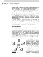
loop, hence the term looping. See Figure 12.5 for an example of how this can
happen.
In the scenario shown in Figure 12.5, if Computer B sends a message
to Computer A, both bridges would detect the data frame. Neither bridge
knows where Computer A is located, so both bridges would transmit the
frame to the other segment. They would put an entry in the routing tables
identifying Computer B as being off the left-side port. Two copies of the data
frame have now been transmitted onto the right-side bridge port. Now each
bridge will also detect the copy of the data frame sent by the other bridge on
the right-side port. They see the source address and think this is Computer
B sending Computer A another frame. They will now pass the frame back
to the left-side port. Assuming Computer B is now on the right-side port,
they change the table to reflect that status. This can go on forever, with
both bridges detecting each other’s transmitted frames and passing them
across, then changing Computer B’s status in the table from the right- to
the left-side port over and over again. When the routing table is incorrectly
Troubleshooting the Data Link Layer 597
set, Computer B will not be able to receive any data. When the table changes
again and Computer B is identified as being on the correct bridge port, it will
be able to receive data, but only until the tables are changed once more. The
problem here is that a bridge looks at the source and destination addresses,
but cannot identify duplicate frames.
This does not mean that you can’t have two bridges on a network. In fact,
redundancy is a good idea, in case one bridge “dies”. So how do you prevent
the looping behavior? The answer is the Spanning Tree Protocol. If your
bridge supports and is configured to use this protocol, it will be able to com-
municate with other bridges on the network. The two bridges will then work
FIGURE 12.5 Looping Can Occur on a Bridged or Switched Network.
CHAPTER 12 : Network Troubleshooting Methodology 598
cooperatively, with one functioning in active mode and the other on standby
unless or until it detects a failure of the first bridge. At that point, the second
bridge will take over passing data frames. With only a single pathway avail-
able at any given time, there is no possibility of a loop.
TROUBLESHOOTING THE NETWORK LAYER
The Network layer of the OSI model is Layer 3, and it houses the addressing
protocol of the TCP/IP protocol suite, IP. The protocols TCP and UDP both
operate at the transport layer, which is Layer 4, and they both rely on IP to
address data packets from the sending to the receiving computer.
As you’ve worked through this guide, you’ve learned that routing takes
place at the network layer, and routing is all about recognizing network and
host IP addresses and mapping out the most efficient way to get from one
address to another.
For instance, let’s assume that you were to take on the job of navigator
on a cross-country automobile trip. Just as TCP and IP, working together,
have different responsibilities, you and the driver could divide the duties
so that the journey goes more smoothly. It’s the driver’s job to get the car
to the destination safely and in one piece, and the navigator’s job to know
where the next stop is along the route. Comparatively, it is TCP’s job to
move the data to its destination safely, whereas it is the function of IP to
know the appropriate next hop along a route to an end destination. If you
were to perform the function of identifying the next stop along the way to
the end destination, you would be performing a function similar to that of
the IP protocol at the network layer.
It is also the job of the navigator to consider factors such as the size of
each thoroughfare, known areas of congestion, and anything else that might
make one route more desirable than another. This is similar to the tasks
given to the network layer within the OSI model. Protocols that exist at
the network later are responsible for finding a path through a network to
the destination computer. They are also responsible for translating logical
addresses. In the case of TCP/IP, the IP addresses assigned to a machine
must be translated into physical addresses. The physical, or MAC address is
burned into a chip on the NIC by its manufacturer.
IP routes messages based on the network number of the destination
address. Every computer has a table of network numbers, known as a routing
table. If there is an entry in the routing table for the destination network ID,
the computer sends it to a gateway address, which represents the first router
Troubleshooting the Network Layer 599
in the path to the destination. A default gateway address is included in the
routing table to send packets to when a specific route to the destination
network ID isn’t found in the routing table. The default gateway must be on
the same network as the source computer. Each gateway or router that the
message must go through on the way to its destination is called a hop. You
might say that a journey of a thousand hops begins with a single step: the
gateway address listed in the routing table for a particular network number.
The network layer can use either static or dynamic routing to find a path
from a source to a destination computer. It’s easy to map out a static route
to a friend’s house that is four blocks away – the path that you take will
likely never change, and it’s a simple one to remember. However, if you’re
trying to get to the home of a relative who lives in the backwoods in another
state, you may need more than a good map. You may need to call ahead and
get directions from someone who has traveled there recently. As networks
become larger and more complex, it becomes more difficult to manually
maintain routing tables. When this happens, you will want to use a dynamic
routing protocol. Dynamic routing protocols automatically update routes on
all routers on the network. The most common dynamic routing protocols
available are the Router Information Protocol (RIP) and the Open Shortest
Path First (OSPF) protocol.
The TCP/IP suite includes several protocols that operate at the net-
work layer of the OSI model, including one of the two major components
of the suite: IP. IP handles addressing and routing at the network Level,
relying on logical IP addresses. It can use packet switching methods to
route different packets, which are all part of the same message, via differ-
ent pathways. It can use dynamic routing protocols to determine the most
efficient routes on a per-packet basis. IP is a connectionless protocol; it
depends on TCP at the transport layer above it to provide a connection,
if necessary. However, it is able to use number sequencing to break down
and reassemble messages, and uses a checksum to perform error checking
on the IP header.
Two additional TCP/IP protocols that operate at the network layer are the
ARP and the Reverse Address Resolution Protocol (RARP). ARP’s job is to
translate logical IP addresses to physical MAC addresses. ARP discovers this
information by way of broadcasts, and keeps a table of IP-to-MAC entries.
Test Day Tip
Remember that routers, whether they are dedicated hardware devices or routing software
running on a Windows server, all operate at the network layer.
CHAPTER 12 : Network Troubleshooting Methodology 600
HEAD OF THE CLASS…
Packet Switching and Circuit Switching –
Deciphering the Terminology
Many people easily confuse the terms packet switch-
ing and circuit switching. Even experienced network
administrators, if they haven’t had much exposure to
the conceptual and hardware sides of WAN technology,
find them a little mysterious. They sound like the same
thing, but they’re not.
Circuit switching technology is something we use
all the time, whether we’re aware of it or not. The public
telephone system (which is formally called PSTN
or Public Switched Telephone Network) is the most
familiar example of switched-circuit communication.
An end-to-end communication link is established when
you place a telephone call, and that same physical path
from one end (your telephone) to the other (Aunt Mary’s
telephone in Boise, Idaho, for example) is maintained
for the duration of that call. The path is reserved until
you break the connection by hanging up.
If you call Aunt Mary again next week, the pathway
(also called the circuit) used may be completely different.
That’s where the switching comes in, and that explains
why sometimes when you talk to Aunt Mary, the con-
nection is clear, while other times there’s so much noise
and static on the line that you have to ask her to repeat
herself when she tells you whose quilt won first prize at
this year’s county fair.
Packet switching is different in that there is no
dedicated pathway or circuit established. It is known as
a connectionless technology for that reason. If you send
data from your computer to your company’s national
headquarters in New York over a packet-switched
network, each individual packet, or chunk of data, can
take a different physical route to get there. Most traffic
sent across the Internet uses packet switching.
Another type of digital packet switching network
called X.25 can also support virtual circuits, in which
a dedicated logical connection is established between
two parties for a certain duration. A permanent virtual
circuit, or PVC, creates an ongoing, dedicated logical
connection between two locations, even though the
physical network connection can be shared by more
than one logical connection.
This table is referred to as the ARP cache. RARP is a similar protocol that does
the opposite of ARP; instead of starting with an IP address and finding the
matching MAC address, it uses the MAC address to find the IP address.
The ICMP also exists at the network layer and is known as a maintenance
protocol. It is invaluable in TCP/IP troubleshooting and it allows two
computers on an IP network to share IP status and error information.
ICMP is used by the ping and tracert utilities that have been discussed in
Chapter 11, as well as the traceroute utility for UNIX and Linux computers.
Computers and routers using IP can report errors and exchange control and
status information via ICMP.
Finally, the last protocol that exists at the network layer is Internet Group
Management Protocol (IGMP). IGMP allows computers on a network such
as the Internet to participate in IP multicasting. A multicast address allows
an application to send a message to a large number of recipients without
requiring the source computer to know the addresses of all the recipients.
Troubleshooting the Network Layer 601
Network routers use IGMP to translate the multicast address into host
addresses. This works because each computer involved in a multicast group
will use IGMP to report its multicast group memberships to the necessary
routers to receive the appropriate multicast messages. For example, if you
sign up for a real-time Webcast from your laptop computer, your laptop will
use IGMP to register with the multicast router that will be transmitting
the Webcast. When the Webcast starts, the Webcast application will send
its information to the multicast router, which will use IGMP to send the
Webcast to any computers who signed up for it (including yours).
Layer 3 Troubleshooting
You’ll spend quite a bit of time troubleshooting at the network layer, because
this is the layer that really governs whether two computers can communicate
with one another. A failure at the network layer can create connectivity issues
where a single client or an entire subnet cannot communicate with another
portion of a network, either because of a physical device failure or because of
some type of misconfiguration.
It is helpful to have documentation of the physical and logical network
design available so that you can understand how traffic should be flowing on
CONFIGURING AND IMPLEMENTING …
The 6to4 Protocol
The Internet Engineering Task force (IETF) has created
a new protocol called 6to4, the purpose of which is
to encapsulate IPv6 packets inside IPv4 packets. This
will allow networks that migrate to IPv6 early to be
able to send their data across the Internet, even if the
Internet Service Providers (ISPs) don’t yet support the
new version of IP.
Many ISPs are now using network address transla-
tion (NAT) to allow for the translation of multiple pri-
vate IP addresses that don’t have to be registered, to a
smaller number of public assigned addresses. For this
reason, many ISPs have not been in a hurry to imple-
ment IPv6 support. Reconfiguring all of their equip-
ment to use IPv6 addresses would be a big project,
requiring a great deal of time and effort. The recent
popularity of NAT devices and software implementa-
tions of NAT (along with inexpensive proxy software) has
taken the edge off of the urgency of upgrading, at least
for some companies. NAT is built into Windows 2000
Server products, and a simple, lighter version of NAT
called Internet Connection Sharing (ICS) is included in
the Windows 2000, Windows 98SE, Windows XP, and
Windows Server 2003 operating systems. Using one
of these operating systems, all of the computers on a
network can access the Internet using just one public
registered IP address.
The new 6to4 Protocol will solve the compatibil-
ity problem for those corporate networks that do wish
to adopt IPv6 sooner rather than later and may make
migration more attractive for others as well. The 6to4
Protocol is installed on a router that serves as a gate-
way from the IPv6 network to the Internet. It works by
automatically assigning a prefix to each IPv6 address,
which identifies it as a 6to4 address. The 6to4 protocol
then establishes a tunnel over IPv6 network.
CHAPTER 12 : Network Troubleshooting Methodology 602
your network, especially when you’re troubleshooting IP connectivity issues
on a large network. This allows you to compare the desired path to the
actual path that the data may be taking. You’ll recall that network routes
are measured in hops, where each hop represents a single router between the
source and destination computer. Because of this, you have the potential for
failure at every hop along the way, and so you may need to test connectivity
at every single hop.
When troubleshooting network layer issues, there are a few common
situations that tend to be the source of most connectivity issues. If a source
computer is trying to send information to a destination computer, and the
source computer’s default gateway does not have a route to the destination,
the packet will never reach the destination computer because the gateway
doesn’t know where to send it. This can happen, not only at the default
gateway, but at every router along the path. There might also be a physical
connectivity issue between the source and destination computers, where
either a router or a network link that’s required to transmit the information
has failed or gone offline. The best tools to check connectivity at the network
layer are ping, tracert, traceroute (fr UNIX/Linux), and pathping (for Windows
2000/2003), which we discussed in Chapter 11.
You should also check for configuration issues on each router along the
path to ensure that nothing has changed or been configured incorrectly.
A common misconfiguration, especially when new routers or network links
are added to a network, is a routing loop, which occurs in this fashion:
A source computer on Network A is trying to reach a destination 1.
computer on Network C. The source computer sends the packet to
its default gateway; let’s call it Router A.
Router A checks its routing table to figure out how to reach 2.
Network C. Router A sees that the next hop to Network C is
Router B. So Router A sends the packet to Router B.
Router B receives the packet that’s intended for Network C. Router 3.
B checks its routing table, and sees that the next hop to Network
C … is Router A. So it sends the packet back to Router A.
I bet you can guess what happens next: Router A receives the 4.
packet that’s intended for Network C. It checks its routing
table, and sends the packet to Router B, which then proceeds to
send it back to Router A, and the process repeats itself until the
time-to-live (TTL) of the packet has been exceeded and the packet
is dropped.
Troubleshooting the Transport Layer 603
The good news is that a routing loop is easy to detect using the tracert or
traceroute command, because you’ll see the path that the packet is taking
bounce back and forth between the same two routers over and over again as
follows:
9 29 ms 29 ms 28 ms p10-0.sjc01.atlas.cogentco.com [154.54.2.1]
10 30 ms 29 ms 40 ms p4-0.sfo01.atlas.cogentco.com [66.28.4.93]
11 29 ms 29 ms 28 ms p10-0.sjc01.atlas.cogentco.com [154.54.2.1]
12 30 ms 29 ms 40 ms p4-0.sfo01.atlas.cogentco.com [66.28.4.93]
13 29 ms 29 ms 28 ms p10-0.sjc01.atlas.cogentco.com [154.54.2.1]
14 30 ms 29 ms 40 ms p4-0.sfo01.atlas.cogentco.com [66.28.4.93]
15 29 ms 29 ms 28 ms p10-0.sjc01.atlas.cogentco.com [154.54.2.1]
16 30 ms 29 ms 40 ms p4-0.sfo01.atlas.cogentco.com [66.28.4.93]
If the connectivity failure is limited to a single workstation, use the
ipconfig command to verify that the IP address, subnet mask, and default
gateway have been configured correctly. You can also use the route command
to verify that the default gateway and other routing table entries are correct
for an individual PC.
Test Day Tip
If all physical links and routers are functioning between a source and destination
computer, but traffic is still not getting through, verify that a packet filter hasn’t been
configured on a router or firewall between the two computers that is preventing traffic
from getting through.
TROUBLESHOOTING THE TRANSPORT LAYER
The transport layer’s main purpose in life is ensuring reliability. The transport
layer must verify that any data sent by one computer arrives at its intended
destination in good condition. It also needs a way to differentiate between
different communications that may be addressed to different applications
that are being served up by the same IP address. This is accomplished
through the use of port numbers.
Thanks to the multitasking capabilities of Windows and other modern
operating systems, you can use more than one network application
simultaneously. For example, you can use your Web browser to access
your company’s homepage at the same time your e-mail software is down-
loading your e-mail. You already know that TCP/IP uses an IP address
CHAPTER 12 : Network Troubleshooting Methodology 604
to identify your computer on the network, and gets the messages to the
correct system, but how does it separate the response to your browser’s
request from your incoming mail when both messages arrive at the same
IP address? This is where ports come in. The two parts of an IP address
that represent the network address and the host address are somewhat
like a street name and an individual street number. In this analogy, the
port number would identify the specific apartment or suite within the
building.
TCP and UDP, the transport layer protocols, assign port numbers to
each application so the data intended for the Web browser in Apartment A
doesn’t get sent to the e-mail program living in Apartment B. The transport
layer uses two types of connection services: connection-oriented and
connectionless. Which type of connection is most appropriate for sending
a particular message depends on whether you are more concerned with
reliability or speed.
In TCP/IP communications, data is sent over the network as a sequence
of datagrams. A datagram is a collection of data sent as a single message.
Each datagram is sent across the network individually.
A connection-oriented protocol such as TCP offers better error control,
but can’t send information as quickly because it needs to confirm that each
datagram has reached its destination successfully. A connectionless protocol
such as UDP, on the other hand, suffers in the reliability department but has
better speed because it doesn’t need to confirm the delivery of any datagrams
that it sends.
The easiest way to differentiate between connection-oriented and
connectionless communications is by comparing it to the different ways you
can send a letter from your local post office. If you need to send an important
report to the manager of your company’s branch office in El Paso, you could
put it in an envelope, affix the required amount of postage, and drop it in
the corner mailbox. This would be the easiest, quickest way to take care of
the task, but you would have no idea whether or when the report reached its
destination, like connectionless services.
On the other hand, you could go to the post office and fill out a card to
send the report via registered, certified mail, with a return receipt requested.
This would cost more and it would take more time and effort on your
part, but it would be a more reliable form of communication. Just like a
connection-oriented protocol, you would get back an acknowledgment when
the package was delivered, showing that it was indeed received by the person
to whom it was addressed.
Troubleshooting the Transport Layer 605
Connection-oriented services establish a connection before sending the
data. This would be as if, before you sent your certified mail, you first got
on the telephone with the El Paso manager and let him know the report
was coming so he could be on the lookout for its arrival. If you’re really
detail-minded (or paranoid), you could even ask that he call you back when
it gets there, and let you know that all the pages are there in sequence and
it wasn’t damaged along the way. You’ve taken pains to make sure that your
communication is as reliable as possible, but at a cost in terms of time to
both you and the intended recipient.
Exam Warning
As a provider of connection-oriented services, TCP first establishes a virtual connection
between the sending and receiving computers. This is done through the use of
acknowledgments and response messages.
Understanding TCP
TCP works on the transport layer of the TCP/IP model, providing connection-
based communication with other IP hosts. When an application passes
data to the transport layer, it is often too much data to transmit in one
packet, so TCP segments the data on the sending side and reassembles it at
the receiving end according to sequence information that is packaged with
the packet. TCP sends acknowledgments to confirm successful delivery
and analyzes each packet according to checksum information to ensure
data integrity.
TCP uses a system of ports to manage communication. Applications
bind to a specific TCP port, and any inbound traffic delivered to that port
will be picked up by the application. This enables multiple applications
on one host to use TCP at the same time and also standardizes the way
a client can connect to a given service on a server. For instance, Telnet’s
standard TCP port is 23, so Telnet clients try to establish connections on
port 23 by default. Port assignments are flexible; that is, you can change
the port a client or server uses for a specific application if needed. Although
Web servers typically use port 80 for Hypertext Transfer Protocol (HTTP)
communication, the Web server application can be bound to a different
port. You should be aware of the default TCP ports that are used by major
applications when you’re troubleshooting network issues at the transport