Friction and Lubrication in Mechanical Design P2 pot
Bạn đang xem bản rút gọn của tài liệu. Xem và tải ngay bản đầy đủ của tài liệu tại đây (993.91 KB, 20 trang )
10
Chapter
I
lubrication theory
[6,
71.
Tower reported the results of a series of experi-
ments intended to determine the best methods to lubricate a railroad journal
bearing. Working with a partial journal bearing in an oil bath, he noticed
and later measured the pressure generated in the oil film.
Tower pointed out that without sufficient lubrication, the bearing oper-
ates in the boundary lubrication regime, whereas with adequate lubrication
the two surfaces are completely separated by an oil film. Petrov
[5]
also
conducted experiments to measure the frictional losses in bearings. He con-
cluded that friction in adequately lubricated bearings is due to the viscous
shearing of the fluid between the two surfaces and that viscosity is the most
important property of the fluid, and not density as previously assumed. He
also formulated the relationship for calculating the frictional resistance in
the fluid film as the product of viscosity, speed, and area, divided by the
thickness of the film.
The observations of Tower and Petrov proved to
be
the turning point in
the history of lubrication. Prior to their work, researchers had concentrated
their efforts on conducting friction drag tests on bearings. From Tower’s
experiments,
it
was realized that an understanding of the pressure generated
during the bearing operation is the key to perceive the mechanism of lubri-
cation. The analysis of his work carried out by Stokes and Reynolds led to a
theoretical explanation of Tower’s experimental results and to the theory of
hydrodynamic lubrication.
In
1886,
Osborne Reynolds published a paper on lubrication theory
[4]
which is derived from the equations of motion, continuity equation, and
Newton’s shear stress-velocity gradient relation. Realizing that the ratio of
the film thickness to the bearing geometry is in the order of 10-3, Reynolds
established the well-known theory using an order-of-magnitude analysis.
The assumptions on which the theory is based can be listed as follows.
The pressure is constant across the thickness of the film.
The radius of curvature of bearing surface is large compared with film
The lubricant behaves as a Newtonian fluid.
Inertia and body forces are small compared with viscous and pressure
There is no slip at the boundaries.
Both bearing surfaces are rigid and elastic deformations are neglected.
thickness.
terms in the equations of motion.
Since then the hydrodynamic theory based on Reynolds’ work has attracted
considerable attention because of its practical importance. Most initial
investigations assumed isoviscous conditions in the film to simplify the ana-
lysis. This assumption provided good correlation with pressure distribution
Introduction
I1
under a given load but generally failed to predict the stiffness and damping
behavior of the bearing.
A
model which predicts bearing performance based on appropriate
thermal boundaries on the stationary and moving surfaces and includes a
pointwise variation of the film viscosity with temperature is generally
referred to as the thermohydrodynamic (THD) model. The THD analyses
in the past three decades have drawn considerable attention to the thermal
aspects of lubrication. Many experimental and theoretical studies have been
undertaken to shed some light on the influence of the energy generated in
the film, and the heat transfer within the film and to the surroundings, on
the generated pressure.
In 1929, McKee and McKee [39] performed a series of experiments on a
journal bearing. They observed that under conditions of high speed, the
viscosity diminished to
a
point where the product of viscosity and rotating
speed is a constant. Barber and Davenport [40] investigated friction in
several journal bearings. The journal center position with respect to the
bearing center was determined by a set of dial indicators. Information on
the load-carrying capacity and film pressure was presented.
In 1946, Fogg [41] found that parallel surface thrust bearings, contrary
to predictions by hydrodynamic theory, are capable of carrying a load. His
experiments demonstrated the ability
of
thrust bearings with parallel sur-
faces to carry loads of almost the same order of magnitude as can be
sustained by tilting pad thrust bearings with the same bearing area. This
observation, known as the Fogg effect, is explained by the concept of the
“thermal wedge,” where the expansion of the fluid as it heats up produces a
distortion of the velocity distribution curves similar to that produced by a
converging surface, developing a load-carrying capacity. Fogg also indi-
cated that this load-carrying ability does not depend on a round inlet
edge nor the thermal distortion
of
the bearing pad. Cameron [42], in his
experiments with rotating disks, suggested that a hydrodynamic pressure is
created in the film between the disks due to the variation of viscosity across
the thickness of the film. Viscoelastic lubricants in journal bearing applica-
tions were studied by Tao and Phillipoff [43]. The non-Newtonian behavior
of viscoelastic liquids causes a flattening in the pressure profile and a shift of
the peak film pressure due to the presence of normal stresses in the lubricant.
Dubois et al. [44] performed an experimental study of friction and eccen-
tricity ratios in a journal bearing lubricated with a non-Newtonian oil. They
found that a non-Newtonian oil shows
a
lower friction than a corresponding
Newtonian fluid under the same operating conditions. However, this
phenomenon did not agree with their analytical work and could not be
explained.
12
Chapter
I
Maximum bearing temperature
is
an important parameter which,
together with the minimum film thickness, constitutes a failure mechanism
in fluid film bearings. Brown and Newman
[45]
reported that for lightly
loaded bearings
of
diameter
60
in. operating under
6000
rpm, failure due
to overheating of the bearing material (babbitt) occurred at about
340°F.
Booser et al.
[46]
observed a babbitt-limiting maximum temperature in the
range
of
266
to
392°F
for large steam turbine journal bearings. They also
formulated a one-dimensional analysis for estimating the maximum
temperature under both laminar and turbulent conditions.
In a study of heat effects in journal bearings, Dowson et al.
[47]
in 1966
conducted a major experimental investigation
of
temperature patterns and
heat balance of steadily loaded journal bearings. Their test apparatus was
capable
of
measuring the pressure distribution, load, speed, lubricant flow
rate, lubricant inlet and outlet temperatures, and temperature distribution
within the stationary bushing and rotating shaft. They found that the heat
flow patterns in the bushing are a combination of both radial flows and a
significant amount
of
circumferential flow traveling from the hot region in
the vicinity
of
the minimum film thickness
to
the cooler region near the
oil
inlet. The test results showed that the cyclic variation in shaft surface tem-
perature is small and the shaft can be treated as an isothermal component.
The experiments also indicated that the axial temperature gradients within
the bushing are negligible.
Viscosity is generally considered
to
be
the single most important prop-
erty of lubricants, therefore, it represents the central parameter in recent
lubricant analyses. By far the easiest approach to the question of viscosity
variation within a fluid film bearing is to adopt a representative or mean
value viscosity. Studies have provided many suggestions for calculations
of
the effective viscosity in a bearing analysis
[48].
When the temperature rise
of the lubricant across the bearing is small, bearing performance calcula-
tions are customarily based on the classical, isoviscous theory. In other
cases, where the temperature rise across the bearing is significant, the
classical theory loses its usefulness
for
performance prediction. One
of
the early applications of the energy equation to hydrodynamic lubrication
was made by Cope
[49]
in
1948.
His model was based on the assumptions
of negligible temperature variation across the film and negligible heat
conduction within the lubrication film as well as into the neighboring
solids. The consequence
of
the second assumption is that both the bearing
and the shaft are isothermal components, and thus all the generated heat is
carried out by the lubricant.
As
indicated in a review paper by Szeri
[50],
the belief, that the classical theory on one hand and Cope’s adiabatic
model on the other, bracket bearing performance in lubrication analysis,
was widely accepted for a while.
A
thermohydrodynamic hypothesis was
Introduction
13
later introduced by Seireg and Ezzat [51] to rationalize their experimental
findings.
An empirical procedure for prediction of the thermohydrodynamic
behavior of the fluid film was proposed in 1973 by Seireg and Ezzat. This
report presented results on the load-carrying capacity of the film from
extensive tests. These tests covered eccentricity ratios ranging from 0.6 to
0.90, pressures of up to 750 psi and speeds of up to 1650 ftlmin. The
empirical procedure applied to bearings submerged in an oil bath as well
as
to
pump-fed bearings where the outer shell is exposed to the atmosphere.
No
significant difference in the speed-pressure characteristics for these two
conditions was observed when the inlet temperature was the same. They
showed that the magnitudes of the load-carrying capacity obtained experi-
mentally may differ considerably from those predicted by the insoviscous
hydrodynamic theory. The isoviscous theory can either underestimate or
overestimate the results depending on the operating conditions.
It
was
observed, however, that the normalized pressure distribution in both the
circumferential and axial directions of the journal bearing are almost iden-
tical to those predicted by the isoviscous hydrodynamic theory. Under all
conditions tested, the magnitude
of
the peak pressure (or the average pres-
sure) in the film is approximately proportional to the square root of the
rotational speed
of
the journal. The same relationship between the peak
pressure and speed was observed by Wang and Seireg
[52]
in a series
of
tests on a reciprocating slider bearing with fixed film geometry.
A
compre-
hensive review of thermal effects in hydrodynamic bearings is given by
Khonsari [53] and deals with both journal and slider bearings.
In 1975, Seireg and
Doshi
[54] studied nonsteady state behavior of the
journal bearing performance. The transient bushing temperature distribu-
tion in journal bearing appears to be similar to the steady-state temperature
distribution. It was also found that the maximum bushing surface tempera-
ture occurs in the vicinity of minimum film thickness. The temperature level
as well as the circumferential temperature variation were found to rise with
an increase of eccentricity ratio and bearing speed. Later, Seireg and
Dandage [55] proposed an empirical thermohydrodynamic procedure to
calculate a modified Sommerfeld number which can be utilized in the stan-
dard formula (based on the isoviscous theory) to calculate eccentricity ratio,
oil flow, frictional loss, and temperature rise, as well as stiffness and damp-
ing coefficients for full journal bearings.
In 1980, Barwell and Lingard [56] measured the temperature distribu-
tion of plain journal bearings, and found that the maximum bearing tem-
perature, which is encountered at the point of minimum film thickness, is the
appropriate value for an estimate of effective viscosity to be used in load
capacity calculation. Tonnesen and Hansen [57] performed an experiment
14
Chapter
1
on a cylindrical fluid film bearing to study the thermal effects on the bearing
performance. Their test bearings were cylindrical and oil was supplied
through either one or two holes or through two-axial grooves, 180" apart.
Experiments were conducted with three types of turbine oils. Both viscosity
and oil inlet geometry were found to have a significant effect on the operat-
ing temperatures. The shaft temperature was found to increase with increas-
ing loads when a high-viscosity lubricant was used. At the end of the paper,
they concluded that even
a
simple geometry bearing exhibits over a broad
range small but consistent discrepancies when correlated with existing
theory. In 1983, Ferron et al. [58] conducted an experiment on
a
finite-length
journal bearing to study the performance of a plain bearing. The pressure
and the temperature distributions on the bearing wall were measured, along
with the eccentricity ratio and the flow rate, for different speeds and loads.
All measurements were performed under steady-state conditions when ther-
mal equilibrium was reached. Good agreement was found with measure-
ments reported for pressure and temperature, but a large discrepancy was
noted between the predicted and measured values of eccentricity ratios. In
1986, Boncompain et al. [59] showed good agreement between their theo-
retical and experimental work on a journal bearing analysis. However, the
measured journal locus and calculated values differ. They concluded that
the temperature gradient across and along the fluid film is the most impor-
tant parameter when evaluating the bearing performance.
1.5
FRICTIONAL RESISTANCE IN ELASTOHYDRODYNAMIC
CONTACTS
In many mechanical systems, load is transmitted through lubricated con-
centrated contacts where rolling and sliding can occur. For such conditions
the pressure is expected to be sufficiently high to cause appreciable deforma-
tion of the contacting bodies and consequently the surface geometry in the
loaded area is a function of the generated pressure. The study of the beha-
vior of the lubricant film with consideration of the change of film geometry
due to the elasticity of the contacting bodies has attracted considerable
attention from tribologists over the last half century. Some of the studies
related to frictional resistance in this elastohydrodynamic (EHD) regime
are briefly reviewed in the following with emphasis on effect of viscosity and
temperature in the film.
Dyson [60] interpreted some of the friction results in terms
of
a model of
viscoelastic liquid. He divided the experimental curves of frictional traction
versus sliding speed into three regions: the linear region, the nonlinear
Introduction
15
(ascending) region, and the thermal (descending) region. At low sliding
speeds a linear relation exists, the slope of which defines a quasi-
Newtonian viscosity, and the behavior is isothermal. At high sliding speeds
the frictional force decreases as sliding speed increases, and this can be
attributed to some extent to the influence of temperature on viscosity. In
the transition region, thermal effects provide a totally inadequate explana-
tion because the observed frictional traction may be several orders of mag-
nitude lower than the calculated values even when temperature effects are
considered.
Because of the high variation
of
pressure and temperature, many para-
meters such as temperature, load, sliding speed, the ratio of sliding speed to
rolling speed, viscosity, and surface roughness have great effects on
frictional traction.
Thermal analysis in concentrated contacts by Crook
[61, 621,
Cheng
[63],
and Dyson
[60]
have shown
a
strong mutual dependence between tem-
perature and friction in
EHD
contacts. Frictional traction is directly gov-
erned by the characteristics of the lubricant film, which, in the case of a
sliding contact, depends strongly on the temperature in the contact. The
temperature field is in turn governed directly by the heating function.
Crook
[61]
studied the friction and the temperature in
oil
films theore-
tically. He used a Newtonian liquid (shear stress proportional to the velocity
gradient in the film) and an exponential relation between viscosity and tem-
perature and pressure. In pure rolling of two disks
it
has been found that
there
is
no temperature rise within the pressure zone; the temperature rise
occurs on the entry side ahead
of
that zone. When sliding is introduced,
it
has
been found that the temperature on the entry side remains small, but
it
does
have
a
very marked influence upon the temperatures within the pressure
zone, for instance, the introduction of
400
cm/sec sliding causes the effective
viscosity to fall in relation to its value in pure rolling by a factor of
50.
It has
also been shown that at high sliding speeds the effective viscosity is largely
independent of the viscosity
of
oil at entry conditions. This fact carries the
important implication that if an oil of higher viscosity is used to give the
surfaces greater protection by virtue
of
a thicker oil film, then there is little
penalty to be paid by way of greater frictional heating, and in fact at high
sliding speeds the frictional traction may be lower with the thicker film. It has
also been found that frictional tractions pass through a maximum as the
sliding is increased. This implies that if the disks were used as a friction
drive and the slip was allowed to exceed that at which the maximum traction
occurs, then a demand for a greater output torque, which would lead to even
greater sliding, would reduce the torque the drive can deliver.
Crook
[62]
conducted an experiment to prove his theory, and found that
the effective viscosity of the oil at the rolling point showed that the variation
16
Chapter
I
of viscosity, both for changes in pressure and in temperature, decreased as
the rolling speed was increased.
Cheng
[63]
studied the thermal EHD of rolling and sliding cylinders
with a more rigorous analysis of temperature by using a two-dimensional
numerical method. The effect of the local pressure-temperature-dependent
viscosity, the compressibility of the lubricant, and the heat from compres-
sion of the lubricant were considered in the analysis.
A
Newtonian liquid
was used. He found that the temperature had major influence on friction
force. A slight change in temperature-viscosity exponent could cause great
changes in friction data. He also compared his theoretical results with
Crook’s
[62]
experimental results and found a high theoretical value at
low sliding speed. Thus he concluded that the assumption of a Newtonian
fluid in the vicinity of the pressure peak might cease to be valid.
One of the most important experimental studies in EHD was carried out
by Johnson and Cameron
[64].
In their experiments they found that at high
sliding speeds the friction coefficient approached a common ceiling, which
was largely independent of contact pressure, rolling speed and disk tempera-
ture. At high loads and sliding speeds variations in rolling speed, disk tem-
perature and contact pressure did not appear to affect the friction
coefficient. Below the ceiling the friction coefficient increased with pressure
and decreased with increasing rolling speed and temperature.
Dowson and Whitaker
[65]
developed a numerical procedure to solve
the EHD problem of rolling and sliding contacts lubricated by a Newtonian
fluid. It was found that sliding caused an increase in the film temperatures
within the zone, and the temperature rise was roughly proportional to the
square
of
the sliding velocity. Thermal effects restrained the coefficient
of
friction from reaching the high values which would occur in sliding contacts
under isothermal conditions.
Plint
[66]
proposed a formula for spherical contacts which relates
the coefficient of friction with the temperature on the central plane of the
contact zone and the radius
of
the contact zone.
There are other parameters which were investigated for their influence
on the frictional resistance in the EHD regime by many tribologists
[67-851.
Such parameters include load, rolling speed, shear rate, surface roughness,
etc. The results of some of these investigations are utilized in Chapter
7
for
developing generalized emperical relationships for predicting the coefficient
of friction in this regime
of
lubrication.
Introduction
REFERENCES
I7
1.
2.
3.
4.
5.
6.
7.
8.
9.
10.
11.
12.
13.
14.
15.
16.
17.
18.
19.
20.
21.
MacCurdy, E., Leonardo da Vinci Notebooks, Jonathan Cape, London,
England, 1938.
Amontons, G., Histoire de 1’AcadCmie Royale des Sciences avec Les Memoires
de Mathematique et de Physique, Paris, 1699.
Coulomb, C. A., Memoires de Mathematique et de Physique de 1’Academie
Royale des Sciences, Paris, 1785.
Reynolds,
O.,
“On the Theory
of
Lubrication and Its Application to Mr.
Beauchamp Tower’s Experiments Including an Experimental Determination
of
Olive Oil,” Phil. Trans.,
1886,
Vol.
177(i), pp.
157-234.
Petrov,
N.
P. “Friction in Machines and the Effect of the Lubricant,” Inzh.
Zh., St. Petersburg, Russia, 1883, Vol.
1,
pp. 71-140;
Vol.
2, pp. 227-279;
Vol.
3,
pp. 377436; Vol. 4, pp. 435-464 (in Russian).
Tower, B., “First Report on Friction Experiments (Friction of Lubricated
Bearings),” Proc. Inst. Mech. Engrs, 1883, pp. 632-659.
Tower, B., “Second Report on Friction Experiments (Experiments on Oil
Pressure in Bearings),” Proc. Inst. Mech. Engrs, 1885, pp. 58-70.
Grubin, A. N., Book No. 30, English Translation DSIR, 1949.
Dowson, D., and Higginson,
G.
R.,
Elastohydrodynamic Lubrication,
Pergamon, New York, NY, 1966.
Dowson,
D.,
History
of
Tribology, Longman, New York, NY, 1979.
Bowden, F. P., and Tabor, D., The Friction and Lubrication of Solids, Oxford
University Press, New York, NY, 1950.
Pinkus,
O.,
“The Reynolds Centennial: A Brief History of the Theory of
Hydrodynamic Lubrication,” ASME J. Tribol., 1987, Vol. 109,
pp.
2-20.
Pinkus,
O.,
Thermal Aspects
of
Fluid Film Tribology, ASME Press, pp. 126-
131, 1990.
Ling,
F.
F., Editor, “Wear Life Prediction in Mechanical Components,”
Industrial Research Institute, New York NY, 1985.
Suzuki,
S.,
Matsuura, T., Uchizawa, M., Yura,
S.,
Shibata,
H.,
and Fujita,
H.,
“Friction and Wear Studies
on
Lubricants and Materials Applicable MEMS,”
Proc. of the IEEE Workshop
on
MicroElectro Mechanical Systems (MEMS),
Nara, Japan, Feb. 1991.
Ghodssi, R., Denton, D. D., Seireg, A. A., and B. Howland, “Rolling Friction
in Linear Microactuators,” JVSA, Aug. 1993.
Moore, A.J., Principles and Applications
of
Tribology, Pergamon Press, New
York, NY, 1975.
Rabinowicz, E., Friction and Wear of Materials, John Wiley
&
Sons, New
York, NY, 1965.
Stevens, J.
S.,
“Molecular Contact,” Phys. Rev., 1899, Vol. 8, pp. 49-56.
Rankin, J.
S.,
“The Elastic Range
of
Friction,” Phil. Mag., 7th Ser., 1926, pp.
806-8 16.
Courtney-Pratt, J.
S.,
and Eisner, E., “The Effect of a Tangential Force on the
Contact of Metallic Bodies,*’ Proc. Roy. Soc. 1957,
Vol.
A238, pp. 529-550.
18
Chapter
1
22.
23.
24.
25.
26.
27.
28.
29.
30.
31.
32.
33.
34.
35.
36.
37.
38.
39.
40.
41.
42.
Seireg, A., and Weiter,
E.
J., “Viscoelastic Behavior of Frictional Hertzian
Contacts Under Ramp-Type Loads,” Proc. Inst. Mech. Engrs, 1966-67, Vol.
181, Pt. 30, pp. 200-206.
Seireg, A. and Weiter, E. J., “Frictional Interface Behavior Under Dynamic
Excitation,’’ Wear, 1963, Vol. 6, pp. 6677.
Seireg, A. and Weiter, E.
J.,
“Behavior of Frictional Hertzian Contacts Under
Impulsive Loading,” Wear, 1965, Vol.
8,
pp. 208-219.
“Designing for Zero Wear
-
Or
a Predictable Minimum,” Prod. Eng., August
Rabinowicz, E., “Variation
of
Friction and Wear
of
Solid Lubricant Films
with Film Thickness,” ASLE Trans., Vol. 10, n.1, 1967, pp. 1-7.
Reynolds,
O.,
Phil. Trans., 1875, p. 166.
Palmgren, A., “Ball and Roller Bearing Engineering,” S.H. Burbank,
Philadelphia, PA, 1945.
Tabor, D., “The Mechanism of Rolling Friction,” Phil. Mag., 1952, Vol. 43,
p.
1066; 1954, Vol. 45, p. 1081.
Hardy, W. B., Collected Scientific Papers, Cambridge University Press,
London, 1936.
Blok, H. “Surface Temperature Under Extreme Pressure Lubrication
Conditions,” Congr. Mondial Petrole, 2me Cogr., Paris, 1937, Vol. 3(4), pp.
471436.
Kelley, B. W.,
“A
New Look at the Scoring Phenomena of Gears,” SAE
Trans., 1953, Vol. 61,
p.
175.
Sharma, J. P., and Cameron, A., “Surface Roughness and Load in Boundary
Lubrication,” ASLE Trans., Vol. 16(4), pp. 258-266.
Nemlekar, P. R., and Cheng,
H.
S.,
“Traction in Rough Elastohydrodynamic
Contacts,” Surface Roughness Effects in Hydrodynamic and Mixed
Lubrication“, The Winter Annual Meeting of ASME, 1980.
Hirst,
W.,
and Stafford, J.
V.,
“Transion Temperatures in Boundary
Lubrication,” Proc. Instn. Mech. Engrs, 1972, Vol. 186( 15/72), 179.
Furey, M.
J.,
and Appeldoorn,
J.
K.,
“The Effect of Lubricant Viscosity on
Metallic Contact and Friction in a Sliding System,” ASLE Trans. 1962, Vol.
5,
Furey, M. J., “Surface Roughness on Metallic Contact and Friction,” ASLE
Trans., 1963, Vol. 6, pp. 49-59.
Eng, B. and Freeman, P., Lubrication and Friction, Pitman, New York,
NY,
1962.
McKee,
S.
A. and McKee, T. R., “Friction of Journal Bearing as Influenced by
Clearance and Length,” ASME Trans., 1929, Vol. 51, pp. 161-171.
Barber,
E.
and Davenport,
C.,
“Investigation of Journal Bearing
Performance,” Penn. State Coll. Eng. Exp. Stat. Bull., 1933, Vol. 27(42).
Fogg, A., “Fluid Film Lubrication of Parallel Thrust Surfaces,’’ Proc. Inst.
Mech. Engrs, 1946, Vol. 155, pp. 49-67.
Cameron, A., “Hydrodynamic Lubrication of Rotating Disk in Pure Sliding,
New Type
of
Oil Film Formation,” J Inst. Petrol., Vol. 37, p. 471.
15, 1966, pp. 41-50.
pp. 149-159.
Introduction
19
43.
44.
45.
46.
47.
48.
49.
50.
51.
52.
53.
54.
55.
56.
57.
58.
59.
Tao, F. and Phillipoff, W., “Hydrodynamic Behavior of Viscoelastic Liquids
in
a Simulated Journal Bearing,” ASLE Trans., 1967, Vol. 10(3), p. 307.
Dubois,
G.,
Ocvrik, F., and Wehe, R., “Study of Effect of a Newtonian Oil on
Friction and Eccentricity Ratio of a Plain Journal Bearing,” NASA Tech.
Note, D-427, 1960.
Brown, T., and Newman, A., “High-speed Highly Loaded Bearings and Their
Development,” Proc. Conf. on Lub. and Wear, Inst. Mech. Engrs., 1957.
Booser et al. “Performance of Large Steam Turbine Journal Bearings,” ASLE
Trans., Vol. 13, n.4, Oct. 1970, pp. 262-268. Also, “Maximum Temperature for
Hydrodynamic Bearings Under Steady Load,” Lubric. Eng., Vol. 26, n.7, July
1970, pp. 226-235.
Dowson, D., Hudson, J., Hunter, B., and March, C., “An Experimental
Investigation of the Thermal Equilibrium of Steadily Loaded Journal
Bearings,” Proc. Inst. Mech. Engrs, 1966-67, Vol. 101, 3B.
Cameron, A., The Principles of Lubrication, Longmans Green
&
Co., London,
England, 1966.
Cope, W., “The Hydrodynamic Theory of Film Lubrication,” Proc. Roy. Soc.,
Szeri, A.
Z.,
“Some Extensions of the Lubrication Theory of Osborne
Reynolds,” J. of Tribol., 1987, pp. 21-36.
Seireg, A. and Ewat,
H.,
“Thermohydrodynamic Phenomena
in
Fluid Film
Lubrication,” J. Lubr. Technol., 1973, pp. 187-194.
Wang, N.
Z.
and Seireg, A., Experimental Investigation
in
the Performance of
the Thermohydrodynamic Lubrication of Reciprocating Slider Bearing, ASLE
paper
No.
87-AM-3A-3, 1987.
Khonsari, M. M., “A Review of Thermal Effects in Hydrodynamic Bearings,
Part
I:
Slider and Thrust Bearings,” ASLE Trans., 1986, Vol. 30, pp. 19-25.
Seireg, A., and Doshi,
R.
C., “Temperature Distribution in the Bush of Journal
Bearings During Natural Heating and Cooling,” Proceedings of the JSLE-
ASLE International Lubrication Conference, Tokyo, 1975, pp. 194-201.
Seireg, A., and Dandage
S., “Empirical Design Procedure for the
Thermohydrodynamic Behavior of Journal Bearings,” ASME J. Lubr.
Technol., 1982, pp. 135-148.
Barwell, F.T., and Lingard,
S., “The Thermal Equilibrium of Plain Journal
Bearings,” Proceedings of the 6th Leeds-Lyon Symposium on Tribology,
Dowson, D. et al., Editors, 1980, pp. 24-33.
Tonnesen, J., and Hansen, P.
K.,
“Some Experiments on the Steady State
Characteristics of a Cylinderical Fluid-Film Bearing Considering Thermal
Effects,” ASME J. Lubr. Technol., 1981, Vol. 103, pp. 107-1 14.
Ferron, J., Frene, J., and Boncompain,
R.,
“A Study
of
the
Thermohydrodynamic Performance of a Plain Journal Bearing, Comparison
Between Theory and Experiments,” ASME J. Lubr. Technol., 1983, Vol.
105,
pp. 422428.
Boncompain, R., Fillon, M., and Frene, J., “Analysis of Thermal Effects
in
Hydrodynamic Bearings,” J. Tribol., 1986, Vol.
108,
pp. 219-224.
1948, Vol. A197, pp. 201-216.
20
Chapter
I
60.
61.
62.
63.
64.
65.
66.
67.
68.
69.
70.
71.
72.
73.
74.
75.
76.
Dyson, A., “Frictional Traction and Lubricant Rheology in
Elastohydrodynamic Lubrication,” Phil. Trans. Roy.
Soc.,
Lond.,
1970,
Vol.
Crook, A. W., “The Lubrication of Rollers,” Phil. Trans. Roy. Soc., Lond.,
1961,
Vol.
A254,
p.
237.
Crook,
A.
W., “The Lubrication of Rollers,” Phil. Trans. Roy. Soc., Lond.,
1963,
Vol.
A255,
p.
281.
Cheng, H.S., “A Refined Solution to the Thermal Elastohydrodynamic
Lubrication of Rolling and Sliding Cylinders,”
ASLE
Trans.,
1965,
Vol.
8,
pp.
397410.
Johnson,
K.
L., and Cameron, R., “Shear Behavior of Elastohydrodynamic Oil
Films at High Rolling Contact Pressures,” Proc. Inst. Mech. Engrs,
1967-68,
Vol.
182,
Pt.
1,
No.
14.
Dowson, D., and Whitaker, A. V.,
“A
Numerical Procedure for the Solution of
the Elastohydrodynamic Problem of Rolling and Sliding Contacts Lubricated
by a Newtonian Fluid,” Proc. Inst. Mech. Engrs,
196546,
Vol.
180,
Pt.
3B,
Plint, M.
A.,
“Traction in Elastohydrodynamic Contacts,” Proc. Inst. Mech.
Engrs,
1967-68,
Vol.
182,
Pt.
1,
No.
14,
p.
300.
O’Donoghue,
J.
P., and Cameron,
A.,
“Friction and Temperature in Rolling
Sliding Contacts,” ASLE Trans.,
1966,
Vol.
9,
pp.
186-194.
Benedict, G.
H.,
and Kelley, B. W., “Instaneous Coefficients of Gear Tooth
Friction,” ASLE Trans.,
1961,
Vol.
4,
pp.
59-70.
Misharin,
J.
A., “Influence
of
the Friction Conditions on the Magnitude of the
Friction Coefficient in the Case of Rolling with Sliding,” International
Conference on Gearing, Proceedings, Sept.
1958.
Hirst, W
.,
and Moore, A.
J.,
“Non-Newtonian Behavior in Elasto-hydrody-
namic Lubrication,” Proc. Roy. Soc.,
1974,
Vol.
A337,
pp.
101-121.
Johnson,
K.
L.,
and Tevaarwerk, J. L., “Shear Behavior of
Elastohydrodynamic Oil Films,” Proc. Roy. Soc.,
1977,
Vol.
A356,
pp.
Conry, T. F., Johnson,
K.
L., and Owen, S., “Viscosity in the Thermal Regime
of Elastohydrodynamic Traction,” 6th Lubrication Symposium, Lyon, Sept.,
1979.
Trachman,
E.
G., and Cheng,
H.
S.,
“Thermal and Non-Newtonian Effects on
Traction in Elastohydrodynamic Contacts,” Elastohydrodynamic Lubrication,
1972
Symposium, p.
142.
Trachman,
E.
G.,
and Cheng,
H.
S., “Traction in Elastohydrodynamic Line
Contacts for Two Synthesized Hydrocarbon Fluids,” ASLE Trans.,
19?,
Vol.
Winer,
W.
O.,
“Regimes
of
Traction
in
Concentrated Contact Lubrication,”
Trans. ASME,
1982,
Vol.
104,
p.
382.
Sasaki, T., Okamura,
K.,
and Isogal,
R.,
“Fundamental Research on Gear
Lubrication,” Bull. JSME,
1961,
Vol.
4(14),
p.
382.
266(
1
170),
pp.
1-33.
p.
57.
2 15-236.
17(4),
pp.
271-279.
Introduction
21
77.
78.
79.
80.
81.
82.
83.
84.
85.
Sasaki, T. Okamura,
K.
Konishi, T., and Nishizawa, Y. “Fundamental
Research on Gear Lubrication,” Bull. JSME, 1962, Vol.
5(
19), p.
561.
Drozdov, Y. N., and Gavrikov,
Y.
A., “Friction and Scoring Under the
Conditions of Simultaneous Rolling and Sliding
of
Bodies,” Wear, 1968,
Vol. 11, p. 291.
Kelley, B. W., and Lemaski, A.J., “Lubrication
of
Involute Gearing,” Proc.
Inst. Mech. Engrs, 1967-68, Vol. 182, Pt. 3A, p. 173.
Dowson, D., “Elastohydrodynamic Lubrication,” Interdisciplinary Approach
to the Lubrication of Concentrated Contacts, Special Publication No. NASA-
SP-237, National Aeronautics and Space Administration, Washington, D.C.,
1970, p.
34.
Wilson, W.
R.
D., and Sheu,
S.,
“Effect
of
Inlet Shear Heating Due to Sliding
on EHD Film Thickness,” ASME J. Lubr. Technol., Apr. 1983, Vol.
105,
p. 187.
Greenwood, J. A., and Tripp, J. H., “The Elastic Contact of Rough Spheres,”
J. Appl. Mech., March 1967, p. 153.
Lindberg, R. A., “Processes and Materials
of
Manufacture,” Allyn and Bacon,
1977, pp. 628-637.
“Wear Control Handbook”, ASME, 1980.
Szeri, A.
Z.,
Tribology: Friction, Lubrication and Wear, Hemisphere, New
York, NY, 1980.
2
The Contact Between Smooth Surfaces
2.1
INTRODUCTION
It is well known that no surface, natural or manufactured, is perfectly
smooth. Nonetheless the idealized case of elastic bodies with smooth sur-
faces is considered in this chapter as the theoretical reference for the contact
between rough surfaces. The latter will be discussed in Chapter
4
and used
as the basis for evaluating the frictional resistance.
The equations governing the pressure distribution due to normal loads
are given without detailed derivations. Readers interested in detailed deriva-
tions can find them in some
of
the books and publications given in the
references at the end of the chapter
[l-391.
2.2
DESIGN RELATIONSHIPS FOR
ELASTIC
BODIES IN
CONTACT
Case
1
:
Concentrated Normal Load on the Boundary
of
a Semi-Infinite
Solid
The fundamental problem in the field of surface mechanics is that
of
a
concentrated, normal force
P
acting on the boundary
of
a semi-infinite
body as shown in Fig. 2.1. The solution of the problem was given by
Boussinesq
[I]
as:
22
The Contact Between Smooth Surfaces
23
2
Figure
2.1
Concentrated load on a semi-infinite elastic solid.
a,
=
horizontal stress at any point
I
=
P((1
2n
-
2v)[$
-
z
v2
(E
2n
~3(,2~2)-5/2)-”~]
-
3r2Z(r2
+
22)-5/2
az
=
vertical stress at any point
-
3p
23(,.2~2)-5/2
2n
rrz
=
shear stress at any point
-
-_
3p
,z2(,2
+
z2)-5/2
2n
where
v
=
Poisson’s ratio
The resultant principal stress passes through the origin and has a magnitude:
3P
3P
=
4-
=
249
+
22)
-
2nd2
The displacements produced in the semi-infinite solid can be calculated
from:
24
Chapter
2
U
=
horizontal displacement
and
w
=
vertical displacement
where
E
=
elastic modulus
At
the surface where
2
=
0,
the equations for the displacements become:
P(l
-
2)
(tt’)Z,0
=
____
(1
-
2u)(l
+
u)P
(&=0
=
-
2n
Er nEr
which increase without limit as
Y
approaches zero. Finite values, however,
can be obtained by replacing the concentrated load by a statically equivalent
distributed load over a small hemispherical surface at the origin.
Case
2:
Uniform Pressure over a Circular Area on the Surface of a
Semi-Infinite Solid
The solution for this case can be obtained from the solution for the con-
centrated load by superposition. When a uniform pressure
q
is distributed
over a circular area of radius
a
(as shown in Fig.
2.2)
the stresses and
deflections are found to be:
(w)~=(,
=
deflection at the boundary
of
the loaded circle
-
4(
1
-
u2)qa
-
JrE
(w)~=”
=
deflection at the center
of
the loaded circle
-
2(
1
-
u2)qa
-
E
(oZ)r=O
=
vertical stress at any point on the Z-axis
(a2
+
z*)3/2
z3
1
-4
-I+
-(
The Contact Between Smooth Surfaces
25
(I?
Figure
2.2
Uniform pressure on a circular area.
=
horizontal stress at any point
on
the Z-axis
1
(t)r=O
=
5
(or
-
oz)r=o
=
maximum shear stress at any point on the Z-axis
From the above equation
it
can be
shown
that the maximum combined
shear stress occurs at
a
point
given
by:
and its value is:
26
Chapter
2
Case
3:
Uniform Pressure over
a
Rectangular Area on the Surface of
a
Semi-Infinite
Solid
In this case (Fig. 2.3) the average deflection under the uniform pressure
q
is
calculated from:
W,,e
=
k(1
-
u2)
;
.JA
where
A
=
area
of
rectangle
k
=
factor dependent
on
the ratio
b/a
as
shown
in
Table
2.1
It should be noted that the maximum deflection occurs at the center of the
rectangle and the minimum deflection occurs at the corners. For the case
of
a square area
(6
=
a)
the maximum and minimum deflections are given by:
Figure
2.3
Uniform
pressure over a rectangular area.
The Contact Between Smooth Surfaces
Table
2.1
Values
of
Factor
k
1
1.5
2
3
5
10
100
0.95
0.94
0.92
0.88
0.82
0.71
0.37
27
Case
4:
A
Rigid Circular Cylinder Pressed Against a Semi-Infinite Solid
In this case, which is shown in
Fig.
2.4,
the displacement
of
the rigid cylinder
is calculated from:
P(1
-
”*)
w=-
2aE
P
Figure
2.4
Rigid cylinder over a semi-infinite elastic solid.
28
Chapter
2
where
p
=
total load
on
the cylinder
a
=
radius
of
the cylinder
The pressure distribution under the cylinder is given by
which indicates that the maximum pressure occurs at the boundary
(Y
=
a)
where localized yielding is expected. The minimum pressure occurs at the
center
of
the contact area
(r
=
0)
and has half the value
of
the average
pressure.
Case
5:
Two
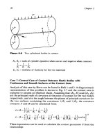
Spherical Bodies in Contact
In this case (Fig.
2.5)
the area of contact
is
circular with radius
a
given by
a
=
0.88
/:
R,
Figure
2.5
Spherical bodies in contact.
The
Contact
Betwven
Smooth
Surfaces
assuming a Poisson’s ratio
U
=
0.3
and the pressure distribution over this
29
area
is:
The radial tensile stress and maximum combined shear stress at the bound-
ary
of
the contact area can be calculated as:
where
P
=
total load
111
_-
+-
E,
El
E2
E,,
E2
=
modulus
of
elasticity for the two materials
Case
6:
Two
Cylindrical Bodies in Contact
The area
of
contact in this case (Fig.
2.6)
is
a rectangle with width
b
and
length equal to the length
of
the cylinders. The design relationships in this
case are:
q
=
pressure
on
the
area of contact
where
P’
=
load
per
unit length of the cylinders
111
R, RI R2
_
-
+-
