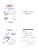
Aircraft Flight Dynamics Robert F. Stengel Lecture5 Configuration Aerodynamics 2.
Bạn đang xem bản rút gọn của tài liệu. Xem và tải ngay bản đầy đủ của tài liệu tại đây (2.36 MB, 20 trang )
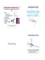
Aerodynamic Drag
"
Configuration Aerodynamics - 2
Robert Stengel, Aircraft Flight Dynamics, MAE 331,
2012
!
! Drag"
! Induced drag"
! Compressibility effects"
! P-51 example"
! Newtonian Flow"
! Moments"
! Effects of Sideslip
Angle"
1 2
2 1
ρV S ≈ C D0 + ε C L ρV 2 S
2
2
2 1
+ ε C Lo + C Lα α ( ρV 2 S
*2
)
(
Drag = C D
≈ %C D0
'
&
(
)
)
Copyright 2012 by Robert Stengel. All rights reserved. For educational use only.
!
/>!
/>!
Induced Drag of a Wing
"
Induced Drag
•
Lift produces downwash (angle proportional to lift)"
– Downwash rotates local velocity vector CW in figure"
– Lift is perpendicular to velocity vector"
– Axial component of rotated lift induces drag"
Spitfire!
Induced Drag
of a Wing"
C Di = C Li sin α i ≈ (C L0 + C Lα α ) sin α i
2
≈ (C L0 + C Lα α ) α i ≡ ε C L
≡
2
C 2 (1+ δ )
CL
= L
π eAR
π AR
where
e = Oswald efficiency factor = 1
for elliptical distribution
δ = departure from ideal elliptical lift distribution
Wing Design Parameters"
Straight, Swept, and
Tapered Wings
"
• Straight at the
quarter chord"
• Swept at the
quarter chord"
• Progression of
separated flow
from trailing
edge with
increasing angle
of attack"
Taper Ratio Effects
"
• Planform"
–
–
–
–
–
–
Aspect ratio"
Sweep"
Taper"
Complex geometries"
Shape at root"
Shape at tip"
• Chord section"
•
– Airfoils"
– Twist"
• Movable surfaces"
– Leading- and trailing-edge devices"
– Ailerons"
– Spoilers"
• Interfaces"
– Fuselage"
– Powerplants"
– Dihedral angle"
Taper makes lift
distribution more elliptical"
– λ ~ 0.45 is best"
– L/D effect (phugoid)"
•
•
•
Tip stall (pitch up)"
Bending stress"
Roll Damping"
Secondary Wing Structures
"
Airfoil Effects
"
• Vortex generators, fences, vortilons,
notched or dog-toothed wing leading edges"
• Camber increases zero-α lift
coefficient"
• Thickness"
– Boundary layer control"
– Maintain attached flow with increasing α!
– Avoid tip stall"
– increases α for stall and
softens the stall break"
– reduces subsonic drag "
– increases transonic drag "
– causes abrupt pitching
moment variation (more to
follow)"
McDonnell-Douglas F-4!
LTV F-8!
• Profile design "
– can reduce c.p. (static
margin) variation with α!
– affects leading-edge and
trailing-edge flow separation"
Sukhoi Su-22!
Leading-Edge Extensions
"
• Strakes or leading edge extensions"
– Maintain lift at high α!
– Reduce c.p. shift at high Mach number"
McDonnell Douglas F-18!
General Dynamics F-16!
Wingtip Design
"
•
•
•
Winglets, rake, and Hoerner tip reduce induced drag by
controlling the tip vortices"
End plate, wingtip fence straightens flow, increasing apparent
aspect ratio (L/D)"
Chamfer produces favorable roll w/ sideslip"
Boeing 747-400!
Airbus A319!
Boeing P-8A!
Yankee AA-1!
Design for Satisfactory Stalls
"
•
•
•
•
•
•
Marked by noticeable, uncommanded
changes in pitch, yaw, or roll and/or
by a marked increase in buffet"
Stall must be detectable"
Aircraft must pitch down when it
occurs"
Up to the stall break, ailerons and
rudder should operate properly"
Inboard stall strips to prevent tip stall
and loss of roll control before the stall"
Strakes for improved high-α flight"
Spanwise Lift Distribution
of 3-D (Trapezoidal) Wings
"
Straight Wings (@ 1/4 chord)
"
(McCormick)
"
TR = taper ratio, λ
!
•
Spanwise Lift Distribution
of 3-D Wings
"
For some taper ratio between 0.35 and 1,
lift distribution is nearly elliptical"
Wing Twist Effects
"
• Washout twist"
C L2− D (y)c(y)
C L3− D c
Straight and Swept Wings
"
(NASA SP-367)
"
• Wing does not
have to have a
geometrically
elliptical planform
to have a nearly
elliptical lift
distribution"
• Sweep moves lift
distribution
toward tips"
– reduces tip angle of
attack"
– typical value: 2° - 4°"
– changes lift distribution
(interplay with taper ratio)
"
– reduces likelihood of tip
stall; allows stall to begin
at the wing root"
• separation burble
produces buffet at tail
surface, warning of stall"
– improves aileron
effectiveness at high α"
Clδ A
Induced Drag Factor, δ
!
C Di =
2
C L (1 + δ )
π AR
Oswald Efficiency Factor, e
!
C Di =
2
CL
π eAR
• Approximation for e (Pamadi, p. 390)"
• Graph for δ
(McCormick, p. 172)"
e≈
1.1C Lα
RC Lα + (1 − R)π AR
where
R = 0.0004κ 3 − 0.008κ 2 + 0.05κ + 0.86
Lower AR!
κ=
P-51 Mustang
"
AR λ
cos Λ LE
P-51 Mustang Example
"
Wing Span = 37 ft (9.83 m)
Wing Area = 235 ft (21.83 m 2 )
Loaded Weight = 9, 200 lb (3, 465 kg)
Maximum Power = 1, 720 hp (1, 282 kW )
C Do = 0.0163
AR = 5.83
λ = 0.5
/>
C Lα =
π AR
2
)
# AR & ,
+1 + 1 + %
( .
$ 2 ' .
+
*
e = 0.947
δ = 0.0557
ε = 0.0576
= 4.49 per rad (wing only)
2
C Di = ε C L =
2
C 2 (1 + δ )
CL
= L
π eAR
π AR
/>
Drag Due to
Pressure Differential"
C Dbase = C pressurebase Sbase
Mach Number Effects
<
2 # Sbase &
%
(
γM 2 $ S '
C Dwave ≈
Prandtl
factor
"
≈
1− M 2
C Dcompressible
M 2 −1
C DM ≈ 2
M 2 −1
Air Compressibility Effect
"
Lockheed P-38!
•
•
Drag rises due to pressure
increase across a shock wave"
Subsonic flow"
Transonic flow"
– Airspeed is less than sonic at
some points, greater than sonic
elsewhere"
•
Supersonic flow"
– Local airspeed is greater than
sonic virtually everywhere"
0.029
Sbase
S
S
C friction wet
Sbase
( M < 1)
( M < 1) [ Hoerner ]
Blunt base
pressure drag
"
γ = specific heat ratio)
“The Sonic Barrier”!
( M > 1)
( M > 1)
Effect of Chord
Thickness on Wing
Pressure Drag
"
Lockheed F-104!
• Thinner chord sections lead to higher Mcrit,
or drag-divergence Mach number"
– Local airspeed is less than sonic
(i.e., speed of sound)
everywhere"
•
≈
( M > 2,
C Dincompressible
≈
Shock Waves in!
Supersonic Flow!
S
•
Critical Mach number"
– Mach number at which local
flow first becomes sonic"
– Onset of drag-divergence"
– Mcrit ~ 0.7 to 0.85"
Air Compressibility
Effect on Wing Drag"
Pressure Drag on Wing
Depends on Sweep Angle
Sonic Booms"
/>
Transonic!
"
Sweep Angle!
Effect on Wing Drag!
Supersonic!
Subsonic!
Incompressible!
Talay, NASA SP-367!
M critswept =
Transonic Drag Rise and the Area Rule
"
• Richard Whitcomb (NASA Langley) and Wallace Hayes (Princeton)
"
• YF-102A (left) could not break the speed of sound in level flight;
F-102A (right) could"
M critunswept
cos Λ
Transonic Drag Rise and the Area Rule
"
• Cross-sectional area of the total configuration should gradually
increase and decrease to minimize transonic drag"
Talay, NASA SP-367!
Sears-Haack Body!
/>
Supercritical
Wing
"
NASA Supercritical !
Wing F-8!
Airbus A320!
Supersonic Biplane
"
• Concept of Adolf Busemann
(1935)"
• Richard Whitcomb s supercritical airfoil "
•
– Wing upper surface flattened to increase Mcrit"
– Wing thickness can be restored"
Shock wave cancellation at
one specific Mach number"
2-D wing"
•
• Important for structural efficiency, fuel storage, etc."
/>
• Kazuhiro Kusunose et al ,
Tohoku U (PAS, 47, 2011,
53-87)"
(–)"
•
•
(+)"
•
Adjustable flaps"
Tapered, variably spaced
3-D wings"
Fuselage added"
Pressure Distribution on
Supercritical Airfoil ~ Section Lift!
Supersonic Transport Concept
"
Large Angle Variations in Subsonic
Drag Coefficient (0° < α < 90°)
"
• Rui Hu, Qiqi Wang, Antony Jameson, Stanford,
MIT, AIAA-2011-1248"
•
•
Optimization of biplane aerodynamics"
Sketch of possible configuration"
•
•
All wing drag coefficients converge to Newtonian-like values
at high angle of attack"
Low-AR wing has less drag than high-AR wing at given α!
Lift-to-Drag Ratio vs.
Angle of Attack
"
Lift vs. Drag for Large Variation in
Angle-of-Attack (0° < α < 90°)"
• L/D is an important performance metric for aircraft"
• High-AR wing has best overall L/D"
• Low-AR wing has best L/D at intermediate angle of attack"
Subsonic Lift-Drag Polar"
L CL q S CL
=
=
D CD q S CD
•
•
Low-AR wing has less drag than high-AR wing, but less lift as well"
High-AR wing has the best overall L/D"
€
Lift-Drag Polar for a
Typical Bizjet
"
• Lift-Drag Polar: Cross-plot of CL(α) vs. CD(α)"
Note different scaling
for lift and drag!
• L/D equals slope of line
drawn from the origin"
– Single maximum for a
given polar"
– Two solutions for lower
L/D (high and low
airspeed)"
Newtonian Flow and
High-Angle-of-Attack
Lift and Drag
Newtonian Flow
"
Newtonian Flow"
• No circulation"
• Cookie-cutter
flow"
• Equal pressure
across bottom of
the flat plate"
Normal Force =
! Mass flow rate $
#
& (Change in velocity ) ( Projected Area ) ( Angle between plate and velocity )
" Unit area %
"
N = ( ρV ) (V ) ( S sin α ) (sin α ) Lift and drag coefficients
= ( ρV 2 ) ( S sin 2 α )
Normal Force =
! Mass flow rate $
#
& ( Change in velocity ) ( Projected Area ) ( Angle between plate and velocity )
" Unit area %
Newtonian Lift and Drag Coefficients
"
Lift = N cos α
#1
&
= ( 2sin 2 α ) % ρV 2 ( S
$2
'
#1
&
≡ C N % ρV 2 ( S = C N qS
$2
'
C L = ( 2sin 2 α ) cos α
Drag = N sin α
C D = 2sin 3 α
Application of Newtonian Flow
"
• Hypersonic flow (M ~> 5)"
Space Shuttle in!
Supersonic Flow!
– Shock wave close to surface
(thin shock layer), merging with
the boundary layer"
– Flow is ~ parallel to the surface"
– Separated upper surface flow"
C L = ( 2sin 2 α ) cos α
• All Mach numbers at
high angle of attack"
C D = 2sin 3 α
– Separated flow on upper
(leeward) surfaces"
High-Angle-ofAttack Research
Vehicle (F-18)!
Airplane Forces and Moments
Resolved into Body Axes
"
Force Vector"
Moments of the
Airplane
! X
# B
f B = # YB
#
" ZB
$
&
&
&
%
Moment Vector"
! L
# B
mB = # M B
#
" NB
Incremental
Moment Produced
By Force
Distribution
"
i
k
x
y
z
fx
r×f =
j
fy
Aerodynamic Force
and Moment Vectors
of the Airplane
"
! f $
! X
# x &
# B
# fy & dx dy dz = # YB
fB = ∫
Surface
#
&
#
#
&
" ZB
" fz %
$
&
&
&
%
fz
#
% ( yfz − zfy )
m = % ( zfx − xfz )
%
% ( xf − yf )
y
x
$
= ( yfz − zfy ) i + ( zfx − xfz ) j + ( xfy − yfx ) k
&
# 0 −z y & # fx &
(
%
(
( = rf = % z 0 −x ( % f (
%
( y
(
% −y x 0 ( % f (
(
'$ z '
$
%
(
'
$
&
&
&
%
"
$ ( yfz − zfy )
$ zf − xf
mB = ∫
( x z)
Surface $
$ ( xf − yf )
y
x
#
%
" L
'
$ B
' dx dy dz =$ M
B
'
$
NB
'
#
&
%
'
'
'
&
Tail Design
Effects"
•
•
Horizontal Tail Location and Size
!
•
•
•
•
•
Aerodynamics
analogous to those of
the wing"
Longitudinal stability"
– Horizontal stabilizer"
– Short period natural
frequency and damping"
•
15-30% of wing area"
~ wing semi-span behind the c.m."
Must trim neutrally stable airplane at maximum lift in ground effect"
Effect on short period mode"
Horizontal Tail Volume: Typical value = 0.48"
Lockheed Martin F-35!
North American F-86!
Directional stability"
– Vertical stabilizer (fin)"
•
•
•
•
•
Ventral fins"
Strakes"
Leading-edge extensions"
Multiple surfaces"
Butterfly (V) tail"
– Dutch roll natural
frequency and damping"
•
•
VH =
Stall or spin prevention/
recovery"
Avoid rudder lock (TBD)!
Cmα ,Cmq ,Cmα ,Cnβ ,Cnr ,Cnβ
Sht lht
S c
Vertical Tail Location and Size
!
• Analogous to horizontal tail volume"
• Effect on Dutch roll mode"
• Powerful rudder for spin recovery"
– Full-length rudder located behind the elevator"
– High horizontal tail so as not to block the flow over the rudder"
• Vertical Tail Volume: Typical value = 0.18"
Curtiss SB2C!
Piper Tomahawk!
VV =
Svt lvt
S b
Pitching Moment
of the Airplane
Pitching Moment
"
•
Pressure and shear stress differentials times moment arms integrate
over the airplane surface to produce a net pitching moment"
Center of mass establishes the moment arm center"
•
Pitching Moment
"
• Distributed effects can be aggregated
to local centers of pressure"
Body - Axis Pitching Moment = M B
=−
∫∫
#Δpz ( x, y ) + Δsz ( x, y )%( x − xcm ) dx dy
$
&
surface
+
∫∫
#Δpx ( y, z ) + Δsx ( y, z )% Δpx ( z − zcm ) dy dz
$
&
surface
I
M B ≈ −∑ Z i ( xi − x cm )
i=1
I
+ ∑ Xi ( zi − zcm ) + Interference Effects + Pure Couples
i=1
Pure Couple
"
• Net force = 0" • Net moment ≠ 0"
Rockets!
Cambered Lifting Surface!
Net Center of Pressure"
• Local centers of pressure can be aggregated
at a net center of pressure (or neutral point)
along the body x axis"
xcpnet
•
•
•
Cross-sectional area, A!
x positive to the right"
At small α!
– Positive lift with dA/dx > 0"
– Negative lift with dA/dx < 0"
Fuselage!
!x C
#
"( cp n )wing + ( xcpCn ) fuselage + ( xcpCn )tail + ...$
=
C Ntotal
Static Margin
"
Static Margin
"
• Static margin reflects the distance between the
center of mass and the net center of pressure"
• Body axes"
• Normalized by mean aerodynamic chord"
• Does not reflect z position of c.p.!
Static Margin = SM =
100 ( xcm − xcpnet ) B
c
,%
≡ 100 ( hcm − hcpnet ) %
Static Margin = SM =
(
(
100 xcm − xcpnet
c
), %
)
≡ 100 hcm − hcpnet %
Pitch-Moment Coefficient
Sensitivity to Angle of Attack
"
Effect of Static Margin
on Pitching Moment"
• For small angle of attack and no control deflection"
M B = Cm q Sc ≈ $Cmo − C Nα ( hcm − hcpnet ) α & q Sc
%
'
≈ $Cmo − C Lα ( hcm − hcpnet ) α & q Sc
%
'
• For small angle of attack and no control deflection"
(
)
M B = Cm q Sc ≈ Cmo + Cmα α q Sc
#
∂C &
= %Cmo + m α ( q Sc = (Cmo + Cmα α ) q Sc
$
∂α '
= 0 in trimmed (equilibrium) flight
• Typically, static margin is positive and ∂Cm/∂α
is negative for static pitch stability"
Pitch-Moment Coefficient
Sensitivity to Angle of Attack
"
•
Cmα
For small angle of attack and no control deflection"
$x −x '
≈ −C Nαnet ( hcm − hcpnet ) ≈ −C Lαnet ( hcm − hcpnet ) = −C Lαnet & cm cpnet )
c
%
(
$ xcm − xcpwing '
$ xcm − xcpht '
$ lwing '
$ lht '
≈ −C Lαwing &
) − C Lαht &
) = −C Lαwing &
) − C Lαht & )
%c (
c
c
% c (
%
(
%
(
referenced to wing area, S!
= Cmαwing + Cmαht
Horizontal Tail Lift Sensitivity
to Angle of Attack
"
)
,
+# ∂C L &
.
= C Lαht
%
(
+$ ∂α 'horizontail .
*
-aircraft
tail
(
2
)
aircraft
(
= C Lαht
reference
Vht :
ε:
∂ε ∂α :
ηelas :
Airspeed at the horizontal tail [Flow over body (±), Scrubbing (–), Propeller slipstream (+)]
Downwash angle due to wing lift at the horizontal tail
Sensitivity of downwash angle to angle of attack
Correction for aeroelastic effect
# Static Margin (%) &
= −C Lαtotal %
(
$
'
100
•
•
Tail Moment Sensitivity to
Angle of Attack
"
2
(
Cmαht = − C Lαht
)
# Vht & # ∂ε &
# S &# l &
% ( %1− (ηelas % ht (% ht (
ht V
$ S '$ c '
$ N ' $ ∂α '
2
(
= − C Lαht
VHT
)
# Vht & # ∂ε &
% ( %1− (ηelasVHT
ht V
$ N ' $ ∂α '
S l
= ht ht = Horizontal Tail Volume Ratio
Sc
)
# ∂ε &
# S &# V &
%1− (ηelas % ht (% ht (
ht $
$ S '$ VN '
∂α '
Downwash effect on
aft horizontal tail"
Upwash effect on a
canard (i.e., forward)
surface"
Effects of Static Margin and Elevator
Deflection on Pitching Coefficient"
• Zero crossing
determines trim angle
of attack, i.e., sum of
moments = 0"
• Negative slope
required for static
stability"
• Slope, ∂Cm/∂α, varies
with static margin"
• Control deflection shift
curve up and down,
affecting trim angle of
attack"
∂Cm ∂α
(
)
M B = Cmo + Cmα α + Cmδ E δ E q Sc
αTrim = −
1
(Cmo + CmδEδ E )
Cmα
Subsonic Pitching Coefficient
vs. Angle of Attack (0° < α < 90°)
"
Lateral-Directional Effects
of Sideslip Angle
Rolling and Yawing Moments
of the Airplane
"
Sideslip Angle Produces Side Force,
Yawing Moment, and Rolling Moment!
Distributed effects can be aggregated to local
centers of pressure
"
I
LB ≈ ∑ Z i ( yi − y cm )
Rolling Moment!
i=1
I
− ∑Yi ( zi − zcm ) + Interference Effects + Pure Couples
i=1
I
N B ≈ ∑Yi ( xi − x cm )
Yawing Moment!
i=1
I
− ∑ Xi ( yi − ycm ) + Interference Effects + Pure Couples
i=1
! Sideslip usually a small
angle ( ±5 deg)"
! Side force generally not a
significant effect"
! Yawing and rolling
moments are principal
effects"
Side Force due to Sideslip Angle!
Y≈
∂CY
qS • β = CYβ qS • β
∂β
Yawing Moment due to Sideslip Angle
!
N≈
% ρV 2 (
∂ Cn % ρV 2 (
'
* Sb • β = Cnβ '
* Sb • β
∂β & 2 )
& 2 )
• Fuselage, vertical tail, and wing are main contributors"
( )
CYβ ≈ CYβ
(C )
Yβ
Vertical Tail
(C )
(C )
Yβ
Yβ
Fuselage
Wing
Fuselage
( )
+ CYβ
$ ∂C '
S
≈ & Y ) ηvt Vertical Tail
∂β (vt
S
%
≈ −2
2
SBase
; SB = π d Base
4
S
≈ −C DParasite, Wing − kΓ
2
Vertical Tail
( )
+ CYβ
Wing
ηvt = Vertical tail efficiency
π AR
k=
1+ 1+ AR 2
Γ = Wing dihedral angle, rad
Yawing Moment due to Sideslip Angle
!
Vertical tail contribution
"
(C )
nβ
Vertical Tail
S l
≈ −CYβvt ηvt vt vt −CYβvt ηvtVVT
Sb
! Side force contributions times
respective moment arms"
– Non-dimensional stability
derivative"
( )
Cnβ ≈ Cnβ
Vertical Tail
ηvt = ηelas
VVT
(
)
S l
= vt vt = Vertical Tail Volume Ratio
Sb
( )
+ Cnβ
Wing
( )
+ Cnβ
Fuselage contribution
"
(C )
lvt Vertical tail length (+)
= distance from center of mass to tail center of pressure
= xcm − xcpvt [x is positive forward; both are negative numbers]
2
% Vvt (
' 2*
∂β & V )
N
Fuselage
Propeller
Yawing Moment due to Sideslip Angle
!
nβ
1+ ∂σ
( )
+ Cnβ
Fuselage
=
−2K VolumeFuselage
Sb
1.3
"
%
K = $1− dmax
Length fuselage '
#
&
Wing (differential lift and
induced drag) contribution
"
(C )
nβ
Wing
2
= 0.75C LN Γ + fcn ( Λ, AR, λ ) C LN
Rolling Moment due to Sideslip Angle
!
L ≈ Clβ qSb • β
( )
C lβ ≈ C lβ
Wing
( )
+ C lβ
Wing − Fuselage
Rolling Moment due to Sideslip Angle
!
• Crossflow effects depend on
vertical location of the wing"
( )
+ C lβ
Vertical Tail
• Dihedral effect"
• Vertical tail effect"
Example of Configuration and
Flap Effects
!
NACA 641-012 Chord Section Lift,
Drag, and Moment (NACA TR-824)
!
Rough ~ Turbulent!
CL, 60° flap!
CD!
“Drag Bucket”!
CL, w/o flap!
Cm, w/o flap!
Cm, 60° flap!
α!
Smooth ~ Laminar!
CL!
CDo Estimate (Raymer)
!
Next Time:
Aircraft Performance
Reading
Flight Dynamics, 107-115, 118-130
Virtual Textbook, Parts 6,7
Downwash and Elasticity Also
Effect Elevator Sensitivity
"
Supplemental Material
2
)
,
# Vtail & # ∂ε &
#S &
+# ∂C L &
.
= (C LδE )aircraft = %
%
(
( %1− (ηelas % ht ( (C LδE )ht
+$ ∂δ E 'horizontail .
$S '
$ VN ' $ ∂α '
*
-aircraft
tail
reference
Pitch Up and Deep Stall
"
Anatomy of a Cirrus Stall Accident
"
• Possibility of 2 stable equilibrium
(trim) points with same control setting"
– Low α"
– High α!
• High-angle trim is called deep stall"
– Low lift"
– High drag"
• Large control moment required to
regain low-angle trim"
/> !
Some Videos
"
! XF-92A, 1948"
/>
! First flight of B-58 Hustler, 1956"
/>
! Century series fighters, bombers, 1959"
/>
! Bird of Prey, 1990s, and X-45, 2000s"
/>