Aircraft Flight Dynamics Robert F. Stengel Lecture8 Aircraft Equations of Motion 1
Bạn đang xem bản rút gọn của tài liệu. Xem và tải ngay bản đầy đủ của tài liệu tại đây (645.09 KB, 9 trang )
Aircraft Equations of Motion - 1
Robert Stengel, Aircraft Flight Dynamics,
MAE 331, 2012
"
• 6 degrees of freedom"
• Angular kinematics"
• Euler angles"
• Rotation matrix"
• Angular momentum"
• Inertia matrix"
Copyright 2012 by Robert Stengel. All rights reserved. For educational use only.!
/>!
/>!
Lockheed F-104!
• Nonlinear equations of motion"
– Compute exact flight paths and
motions"
• Simulate flight motions"
• Optimize flight paths"
• Predict performance"
– Provide basis for approximate
solutions"
• Linear equations of motion"
– Simplify computation of
flight paths and solutions"
– Define modes of motion"
– Provide basis for control
system design and flying
qualities analysis "
What Use are the Equations of Motion?"
dx(t )
dt
= f x(t),u(t),w(t ),p(t),t
[ ]
dx(t )
dt
= F x(t ) + G u(t) + L w(t)
Translational Position
Cartesian Frames of Reference"
• Two reference frames of interest"
– I: Inertial frame (fixed to inertial space)"
– B: Body frame (fixed to body)"
Common convention (z up)" Aircraft convention (z down)"
• Translation"
– Relative linear positions of origins"
• Rotation"
– Orientation of the body frame with
respect to the inertial frame"
Measurement of Position in
Alternative Frames - 1"
• Two reference frames of interest"
– I: Inertial frame (fixed to inertial
space)"
– B: Body frame (fixed to body)"
• Differences in frame orientations must
be taken into account in adding vector
components
"
r =
x
y
z
!
"
#
#
#
$
%
&
&
&
r
particle
= r
origin
+ Δr
w.r.t . origin
Inertial-axis view"
Body-axis view"
Euler Angles Measure the Orientation of
One Frame with Respect to the Other"
• Conventional sequence of rotations from inertial to body frame"
– Each rotation is about a single axis"
– Right-hand rule "
– Yaw, then pitch, then roll"
– These are called Euler Angles
"
Yaw rotation (
ψ
) about z
I
" Pitch rotation (
θ
) about y
1
" Roll rotation (
ϕ
) about x
2
"
• Other sequences of 3 rotations can be chosen; however,
once sequence is chosen, it must be retained
"
Effects of Rotation on Vector Transformation
from Inertial to Body Frame of Reference"
Yaw rotation (
ψ
) about z
I
– Intermediate Frame 1"
Pitch rotation (
θ
) about y
1
– Intermediate Frame 2"
Roll rotation (
ϕ
) about x
2
- Body Frame"
x
y
z
!
"
#
#
#
$
%
&
&
&
1
=
cos
ψ
sin
ψ
0
−sin
ψ
cos
ψ
0
0 0 1
!
"
#
#
#
$
%
&
&
&
x
y
z
!
"
#
#
#
$
%
&
&
&
I
=
x
I
cos
ψ
+ y
I
sin
ψ
−x
I
sin
ψ
+ y
I
cos
ψ
z
I
!
"
#
#
#
$
%
&
&
&
; r
1
= H
I
1
r
I
x
y
z
!
"
#
#
#
$
%
&
&
&
2
=
cos
θ
0 −sin
θ
0 1 0
sin
θ
0 cos
θ
!
"
#
#
#
$
%
&
&
&
x
y
z
!
"
#
#
#
$
%
&
&
&
1
; r
2
= H
1
2
r
1
= H
1
2
H
I
1
!
"
$
%
r
I
= H
I
2
r
I
x
y
z
!
"
#
#
#
$
%
&
&
&
B
=
1 0 0
0 cos
φ
sin
φ
0 −sin
φ
cos
φ
!
"
#
#
#
$
%
&
&
&
x
y
z
!
"
#
#
#
$
%
&
&
&
2
; r
B
= H
2
B
r
2
= H
2
B
H
1
2
H
I
1
!
"
$
%
r
I
= H
I
B
r
I
The Rotation Matrix"
H
I
B
(
φ
,
θ
,
ψ
) = H
2
B
(
φ
)H
1
2
(
θ
)H
I
1
(
ψ
)
• The three-angle rotation matrix is
the product of 3 single-angle
rotation matrices:
"
=
1 0 0
0 cos
φ
sin
φ
0 −sin
φ
cos
φ
#
$
%
%
%
&
'
(
(
(
cos
θ
0 −sin
θ
0 1 0
sin
θ
0 cos
θ
#
$
%
%
%
&
'
(
(
(
cos
ψ
sin
ψ
0
−sin
ψ
cos
ψ
0
0 0 1
#
$
%
%
%
&
'
(
(
(
=
cos
θ
cos
ψ
cos
θ
sin
ψ
−sin
θ
−cos
φ
sin
ψ
+ sin
φ
sin
θ
cos
ψ
cos
φ
cos
ψ
+ sin
φ
sin
θ
sin
ψ
sin
φ
cos
θ
sin
φ
sin
ψ
+ cos
φ
sin
θ
cos
ψ
−sin
φ
cos
ψ
+ cos
φ
sin
θ
sin
ψ
cos
φ
cos
θ
#
$
%
%
%
&
'
(
(
(
also called Direction Cosine Matrix (see supplement)"
Properties of the Rotation Matrix"
H
I
B
(
φ
,
θ
,
ψ
) = H
2
B
(
φ
)H
1
2
(
θ
)H
I
1
(
ψ
)
• The rotation matrix produces an orthonormal transformation"
– Angles are preserved"
– Lengths are preserved"
r
I
= r
B
; s
I
= s
B
∠(r
I
,s
I
) = ∠(r
B
,s
B
) = x deg
r" s"
Properties of the Rotation Matrix"
• Inverse relationship; interchange sub- and superscripts"
• Because transformation is orthonormal,"
– Inverse = transpose"
– Rotation matrix is always non-singular
"
r
B
= H
I
B
r
I
; r
I
= H
I
B
( )
−1
r
B
= H
B
I
r
B
H
B
I
= H
I
B
( )
−1
= H
I
B
( )
T
= H
1
I
H
2
1
H
B
2
H
B
I
H
I
B
= H
I
B
H
B
I
= I
Measurement of Position in
Alternative Frames - 2"
r
particle
I
= r
origin− B
I
+ H
B
I
Δr
B
Inertial-axis view"
Body-axis view"
r
particle
B
= r
origin− I
B
+ H
I
B
Δr
I
Angular Momentum
Angular Momentum
of a Particle
!
• Moment of linear momentum of differential
particles that make up the body"
– (Differential masses) x components of the
velocity that are perpendicular to the
moment arms"
• Cross Product: Evaluation of a determinant with unit vectors (i, j, k)
along axes, (x, y, z) and (v
x
, v
y
, v
z
) projections on to axes"
r × v =
i j k
x y z
v
x
v
y
v
z
= yv
z
− zv
y
( )
i + zv
x
− xv
z
( )
j + xv
y
− yv
x
( )
k
dh = r × dmv
( )
= r × v
m
( )
dm
= r × v
o
+ ω × r
( )
( )
dm
ω =
ω
x
ω
y
ω
z
"
#
$
$
$
$
%
&
'
'
'
'
Cross-Product-
Equivalent Matrix"
r × v =
i j k
x y z
v
x
v
y
v
z
= yv
z
− zv
y
( )
i + zv
x
− xv
z
( )
j + xv
y
− yv
x
( )
k
=
yv
z
− zv
y
( )
zv
x
− xv
z
( )
xv
y
− yv
x
( )
#
$
%
%
%
%
%
&
'
(
(
(
(
(
=
rv =
0 −z y
z 0 −x
−y x 0
#
$
%
%
%
&
'
(
(
(
v
x
v
y
v
z
#
$
%
%
%
%
&
'
(
(
(
(
Cross-product-equivalent
matrix
"
r =
0 −z y
z 0 −x
−y x 0
"
#
$
$
$
%
&
'
'
'
Cross product"
Angular Momentum of the Aircraft"
• Integrate moment of linear momentum of differential particles over the body"
h = r × v
o
+ ω × r
( )
( )
dm
Body
∫
= r × v
( )
ρ
(x, y, z)dx dy dz
z
min
z
max
∫
y
min
y
max
∫
x
min
x
max
∫
=
h
x
h
y
h
z
%
&
'
'
'
'
(
)
*
*
*
*
ρ
(x, y, z) = Density of the body
h = r × v
o
( )
dm
Bo dy
∫
+ r × ω × r
( )
( )
dm
Bo dy
∫
= 0 − r × r × ω
( )
( )
dm
Bo dy
∫
= − r × r
( )
dm × ω
Bo dy
∫
≡ −
r
r
( )
dmω
Bo dy
∫
• Choose the center of mass as the rotational center"
Supermarine Spitfire!
Location of the Center of Mass"
r
cm
=
1
m
r dm
Body
∫
= r
ρ
(x, y,z)dx dy dz
z
min
z
max
∫
y
min
y
max
∫
x
min
x
max
∫
=
x
cm
y
cm
z
cm
#
$
%
%
%
&
'
(
(
(
The Inertia Matrix
The Inertia Matrix"
h = −
r
r ω dm
Bo dy
∫
= −
r
r dm
Bo dy
∫
ω = Iω
• Inertia matrix derives from equal effect of
angular rate on all particles of the aircraft"
I = −
r
r dm
Bo dy
∫
= −
0 −z y
z 0 −x
−y x 0
#
$
%
%
%
&
'
(
(
(
0 −z y
z 0 −x
−y x 0
#
$
%
%
%
&
'
(
(
(
dm
Bo dy
∫
=
(y
2
+ z
2
) −xy −xz
−xy (x
2
+ z
2
) −yz
−xz −yz (x
2
+ y
2
)
#
$
%
%
%
%
&
'
(
(
(
(
dm
Bo dy
∫
ω =
ω
x
ω
y
ω
z
"
#
$
$
$
$
%
&
'
'
'
'
where"
Moments and
Products of Inertia"
• Inertia matrix"
I =
(y
2
+ z
2
) −xy −xz
−xy (x
2
+ z
2
) −yz
−xz −yz (x
2
+ y
2
)
"
#
$
$
$
$
%
&
'
'
'
'
dm
Body
∫
=
I
xx
−I
xy
−I
xz
−I
xy
I
yy
−I
yz
−I
xz
−I
yz
I
zz
"
#
$
$
$
$
%
&
'
'
'
'
– Moments of inertia on the diagonal"
– Products of inertia off the diagonal"
I
xx
0 0
0 I
yy
0
0 0 I
zz
!
"
#
#
#
#
$
%
&
&
&
&
• If products of inertia are zero, (x, y, z)
are principal axes >"
• All rigid bodies have a set of principal
axes"
Ellipsoid of Inertia!
€
I
xx
x
2
+ I
yy
y
2
+ I
zz
z
2
= 1
Inertia Matrix of an Aircraft
with Mirror Symmetry"
I =
(y
2
+ z
2
) 0 −xz
0 (x
2
+ z
2
) 0
−xz 0 (x
2
+ y
2
)
"
#
$
$
$
$
%
&
'
'
'
'
dm
Body
∫
=
I
xx
0 −I
xz
0 I
yy
0
−I
xz
0 I
zz
"
#
$
$
$
$
%
&
'
'
'
'
• Nose high/low product
of inertia, I
xz
"
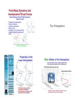
North American XB-70!
Nominal Configuration
Tips folded, 50% fuel, W = 38,524 lb
x
cm
@0.218 c
I
xx
= 1.8 ×10
6
slug-ft
2
I
yy
= 19.9 ×10
6
slug-ft
2
I
xx
= 22.1×10
6
slug-ft
2
I
xz
= −0.88 ×10
6
slug-ft
2
Rate of Change of
Angular Momentum
Newtons 2
nd
Law, Applied
to Rotational Motion"
• In inertial frame, rate of change of angular
momentum = applied moment (or torque), M"
dh
dt
=
d Iω
( )
dt
=
dI
dt
ω + I
d
ω
dt
=
Iω + I
ω = M =
m
x
m
y
m
z
"
#
$
$
$
$
%
&
'
'
'
'
• Angular
momentum and
rate vectors are
not necessarily
aligned"
h = Iω
Angular Momentum and Rate"
Rate of Change of
Angular Momentum
How Do We Get Rid of dI/dt in the
Angular Momentum Equation?"
• Dynamic equation in a body-referenced frame"
– Inertial properties of a constant-mass, rigid body are
unchanging in a body frame of reference"
– but a body-referenced frame is non-Newtonian
or non-inertial"
– Therefore, dynamic equation must be modified for
expression in a rotating frame"
d Iω
( )
dt
=
Iω + I
ω
• Chain Rule" and in an inertial frame"
I ≠ 0
Angular Momentum
Expressed in Two
Frames of Reference"
• Angular momentum and rate
are vectors"
– Expressed in either the inertial
or body frame"
– Two frames related algebraically
by the rotation matrix"
h
B
t
( )
= H
I
B
t
( )
h
I
t
( )
; h
I
t
( )
= H
B
I
t
( )
h
B
t
( )
ω
B
t
( )
= H
I
B
t
( )
ω
I
t
( )
; ω
I
t
( )
= H
B
I
t
( )
ω
B
t
( )
Vector Derivative Expressed
in a Rotating Frame"
• Chain Rule"
• Consequently, the 2
nd
term is"
h
I
= H
B
I
h
B
+
H
B
I
h
B
Effect of !
body-frame rotation!
Rate of change !
expressed in body frame!
• Alternatively"
h
I
= H
B
I
h
B
+ ω
I
× h
I
= H
B
I
h
B
+
ω
I
h
I
ω =
0 −
ω
z
ω
y
ω
z
0 −
ω
x
−
ω
y
ω
x
0
#
$
%
%
%
%
&
'
(
(
(
(
" where the cross-product-
equivalent matrix of angular rate is"
H
B
I
h
B
=
ω
I
h
I
=
ω
I
H
B
I
h
B
External Moment Causes
Change in Angular Rate"
h
B
= H
I
B
h
I
+
H
I
B
h
I
= H
I
B
h
I
− ω
B
× h
B
= H
I
B
h
I
−
ω
B
h
B
= H
I
B
M
I
−
ω
B
I
B
ω
B
= M
B
−
ω
B
I
B
ω
B
"Positive rotation of
Frame B w.r.t.
Frame A is a
negative rotation of
Frame A w.r.t.
Frame B"
M
I
=
m
x
m
y
m
z
!
"
#
#
#
#
$
%
&
&
&
&
I
; M
B
= H
I
B
M
I
=
m
x
m
y
m
z
!
"
#
#
#
#
$
%
&
&
&
&
B
=
L
M
N
!
"
#
#
#
$
%
&
&
&
• Moment = torque = force x moment arm"
• In the body frame of reference, the angular momentum change is"
Rate of Change of Body-Referenced
Angular Rate due to External
Moment"
• For constant body-axis inertia matrix"
h
B
= H
I
B
h
I
+
H
I
B
h
I
= H
I
B
h
I
− ω
B
× h
B
= H
I
B
h
I
−
ω
B
h
B
= H
I
B
M
I
−
ω
B
I
B
ω
B
= M
B
−
ω
B
I
B
ω
B
• In the body frame of reference, the angular momentum change is"
ω
B
= I
B
−1
M
B
−
ω
B
I
B
ω
B
( )
• Consequently, the differential equation for angular rate of change is"
h
B
= I
B
ω
B
= M
B
−
ω
B
I
B
ω
B
Next Time:
Aircraft Equations of
Motion – 2
Reading
Aircraft Dynamics,
Virtual Textbook, Parts 8,9
Supplemental
Material
Direction Cosine Matrix
(also called Rotation Matrix)"
H
I
B
=
cos
δ
11
cos
δ
21
cos
δ
31
cos
δ
12
cos
δ
22
cos
δ
32
cos
δ
13
cos
δ
23
cos
δ
33
"
#
$
$
$
%
&
'
'
'
• Cosines of angles
between each I axis
and each B axis"
• Projections of vector
components"
r
B
= H
I
B
r
I
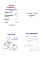
• Moments and products
of inertia tabulated for
geometric shapes with
uniform density"
Moments and
Products of
Inertia"
(Bedford & Fowler)"
• Construct aircraft
moments and products of
inertia from components
using parallel-axis
theorem"
• Model in Pro/ENGINEER,
etc."