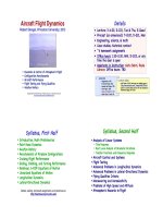
Aircraft Flight Dynamics Robert F. Stengel Lecture16 Aircraft Control Devices and Systems
Bạn đang xem bản rút gọn của tài liệu. Xem và tải ngay bản đầy đủ của tài liệu tại đây (1.77 MB, 19 trang )
Aircraft Control Devices
and Systems
Robert Stengel, Aircraft Flight Dynamics, MAE 331,
2012"
Copyright 2012 by Robert Stengel. All rights reserved. For educational use only.!
/>!
/>!
• Control surfaces"
• Control mechanisms"
• Flight control systems"
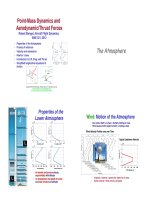
Design for Control"
• Elevator/stabilator: pitch control"
• Rudder: yaw control"
• Ailerons: roll control"
• Trailing-edge flaps: low-angle lift control"
• Leading-edge flaps/slats: High-angle
lift control"
• Spoilers: Roll, lift, and drag control"
• Thrust: speed/altitude control"
Critical Issues for Control"
• Effect of control surface deflections on aircraft motions"
– Generation of control forces and rigid-body moments on the aircraft"
– Rigid-body dynamics of the aircraft"
δ
E is an input for longitudinal motion"
θ
=
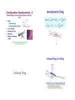
Mechanical, Power-Boosted System"
Grumman A-6!
McDonnell Douglas F-15!
Critical Issues for Control"
• Command and control of the control surfaces"
– Displacements, forces, and hinge moments of the
control mechanisms"
– Dynamics of control linkages included in model"
δ
E is a state for mechanical dynamics"
δ
E =
Control Surface Dynamics
and Aerodynamics
Aerodynamic and
Mechanical Moments
on Control Surfaces"
• Increasing size and speed of aircraft
leads to increased hinge moments"
• This leads to need for mechanical or
aerodynamic reduction of hinge
moments"
• Need for aerodynamically balanced
surfaces"
• Elevator hinge moment"
H
elevator
= C
H
elevator
1
2
ρ
V
2
Sc
Aerodynamic and Mechanical
Moments on Control Surfaces"
C
H
surface
= C
H
δ
δ
+ C
H
δ
δ
+ C
H
α
α
+ C
H
command
+
C
H
δ
: aerodynamic/mechanical damping moment
C
H
δ
: aerodynamic/mechanical spring moment
C
H
α
: floating tendency
C
H
command
: pilot or autopilot input
• Hinge-moment coefficient, C
H
"
– Linear model of dynamic effects"
Angle of Attack and
Control Surface Deflection"
• Horizontal tail at
positive angle of attack"
• Horizontal tail with
elevator control
surface"
• Horizontal tail with
positive elevator
deflection"
Floating and Restoring
Moments on a Control Surface"
• Positive elevator deflection produces a negative (restoring)
moment, H
δ
, on elevator due to aerodynamic or mechanical spring
"
• Positive angle of attack produces negative moment on the elevator"
• With stick free, i.e., no opposing torques, elevator floats up due
to negative H
δ
"
Dynamic Model of a Control
Surface Mechanism"
δ
− H
δ
δ
− H
δ
δ
= H
α
α
+ H
command
+
mechanism dynamics = external forcing
• Approximate control
dynamics by a 2
nd
-
order LTI system"
• Bring all torques and inertias to right side"
δ
E =
H
elevator
I
elevator
=
C
H
elevator
1
2
ρ
V
2
Sc
I
elevator
= C
H
δ
E
δ
E + C
H
δ
E
δ
E + C
H
α
α
+ C
H
command
+
$
%
&
'
1
2
ρ
V
2
Sc
I
elevator
≡ H
δ
E
δ
E + H
δ
E
δ
E + H
α
α
+ H
command
+
Dynamic Model of a Control
Surface Mechanism"
I
elevator
= effective inertia of surface, linkages, etc.
H
δ
E
=
∂
H
elevator
I
elevator
( )
∂
δ
; H
δ
E
=
∂
H
elevator
I
elevator
( )
∂δ
H
α
=
∂
H
elevator
I
elevator
( )
∂α
• Stability and control derivatives of
the control mechanism"
Coupling of System Model and Control
Mechanism Dynamics "
• 2
nd
-order model of control-deflection dynamics"
– Command input from cockpit"
– Forcing by aerodynamic effects"
• Control surface deflection"
• Aircraft angle of attack and angular rates"
• Short period approximation"
• Coupling with mechanism dynamics"
Δ
x
SP
= F
SP
Δx
SP
+ G
SP
Δu
SP
= F
SP
Δx
SP
+ F
δ
E
SP
Δx
δ
E
Δ
q
Δ
α
$
%
&
&
'
(
)
)
≈
M
q
M
α
1 −
L
α
V
N
$
%
&
&
&
'
(
)
)
)
Δq
Δ
α
$
%
&
&
'
(
)
)
+
M
δ
E
0
−
L
δ
E
V
N
0
$
%
&
&
&
'
(
)
)
)
Δ
δ
E
Δ
δ
E
$
%
&
'
(
)
Δ
x
δ
E
= F
δ
E
Δx
δ
E
+ G
δ
E
Δu
δ
E
+ F
SP
δ
E
Δx
SP
Δ
δ
E
Δ
δ
E
#
$
%
%
&
'
(
(
≈
0 1
H
δ
E
H
δ
E
#
$
%
%
&
'
(
(
Δ
δ
E
Δ
δ
E
#
$
%
&
'
(
+
0
−H
δ
E
#
$
%
%
&
'
(
(
Δ
δ
E
command
+
0 0
H
q
H
α
#
$
%
%
&
'
(
(
Δq
Δ
α
#
$
%
%
&
'
(
(
Short Period Model Augmented by
Control Mechanism Dynamics "
• Augmented dynamic equation"
• Augmented stability and control matrices"
F
SP/
δ
E
=
F
SP
F
δ
E
SP
F
SP
δ
E
F
δ
E
"
#
$
$
%
&
'
'
=
M
q
M
α
M
δ
E
0
1 −
L
α
V
N
−
L
δ
E
V
N
0
0 0 0 1
H
q
H
α
H
δ
E
H
δ
E
"
#
$
$
$
$
$
$
%
&
'
'
'
'
'
'
Δx
SP '
=
Δq
Δ
α
Δ
δ
E
Δ
δ
E
$
%
&
&
&
&
&
'
(
)
)
)
)
)
Δ
x
SP /
δ
E
= F
SP /
δ
E
Δx
SP /
δ
E
+ G
SP /
δ
E
Δ
δ
E
command
State Vector!
G
SP /
δ
E
=
0
0
0
H
δ
E
"
#
$
$
$
$
%
&
'
'
'
'
Roots of the Augmented Short
Period Model "
• Characteristic equation for short-period/elevator dynamics"
Δ
SP/
δ
E
s
( )
= sI
n
− F
SP/
δ
E
=
s − M
q
( )
−M
α
−M
δ
E
0
−1 s +
L
α
V
N
( )
L
δ
E
V
N
0
0 0 s −1
−H
q
−H
α
−H
δ
E
s − H
δ
E
( )
= 0
Δ
SP /
δ
E
s
( )
= s
2
+ 2
ζ
SP
ω
n
SP
s +
ω
n
SP
2
( )
s
2
+ 2
ζ
δ
E
ω
n
δ
E
s +
ω
n
δ
E
2
( )
Short Period" Control Mechanism"
Roots of the Augmented Short
Period Model "
• Coupling of the modes
depends on design
parameters"
M
δ
E
,
L
δ
E
V
N
, H
q
, and H
α
• Desirable for mechanical natural
frequency > short-period natural
frequency"
• Coupling dynamics can be
evaluated by root locus analysis"
Horn Balance"
C
H
≈ C
H
α
α
+ C
H
δ
E
δ
E + C
H
pilot input
• Stick-free case"
– Control surface free to float "
C
H
≈ C
H
α
α
+ C
H
δ
E
δ
E
• Normally "
C
H
α
< 0 : reduces short-period stability
C
H
δ
E
< 0 : required for mechanical stability
NACA TR-927, 1948!
Horn Balance"
• Inertial and aerodynamic
effects"
• Control surface in front of
hinge line"
– Increasing elevator
improves pitch stability, to a
point "
• Too much horn area"
– Degrades restoring moment "
– Increases possibility of
mechanical instability"
– Increases possibility of
destabilizing coupling to short-
period mode"
€
C
H
α
Overhang or
Leading-Edge
Balance"
• Area in front of the
hinge line"
• Effect is similar to
that of horn balance"
• Varying gap and
protrusion into
airstream with
deflection angle"
C
H
≈ C
H
α
α
+ C
H
δ
δ
+ C
H
pilot input
NACA TR-927, 1948!
All-Moving Control Surfaces"
• Particularly effective at supersonic speed (Boeing
Bomarc wing tips, North American X-15 horizontal
and vertical tails, Grumman F-14 horizontal tail)"
• SB.4s aero-isoclinic wing"
• Sometimes used for trim only (e.g., Lockheed L-1011
horizontal tail)"
• Hinge moment variations with flight condition"
Shorts SB.4!
Boeing !
Bomarc!
North American X-15!
Grumman F-14!
Lockheed L-1011!
Control Surface Types
Elevator"
• Horizontal tail and elevator
in wing wake at selected
angles of attack"
• Effectiveness of low
mounting is unaffected by
wing wake at high angle of
attack"
• Effectiveness of high-mounted
elevator is unaffected by wing
wake at low to moderate angle
of attack"
Ailerons"
• When one aileron goes up, the other goes down"
– Average hinge moment affects stick force"
Compensating Ailerons"
• Frise aileron"
– Asymmetric contour, with hinge line at or
below lower aerodynamic surface"
– Reduces hinge moment"
• Cross-coupling effects can be adverse or
favorable, e.g. yaw rate with roll"
– Up travel of one > down travel of other to
control yaw effect"
Abzug & Larrabee, 2002!
Spoilers"
• Spoiler reduces lift, increases drag"
– Speed control"
• Differential spoilers"
– Roll control "
– Avoid twist produced by outboard
ailerons on long, slender wings"
– free trailing edge for larger high-lift
flaps"
• Plug-slot spoiler on P-61 Black
Widow: low control force"
• Hinged flap has high hinge moment"
North American P-61!
Abzug & Larrabee, 2002!
Elevons"
• Combined pitch and roll control
using symmetric and
asymmetric surface deflection"
• Principally used on"
– Delta-wing configurations"
– Swing-wing aircraft"
Grumman F-14!
General Dynamics F-106!
Canards"
• Pitch control"
– Ahead of wing downwash"
– High angle of attack
effectiveness"
– Desirable flying qualities
effect (TBD)"
Dassault Rafale!
SAAB Gripen!
Yaw Control of Tailless Configurations"
• Typically unstable in pitch and yaw"
• Dependent on flight control system
for stability"
• Split ailerons or differential drag
flaps produce yawing moment"
McDonnell Douglas X-36!
Northrop Grumman B-2!
Rudder"
• Rudder provides yaw control"
– Turn coordination"
– Countering adverse yaw"
– Crosswind correction"
– Countering yaw due to engine loss"
• Strong rolling effect, particularly at high
α
"
• Only control surface whose nominal
aerodynamic angle is zero"
• Possible nonlinear effect at low deflection
angle"
• Insensitivity at high supersonic speed"
– Wedge shape, all-moving surface on North
American X-15"
Martin B-57!
Bell X-2!
Rudder Has Mechanical As Well as
Aerodynamic Effects "
! American Airlines 587 takeoff behind Japan Air 47, Nov. 12, 2001"
! Excessive periodic commands to rudder caused vertical tail failure"
Japan B-747!American A-300!
/>NTSB Simulation of American
Flight 587 "
! Flight simulation derived from digital flight data recorder (DFDR) tape"
Control Mechanization
Effects
Control Mechanization Effects"
• Fabric-covered control
surfaces (e.g., DC-3, Spitfire)
subject to distortion under air
loads, changing stability and
control characteristics"
• Control cable stretching"
• Elasticity of the airframe
changes cable/pushrod
geometry"
• Nonlinear control effects"
– friction"
– breakout forces"
– backlash"
Douglas DC-3!
Supermarine !
Spitfire!
Nonlinear Control Mechanism Effects"
• Friction"
• Deadzone"
Control Mechanization Effects"
• Breakout force"
• Force threshold"
B-52 Control Compromises to
Minimize Required Control Power
"
• Limited-authority rudder, allowed by "
– Low maneuvering requirement "
– Reduced engine-out requirement (1 of
8 engines) "
– Crosswind landing gear"
• Limited-authority elevator, allowed by "
– Low maneuvering requirement "
– Movable stabilator for trim"
– Fuel pumping to shift center of mass"
• Small manually controlled "feeler"
ailerons with spring tabs "
– Primary roll control from powered
spoilers, minimizing wing twist"
Internally Balanced
Control Surface"
! B-52 application"
! Control-surface fin
with flexible seal
moves within an
internal cavity in
the main surface"
! Differential
pressures reduce
control hinge
moment"
C
H
≈ C
H
α
α
+ C
H
δ
δ
+ C
H
pilot input
Boeing B-52!
B-52 Rudder Control Linkages"
B-52 Mechanical
Yaw Damper"
• Combined stable rudder tab, low-friction bearings, small
bobweight, and eddy-current damper for B-52"
• Advantages"
– Requires no power, sensors, actuators, or computers"
– May involve simple mechanical components"
• Problems"
– Misalignment, need for high precision"
– Friction and wear over time"
– Jamming, galling, and fouling"
– High sensitivity to operating conditions, design difficulty"
Boeing B-47 Yaw Damper"
• Yaw rate gyro drives rudder to increase
Dutch roll damping"
• Comment: The plane wouldnt need this
contraption if it had been designed right
in the first place."
• However, mode characteristics
especially damping vary greatly with
altitude, and most jet aircraft have yaw
dampers"
• Yaw rate washout to reduce opposition to
steady turns"
Northrop YB-49 Yaw Damper!
• Minimal directional stability due to small vertical surfaces
and short moment arm"
• Clamshell rudders, like drag flaps on the B-2 Spirit"
• The first stealth aircraft, though that was not intended"
• Edwards AFB named after test pilot, Glen Edwards,
Princeton MSE, killed testing the aircraft"
• B-49s were chopped up after decision not to go into
production"
• Northrop had the last word: it built the B-2!
Northrop YB-49!
Northrop/Grumman B-2!
Northrop N-9M!
Instabilities Due To
Control Mechanization
"
• Aileron buzz (aero-mechanical instability; P-80)"
• Rudder snaking (Dutch roll/mechanical coupling; Meteor, He-162)"
• Aeroelastic coupling (B-47, Boeing 707 yaw dampers)"
Rudder Snaking"
• Control-free dynamics"
– Nominally symmetric control position"
– Internal friction"
– Aerodynamic imbalance"
• Coupling of mechanical motion with
Dutch roll mode"
Douglas DC-2!
• Solutions"
– Trailing-edge bevel"
– Flat-sided surfaces"
– Fully powered controls
"
Roll/Spiral Limit Cycle
Due to Aileron Imbalance"
• Unstable nonlinear
oscillation grows
until it reaches a
steady state"
• This is called a
limit cycle
"
Lockheed P-38!
Control Surface Buzz"
North American FJ-4!
• At transonic speed, normal shocks
may occur on control surface"
– With deflection, shocks move
differentially "
– Possibility of self-sustained
nonlinear oscillation (limit cycle)"
ARC R&M 3364!
• Solutions "
– Splitter-plate rudder
fixes shock location
for small deflections"
– Blunt trailing edge"
– Fully powered
controls with
actuators at the
surfaces"
Rudder Lock"
• Rudder deflected to stops at high
sideslip; aircraft trims at high
α
"
• 3 necessary ingredients"
– Low directional stability at high
sideslip due to stalling of fin"
– High (positive) hinge moment-
due-to-sideslip at high sideslip
(e.g., B-26)!
– Negative rudder yawing moment "
• Problematical if rudder is
unpowered and requires high
foot-pedal force (rudder float of
large WWII aircraft)"
• Solutions"
– Increase high-sideslip directional
stability by adding a dorsal fin
(e.g., B-737-100 (before),
B-737-400 (after))"
– Hydraulically powered rudder"
Martin B-26!
Boeing 737-100!
Boeing 737-400!
Control Systems
SAS = Stability Augmentation System!
Downsprings and Bobweights"
• Adjustment of "
– Stick-free pitch trim moment"
– Stick-force sensitivity to
airspeed*"
• Downspring"
– Mechanical spring with low spring
constant"
– Exerts a ~constant trailing-edge
down moment on the elevator!
• Bobweight"
– Similar effect to that of the
downspring"
– Weight on control column that
affects feel or basic stability"
– Mechanical stability augmentation
(weight is sensitive to aircraft’s
angular rotation)"
Beechcraft B-18!
* See pp. 541-545, Section 5.5, Flight Dynamics!
Effect of Scalar Feedback Control
on Roots of the System "
Δy(s) = H (s)Δu(s) =
kn(s)
d(s)
Δu(s) =
kn(s)
d(s)
KΔ
ε
(s)
• Block diagram algebra"
H (s) =
kn(s)
d(s)
= KH (s) Δy
c
(s) − Δy(s)
[ ]
Δy(s) = KH(s)Δy
c
(s) − KH (s)Δy(s)
K
Closed-Loop Transfer Function "
1+ KH (s)
[ ]
Δy(s) = KH (s)Δy
c
(s)
Δy(s)
Δy
c
(s)
=
KH (s)
1+ KH (s)
[ ]
Roots of the Closed-Loop System "
• Closed-loop roots are solutions to"
Δ
closed
loop
(s) = d(s) + Kkn(s) = 0
or!
K
kn(s)
d(s)
= −1
Δy(s)
Δy
c
(s)
=
K
kn(s)
d(s)
1+ K
kn(s)
d(s)
"
#
$
%
&
'
=
Kkn(s)
d(s)+ Kkn(s)
[ ]
=
Kkn(s)
Δ
closed
loop
s
( )
Root Locus Analysis of Pitch Rate Feedback to
Elevator (2
nd
-Order Approximation)"
KH s
( )
= K
Δq(s)
Δ
δ
E(s)
= K
k
q
s − z
q
( )
s
2
+ 2
ζ
SP
ω
n
SP
s +
ω
n
SP
2
= −1
! # of roots = 2"
! # of zeros = 1!
! Destinations of roots (for k =
±∞):"
! 1 root goes to zero of n(s)"
! 1 root goes to infinite radius"
! Angles of asymptotes,
θ
, for
the roots going to ∞"
! K -> +∞: –180 deg"
! K -> –∞: 0 deg"
Root Locus Analysis of Pitch
Rate Feedback to Elevator
(2
nd
-Order Approximation)"
• Center of gravity : doesnt
matter"
• Locus on real axis"
– K > 0: Segment to the left of
the zero"
– K < 0: Segment to the right of
the zero"
Feedback effect is analogous
to changing M
q
"
Root Locus Analysis of Angular
Feedback to Elevator (4
th
-Order Model)*"
Flight Path Angle! Pitch Rate!
Pitch Angle! Angle of Attack!
* p. 524, Flight Dynamics"
Root Locus Analysis of Angular
Feedback to Thrust (4
th
-Order Model)"
Flight Path Angle!
Pitch Rate!
Pitch Angle! Angle of Attack!
Direct Lift and
Propulsion Control
Direct-Lift Control-Approach
Power Compensation"
• F-8 Crusader "
– Variable-incidence wing,
better pilot visibility"
– Flight path control at low
approach speeds "
• requires throttle use "
• could not be accomplished
with pitch control alone
"
– Engine response time is slow"
– Flight test of direct lift control
(DLC), using ailerons as flaps"
• Approach power
compensation for A-7 Corsair
II and direct lift control studied
using Princeton’s Variable-
Response Research Aircraft"
Princeton VRA!
Vought A-7!
Vought F-8!
Direct-Lift/Drag Control"
• Direct-lift control on S-3A
Viking"
– Implemented with spoilers"
– Rigged up during landing
to allow ± lift."
• Speed brakes on T-45A
Goshawk make up for slow
spool-up time of jet engine"
– BAE Hawk's speed brake
moved to sides for carrier
landing"
– Idle speed increased from
55% to 78% to allow more
effective modulation via
speed brakes"
Lockheed S-3A!
Boeing T-45!
Next Time:
Flight Testing for
Stability and Control
Reading
Flight Dynamics, 419-428
Aircraft Stability and Control, Ch. 3
Virtual Textbook, Part 17
Supplementary!
Material!
Trailing-Edge
Bevel Balance"
• Bevel has strong
effect on
aerodynamic hinge
moments"
• See discussion in
Abzug and Larrabee!
C
H
≈ C
H
α
α
+ C
H
δ
δ
+ C
H
pilot input
Control Tabs"
• Balancing or geared tabs"
– Tab is linked to the main surface
in opposition to control motion,
reducing the hinge moment with
little change in control effect"
• Flying tabs"
– Pilot's controls affect only the
tab, whose hinge moment
moves the control surface"
• Linked tabs"
– divide pilot's input between tab
and main surface"
• Spring tabs "
– put a spring in the link to the
main surface"
Control Flap Carryover Effect on
Lift Produced By Total Surface"
from Schlichting & Truckenbrodt!
C
L
δ
E
C
L
α
vs.
c
f
x
f
+ c
f
€
c
f
x
f
+ c
f
( )
Aft Flap vs. All-Moving
Control Surface"
• Carryover effect"
– Aft-flap deflection can be almost as effective as
full surface deflection at subsonic speeds"
– Negligible at supersonic speed"
• Aft flap "
– Mass and inertia lower, reducing likelihood of
mechanical instability"
– Aerodynamic hinge moment is lower"
– Can be mounted on structurally rigid main
surface"
Mechanical and Augmented
Control Systems
"
• Mechanical system"
– Push rods, bellcranks, cables, pulleys"
• Power boost"
– Pilot's input augmented by hydraulic servo that
lowers manual force"
• Fully powered (irreversible) system"
– No direct mechanical path from pilot to
controls"
– Mechanical linkages from cockpit controls to
servo actuators"
"
Boeing 767 Elevator Control System"
Abzug & Larrabee, 2002!
Boeing 777 Fly-By-Wire Control System"
Classical Lateral Control Logic for
a Fighter Aircraft
(c.1970)"
MIL-DTL-9490E, Flight Control Systems - Design, Installation and Test of
Piloted Aircraft, General Specification for, 22 April 2008"
Superseded for new designs on same date
by"
SAE-AS94900"
/>The Unpowered F4D Rudder"
• Rudder not a problem under normal flight conditions"
– Single-engine, delta-wing aircraft requiring small rudder inputs"
• Not a factor for upright spin "
– Rudder was ineffectual, shielded from flow by the large delta wing"
• However, in an inverted spin "
– rudder effectiveness was high "
– floating tendency deflected rudder in a pro-spin direction "
– 300 lb of pedal force to neutralize the rudder"
• Fortunately, the test aircraft had a spin chute"
Powered Flight Control Systems"
• Early powered systems had a single
powered channel, with mechanical
backup"
– Pilot-initiated reversion to
"conventional" manual controls"
– Flying qualities with manual control
often unacceptable"
• Reversion typically could not be
undone"
– Gearing change between control stick
and control to produce acceptable pilot
load"
– Flying qualities changed during a high-
stress event"
• Hydraulic system failure was common"
– Redundancy was needed"
• Alternative to eject in military aircraft"
A4D!
A3D!
B-47!
Advanced Control Systems"
• Artificial-feel system"
– Restores control forces to those of an
"honest" airplane"
– "q-feel" modifies force gradient"
– Variation with trim stabilizer angle"
– Bobweight responds to gravity and to
normal acceleration"
• Fly-by-wire/light system"
– Minimal mechanical runs"
– Command input and feedback signals
drive servo actuators"
– Fully powered systems"
– Move from hydraulic to electric power"
Control-Configured Vehicles"
• Command/stability augmentation"
• Lateral-directional response"
– Bank without turn"
– Turn without bank"
– Yaw without lateral translation"
– Lateral translation without yaw"
– Velocity-axis roll (i.e., bank)"
• Longitudinal response"
– Pitch without heave"
– Heave without pitch"
– Normal load factor"
– Pitch-command/attitude-hold"
– Flight path angle"
USAF F-15 IFCS!
Princeton Variable-Response Research Aircraft!
USAF AFTI/F-16!
United Flight 232, DC-10
Sioux City, IA, 1989"
• Uncontained engine failure damaged all three flight control
hydraulic systems (
/>United Flight 232, DC-10
Sioux City, IA, 1989"
• Pilot maneuvered on differential control of engines to make a runway approach"
• 101 people died"
• 185 survived"
Propulsion Controlled Aircraft"
• Proposed backup attitude control in event of flight control system failure"
• Differential throttling of engines to produce control moments"
• Requires feedback control for satisfactory flying qualities"
NASA MD-11 PCA Flight Test!
NASA F-15 PCA Flight Test!
Proposed retrofit to McDonnell-Douglas
(Boeing) C-17
!