Aircraft Flight Dynamics Robert F. Stengel Lecture20 Flying Qualities Criteria
Bạn đang xem bản rút gọn của tài liệu. Xem và tải ngay bản đầy đủ của tài liệu tại đây (1.5 MB, 12 trang )
Flying Qualities Criteria
Robert Stengel, Aircraft Flight Dynamics
MAE 331, 2012
"
Copyright 2012 by Robert Stengel. All rights reserved. For educational use only.!
/>!
/>!
• MIL-F-8785C criteria!
• CAP, C*, and other longitudinal
criteria"
•
ϕ/β, ω
ϕ
/ω
, and other lateral-
directional criteria"
• Pilot-vehicle interactions"
• Flight control system design"
Design for Satisfactory Flying Qualities"
• Satisfy procurement requirement (e.g., Mil
Standard)"
• Satisfy test pilots (e.g., Cooper-Harper ratings)"
• Avoid pilot-induced oscillations (PIO)"
• Minimize time-delay effects"
• Time- and frequency-domain criteria"
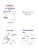
MIL-F-8785C Identifies Satisfactory, Acceptable,
and Unacceptable Response Characteristics"
Damping Ratio"
Step Response"
Frequency Response"
Short-period angle-of-attack
response to elevator input!
Longitudinal Criteria
Long-Period Flying Qualities Criteria
(MIL-F-8785C)!
• Static speed stability"
– No tendency for aperiodic divergence"
• Phugoid oscillation -> 2 real roots, 1 that is unstable"
– Stable control stick position and force gradients"
• e.g., Increasing pull position and force with decreasing speed"
A. Non-terminal flight requiring rapid
maneuvering"
B. Non-terminal flight requiring gradual
maneuvering"
C. Terminal flight"
1. Clearly adequate for the mission"
2. Adequate to accomplish the mission, with
some increase in workload"
3. Aircraft can be controlled safely, but
workload is excessive"
Level of Performance!
Flight Phase!
Long-Period Flying Qualities Criteria
(MIL-F-8785C)!
• Flight path stability [Phase C]"
1. (Δγ/ΔV)
SS
< 0.06 deg/kt"
2. (Δγ/ΔV)
SS
< 0.15 deg/kt"
3. (Δγ/ΔV)
SS
< 0.24 deg/kt"
ΔV
SS
= aΔ
δ
E
SS
+ 0
( )
Δ
δ
T
SS
+ bΔ
δ
F
SS
Δ
γ
SS
= cΔ
δ
E
SS
+ dΔ
δ
T
SS
+ eΔ
δ
F
SS
• Lecture 19"
Δ
γ
SS
ΔV
SS
=
c
a
(with appropriate scaling)
• From 4
th
-order model"
Long-Period Flying Qualities Criteria
(MIL-F-8785C)!
• Phugoid stability"
1. Damping ratio ≥ 0.04"
2. Damping ratio ≥ 0"
3. Time to double, T
2
≥ 55 sec"
€
T
2
Ph
= −0.693/
ζ
Ph
ω
n
Ph
Time to Double!
Short Period Criteria"
• Important parameters"
– Short-period natural frequency"
– Damping ratio"
– Lift slope"
– Step response"
• Over-/under-shoot"
• Rise time"
• Settling time"
• Pure time delay"
– Pitch angle response"
– Normal load factor response"
– Flight path angle response (landing)"
Space Shuttle Pitch-Response Criterion"
Short-Period Approximation
Transfer Functions"
• Elevator to pitch rate"
Δq(s)
Δ
δ
E(s)
=
k
q
s − z
q
( )
s
2
+ 2
ζ
SP
ω
n
SP
s +
ω
n
SP
2
≡
k
q
s +
1
T
θ
2
(
)
*
+
,
-
s
2
+ 2
ζ
SP
ω
n
SP
s +
ω
n
SP
2
• Pure gain or phase change in feedback
control cannot produce instability"
Bode Plot!
Nichols Chart!
Root Locus!
Short-Period Approximation
Transfer Functions"
• Elevator to pitch angle"
• Integral of prior example"
Δ
θ
(s)
Δ
δ
E(s)
=
k
q
s − z
q
( )
s s
2
+ 2
ζ
SP
ω
n
SP
s +
ω
n
SP
2
( )
• Pure gain or phase change in feedback
control cannot produce instability"
Bode Plot!
Nichols Chart!
Root Locus!
Normal Load Factor"
• Therefore, with negligible L
δ
E
(aft tail/canard effect)"
Δn
z
=
V
N
g
Δ
α
− Δq
( )
= −
V
N
g
L
α
V
N
Δ
α
+
L
δ
E
V
N
Δ
δ
E
%
&
'
(
)
*
∂
Δn
z
(s)
∂
Δ
δ
E(s)
=
1
g
L
α
∂
Δ
α
(s)
∂
Δ
δ
E(s)
+ L
δ
E
%
&
'
(
)
*
≈
L
α
g
%
&
'
(
)
*
∂
Δ
α
(s)
∂
Δ
δ
E(s)
positive down!
positive up!
Δ
α
(s)
Δ
δ
E(s)
≈
k
α
s
2
+ 2
ζ
SP
ω
n
SP
s +
ω
n
SP
2
• Elevator to angle of attack (L
δ
E
= 0)"
/>Control
Anticipation
Parameter, CAP"
• Inner ear senses angular acceleration about 3 axes"
€
Δ
˙
q (0) = M
δ
E
−
M
α
V
N
+ L
α
L
δ
E
&
'
(
)
*
+
Δ
δ
E
SS
Δn
SS
=
V
N
g
Δq
SS
= −
V
N
g
&
'
(
)
*
+
M
δ
E
L
α
V
N
− M
α
L
δ
E
V
N
&
'
(
)
*
+
M
q
L
α
V
N
+ M
α
&
'
(
)
*
+
Δ
δ
E
SS
CAP =
Δ
q(0)
Δn
SS
=
− M
δ
E
−
M
α
V
N
+ L
α
L
δ
E
%
&
'
(
)
*
M
q
L
α
V
N
+ M
α
( )
L
α
M
δ
E
− L
δ
E
M
α
( )
g
• Inner ear cue should aid pilot in anticipating
commanded normal acceleration"
Initial Angular
Acceleration!
Desired
Normal Load
Factor!
Control
Anticipation
Factor!
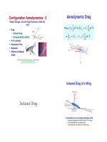
MIL-F-8785C
Short-Period
Flying
Qualities
Criterion"
CAP =
− M
q
L
α
V
N
+ M
α
( )
L
α
g
≈
ω
n
SP
2
n
z
/
α
€
ω
n
SP
vs.
n
z
α
1. Clearly adequate for the mission"
2. Adequate to accomplish the
mission, with some increase in
workload"
3. Aircraft can be controlled safely,
but workload is excessive"
Level of
Performance!
with L
δ
E
= 0!
• CAP = constant
along Level
Boundaries"
CAP!
Control Anticipation Parameter vs.
Short-Period Damping Ratio "
(MIL-F-8785C, Category A)"
CAP =
− M
q
L
α
V
N
+ M
α
( )
L
α
g
≈
ω
n
SP
2
n
z
/
α
C* Criterion"
! Below V
crossover
, Δq is pilots primary control objective"
! Above V
crossover
, Δn
pilot
is the primary control objective"
C* = Δn
pilot
+
V
crossover
g
Δq
= l
pilot
Δ
q +Δn
cm
( )
+
V
crossover
g
Δq
= l
pilot
Δ
q +
V
N
g
Δq −Δ
α
( )
$
%
&
'
(
)
+
V
crossover
g
Δq
Fighter Aircraft: V
crossover
≈ 125 m / s
• Hypothesis"
– C* blends normal load factor at pilots location and pitch rate"
– Step response of C* should lie within acceptable envelope"
Gibson Dropback Criterion
for Pitch Angle Control
"
• Step response of pitch rate
should have overshoot for
satisfactory pitch and flight
path angle response
!
Δq(s)
Δ
δ
E(s )
=
k
q
s +
1
T
θ
2
$
%
&
&
'
(
)
)
s
2
+ 2
ζ
SP
ω
n
SP
s +
ω
n
SP
2
=
k
q
s +
ω
n
SP
ζ
SP
$
%
&
'
(
)
s
2
+ 2
ζ
SP
ω
n
SP
s +
ω
n
SP
2
z
q
−
1
T
θ
2
= −
ω
n
SP
ζ
SP
%
&
'
(
)
*
• Criterion is satisfied when!
Gibson, 1997!
Lateral-Directional Criteria
Lateral-Directional
Flying Qualities
Parameters"
• Lateral Control Divergence Parameter,
LCDP!
•
ϕ/β
Effect"
•
ω
ϕ
/ω
Effect!
Lateral Control Divergence
Parameter (LCDP)"
• Aileron deflection produces yawing as well as rolling moment"
– Favorable yaw aids the turn command"
– Adverse yaw opposes it"
• Equilibrium response to constant aileron input "
Δ
φ
S
Δ
δ
A
S
=
N
β
+ N
r
Y
β
V
N
%
&
'
(
)
*
L
δ
A
− L
β
+ L
r
Y
β
V
N
%
&
'
(
)
*
N
δ
A
g
V
N
L
β
N
r
− L
r
N
β
( )
• Large-enough N
δ
A
effect can reverse the sign of the response"
– Can occur at high angle of attack "
– Can cause departure from controlled flight"
• Lateral Control Divergence Parameter provides simplified criterion"
LCDP ≡ C
n
β
−
C
n
δ
A
C
l
δ
A
C
l
β
N
β
( )
L
δ
A
− L
β
( )
N
δ
A
L
δ
A
= N
β
−
N
δ
A
L
δ
A
L
β
ω
Φ
/
ω
d
Effect!
• Aileron-to-roll-angle transfer function "
Δ
φ
(s)
Δ
δ
A(s)
=
k
φ
s
2
+ 2
ζ
φ
ω
φ
s +
ω
φ
2
( )
s −
λ
S
( )
s −
λ
R
( )
s
2
+ 2
ζ
DR
ω
n
DR
s +
ω
n
DR
2
( )
ω
ϕ
is the natural frequency of the complex zeros"
ω
d
=
ω
nDR
is the natural frequency of the Dutch roll mode"
• Conditional instability may occur with closed-
loop control of roll angle, even with a perfect pilot"
ω
ϕ
/ω
Effect"
• As feedback gain increases, Dutch roll roots go to numerator zeros "
• If zeros are over poles, conditional instability results"
Δ
φ
(s)
Δ
δ
A(s)
=
k
φ
s
2
+ 2
ζ
φ
ω
φ
s +
ω
φ
2
( )
s −
λ
S
( )
s −
λ
R
( )
s
2
+ 2
ζ
DR
ω
n
DR
s +
ω
n
DR
2
( )
ϕ/β
Effect"
•
ϕ/β
measures the degree of rolling response in the
Dutch roll mode"
– Large
ϕ/β
: Dutch roll is primarily a rolling motion"
– Small
ϕ/β
: Dutch roll is primarily a yawing motion"
• Eigenvectors, e
i
, indicate the degree of participation
of the state component in the i
th
mode of motion"
det sI − F
( )
= s −
λ
1
( )
s −
λ
2
( )
s −
λ
n
( )
λ
i
I − F
( )
e
i
= 0
Eigenvectors!
• Eigenvectors, e
i
, are solutions to the equation"
λ
i
I − F
( )
e
i
= 0, i = 1, n
or
λ
i
e
i
= Fe
i
, i = 1, n
• For each eigenvalue, the corresponding eigenvector
can be found (within an arbitrary constant) from"
Adj
λ
i
I − F
( )
= a
1
e
i
a
2
e
i
… a
n
e
i
( )
, i = 1, n
MATLAB
V,D
( )
= eig F
( )
V: Modal Matrix (i.e., Matrix of Eigenvectors)
D: Diagonal Matrix of Corresponding Eigenvalues
ϕ/β
Effect"
• With
λ
i
chosen as a complex root of the Dutch roll mode,
the corresponding eigenvector is"
e
DR+
=
e
r
e
β
e
p
e
φ
#
$
%
%
%
%
%
&
'
(
(
(
(
(
DR+
=
σ
+ j
ω
( )
r
σ
+ j
ω
( )
β
σ
+ j
ω
( )
p
σ
+ j
ω
( )
φ
#
$
%
%
%
%
%
%
&
'
(
(
(
(
(
(
DR+
=
AR e
j
φ
( )
r
AR e
j
φ
( )
β
AR e
j
φ
( )
p
AR e
j
φ
( )
φ
#
$
%
%
%
%
%
%
%
&
'
(
(
(
(
(
(
(
DR+
•
ϕ/β
is the magnitude of the ratio of the
ϕ
and
β
eigenvectors"
φ
β
=
AR
( )
φ
AR
( )
β
=
V
N
g
#
$
%
&
'
(
ζ
DR
ω
n
DR
+
Y
β
V
N
+
L
β
L
r
#
$
%
&
'
(
2
+
ω
n
DR
1−
ζ
DR
2
( )
,
-
.
.
/
0
1
1
1
2
ϕ/β
Effect for the Business
Jet Example!
e
DR+
=
e
r
e
β
e
p
e
φ
#
$
%
%
%
%
%
%
%
&
'
(
(
(
(
(
(
(
DR+
=
0.525
0.416
0.603
0.433
#
$
%
%
%
%
&
'
(
(
(
(
DR+
φ
β
= 1.04
Roll/Sideslip Angle ratio in the Dutch roll mode!
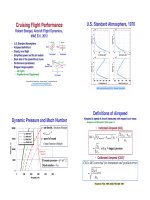
Early Lateral-Directional
Flying Qualities Criteria
!
T
1
2
= 0.693 /
ζ ω
n
v = V
N
β
O
Hara, via Etkin!
Ashkenas, via Etkin!
Time to Half!
Criteria for Lateral-Directional
Modes
(MIL-F-8785C)"
Maximum Roll-
Mode Time
Constant"
Minimum
Spiral-Mode
Time to Double"
Minimum Dutch Roll Natural
Frequency and Damping
(MIL-F-8785C)"
Pilot-Vehicle Interactions
Pilot-Induced Roll Oscillation"
Δ
φ
(s)
Δ
δ
A(s)
pilot in loop
=
K
p
/ T
p
s + 1 / T
p
$
%
&
'
(
)
k
φ
s
2
+ 2
ζ
φ
ω
φ
s +
ω
φ
2
( )
s −
λ
S
( )
s −
λ
R
( )
s
2
+ 2
ζ
DR
ω
n
DR
s +
ω
n
DR
2
( )
.
/
0
0
1
2
3
3
Aileron-to-Roll Angle
Root Locus
!
Pilot-Aircraft Nichols Chart
!
Pilot Transfer Function
!
Aircraft Transfer Function
!
YF-16!
YF-17 Landing
Approach Simulation
"
• Original design"
– Low short-period natural
frequency"
– Overdamped short period"
– Rapid roll-off of phase angle"
– PIO tendency, CHR = 10"
Elevator-to-pitch angle Nichols
chart (gain vs. phase angle)"
80°
Phase
Margin!
Gibson, 1997!
• Revised DFCS design"
– Higher short-period natural
frequency"
– Lower short-period damping"
– Reduced time delay in DFCS"
– CHR = 2"
Input frequency,
rad/s"
13 dB
Gain
Margin!
• Alternative pilot transfer function:
gain plus pure time delay
"
H j
ω
( )
pilot
= K
P
e
− j
ωτ
• Gain = constant"
• Phase angle linear in frequency"
• As input frequency increases,
ϕ(ω)
eventually > –180°
!
But Stability Margins Were Large
… How Could CHR = 10?
"
K
P
e
− j
ωτ
= K
P
K
P
e
− j
ωτ
( )
= − j
ωτ
H s
( )
pilot
=
Δu s
( )
Δ
ε
s
( )
= K
P
e
−
τ
s
Inverse
Problem of
Lateral Control!
• Given a flight path, what
is the control history that
generates it? "
– Necessary piloting
actions "
– Control-law design"
• Aileron-rudder
interconnect (ARI)
simplifies pilot input"
Grumman F-14 Tomcat!
Yaw Angle" Roll Angle"
Lateral-Stick
Command"
Angle of attack (
α
) =
10 deg; ARI off"
α
= 30 deg; ARI off"
α
= 30 deg; ARI on"
Stengel, Broussard, 1978!
Flight Control System
Design
Control System
Design Methods!
• Linear-quadratic (LQ) regulator"
• Pole placement"
• Parametric optimization"
• Nonlinear inverse dynamics"
• Neural networks"
• Noisy, incomplete measurements"
– State observer"
– Kalman filter (optimal estimator)"
• Assume Gaussian errors"
• Combine with LQ regulator"
• LQG regulator"
• Control at all points in flight envelope"
– Robustness"
– Gain scheduling"
– Adaptive control"
Proportional Stability Augmentation
with Command Input!
Δu t
( )
= C
F
Δy
C
t
( )
− C
B
Δx t
( )
Section 4.7, Flight Dynamics"
dim Δu t
( )
"
#
$
%
= m × 1; dim Δx t
( )
"
#
$
%
= n ×1
dim Δy
C
t
( )
"
#
$
%
= r × 1, r ≤ m
dim C
F
[ ]
= m × r; dim C
B
[ ]
= m × n
• Full state feedback"
• Command = desired output"
– r (≤ m) components"
– Cannot have more independent command inputs,
Δy
C
(t), than independent control inputs, Δu(t)"
Proportional Stability Augmentation
with Command Input!
Δ
x t
( )
= FΔx t
( )
+ GΔu t
( )
Δy t
( )
= H
x
Δx t
( )
; H
u
0
Δu t
( )
= C
F
Δy
C
t
( )
− C
B
Δx t
( )
Δ
x t
( )
= FΔx t
( )
+ G C
F
Δy
C
t
( )
− C
B
Δx t
( )
#
$
%
&
= F − GC
B
Δx t
( )
#
$
%
&
Δx t
( )
+ GC
F
Δy
C
t
( )
= F
CL
Δx t
( )
+ G
CL
Δy
C
t
( )
• Satisfy flying qualities criteria by adjusting
gains of the closed-loop command/stability
augmentation system"
Section 4.7, Flight Dynamics"
Dynamics and Control!
Substitute Control in Dynamic Equation!
• Eigenvalues"
• Root loci"
• Transfer functions"
• Bode plots"
• Nichols charts"
• "
Next Time:
Maneuvering and Aeroelasticity
Reading
Flight Dynamics, 681-785
Virtual Textbook, Part 21
Supplemental
Material
Large Aircraft Flying Qualities"
• High wing loading, W/S"
• Distance from pilot to rotational center"
• Slosh susceptibility of large tanks"
• High wing span -> short relative tail length"
– Higher trim drag"
– Increased yaw due to roll, need for rudder
coordination"
– Reduced rudder effect"
• Altitude response during approach"
– Increased non-minimum-phase delay in
response to elevator"
– Potential improvement from canard"
• Longitudinal dynamics"
– Phugoid/short-period resonance"
• Rolling response (e.g., time to bank)"
• Reduced static stability"
• Off-axis passenger comfort in BWB turns"
Criteria for Oscillations and Excursions
(MIL-F-8785C)"
Criteria for Oscillations and Excursions
(MIL-F-8785C)!
Proportional-Integral Command and
Stability Augmentation!
Δu t
( )
= C
F
Δy
C
t
( )
− C
I
Δy t
( )
− Δy
C
t
( )
#
$
%
&
dt
∫
− C
B
Δx t
( )
Section 4.7, Flight Dynamics"
• Full state feedback"
• Command = desired output"
– r (≤ m) components"
• Integral compensation eliminates long-term (bias) errors"
Proportional-Integral Command and
Stability Augmentation!
Δ
x t
( )
= FΔx t
( )
+ GΔu t
( )
Δy t
( )
= H
x
Δx t
( )
; H
u
0
Δu t
( )
= C
F
Δy
C
t
( )
− C
I
Δy t
( )
− Δy
C
t
( )
#
$
%
&
dt
∫
− C
B
Δx t
( )
Δ
x t
( )
= FΔx t
( )
+ G C
F
Δy
C
t
( )
+ C
I
Δy t
( )
− Δy
C
t
( )
#
$
%
&
dt
∫
− C
B
Δx t
( )
{ }
= F − GC
B
[ ]
Δx t
( )
+ G C
F
Δy
C
t
( )
+ C
I
Δy
C
t
( )
− H
x
Δx t
( )
#
$
%
&
dt
∫
{ }
Section 4.7, Flight Dynamics"
Dynamics and Control!
Substitute Control in Dynamic Equation!
Proportional-Integral
Command and Stability
Augmentation!
Δy t
( )
= H
x
Δx t
( )
; H
u
0
Δξ t
( )
Δy
C
t
( )
− Δy t
( )
$
%
&
'
dt
∫
= Δy
C
t
( )
− H
x
Δx t
( )
$
%
&
'
dt
∫
Δ
ξ t
( )
Δy
C
t
( )
− H
x
Δx t
( )
Δ
x t
( )
= F
CL
Δx t
( )
+ GC
F
Δy
C
t
( )
+ GC
I
Δξ t
( )
Δ
x t
( )
Δ
ξ t
( )
#
$
%
%
&
'
(
(
=
F
CL
GC
I
−H
x
0
#
$
%
%
&
'
(
(
Δx t
( )
Δξ t
( )
#
$
%
%
&
'
(
(
+
G
CL
I
#
$
%
%
&
'
(
(
Δy
C
t
( )
Section 4.7, Flight Dynamics"
• Define integral state, Δξ(t)"
• dim[Δξ(t)] = dim[Δy(t)]"
• Augmented dynamic equation"
Proportional-Integral
Command and Stability
Augmentation!
• Satisfy flying qualities criteria by adjusting gains of the
closed-loop command/stability augmentation system"
• New modes of motion in augmented system"
• Eigenvalues"
• Root loci"
• Transfer functions"
• Bode plots"
• Nichols charts"
• "
Δχ t
( )
Δx t
( )
Δξ t
( )
$
%
&
&
'
(
)
)
; dim Δχ t
( )
$
%
'
(
= n + r
( )
× 1
Δ
χ t
( )
= F
CL
' Δχ t
( )
+ G
CL
' Δy
C
t
( )
• Define augmented
state vector"
• Standard form
dynamic equation"
Proportional-Filter Stability
Augmentation with Command Input!
Δu t
( )
= + C
F
Δy
C
t
( )
− C
B
Δx t
( )
− −C
I
Δu t
( )
#
$
%
&
dt
∫
Section 4.7, Flight Dynamics"
Flight Testing Videos!
/>http://
www.youtube.com/watch?v=t6DdlPoPOE4!
/>!