Internetworking with TCP/IP- P31 docx
Bạn đang xem bản rút gọn của tài liệu. Xem và tải ngay bản đầy đủ của tài liệu tại đây (530.55 KB, 10 trang )
Sec.
14.5
Core
Routers
259
To avoid the inefficiencies default routes cause, Internet designers arranged for
all
core routers to exchange routing information so that each would have complete informa-
tion about optimal routes to all possible destinations. Because each core router knew
routes to all possible destinations, it did not need a default route.
If
the destination ad-
dress on a datagram was not in a core router's routing table, the router would generate
an ICMP destination unreachable message and drop the datagram. In essence, the core
design avoided inefficiency by eliminating default routes.
Figure
14.3
depicts the conceptual basis of a core routing architecture. The figure
shows a central core system consisting of one or more core routers, and a set of outly-
ing routers at local sites. Outlying routers keep information about local destinations and
use a'default route that sends datagrams destined for other sites to the core.
Figure
143
The routing architecture of a simplistic core system showing de-
fault routes. Core routers do not use default routes; outlying
routers, labeled
Li,
each have a default route that points to the
core.
Although the simplistic core architecture illustrated in Figure
14.3
is easy to under-
stand, it became impractical for three reasons. First, the Internet outgrew a single, cen-
trally managed long-haul backbone. The topology became complex and the protocols
needed to maintain consistency among core routers became nontrivial. Second, not
every site could have a core router connected to the backbone, so additional routing
structure and protocols were needed. Third, because core routers
all
interacted to ensure
consistent routing infornlation, the core architecture did not scale to arbitrary size. We
will return to this last problem in Chapter
15
after we examine the protocols that the
core system used to exchange routing infonation.
260
Routing: Cores,
Peers,
And Algorithms Chap.
14
14.6
Beyond The Core Architecture To Peer Backbones
The introduction of the NSFNET backbone into the Internet added new complexity
to the routing structure. From the core system point of view, the co~ection to
NSFNET was initially no different than the
co~ection to any other site. NSFNET at-
tached to the ARPANET backbone through a single router in Pittsburgh. The core had
explicit routes to all destinations in NSFNET. Routers inside NSFNET knew about lo-
cal destinations and used a default route to send all non-NSFNET traffic to the core via
the Pittsburgh router.
As NSFNET grew to become a major part of the Internet, it became apparent that
the core routing architecture would not suffice. The most important conceptual change
occurred when multiple connections were added between the ARPANET and NSFNET
backbones. We say that the two became
peer backbone networks
or simply
peers.
Fig-
ure
14.4
illustrates the resulting peer topology.
HOST
1
ARPANET BACKBONE HOST
2
HOST
3
NSFNET BACKBONE HOST
4
Figure
14.4
An example of peer backbones interconnected through multiple
routers. The diagram illustrates the architecture of the Internet
in
1989.
In later generations, parallel backbones were each
owned
by
an
ISP.
To understand the difficulties of IP routing among peer backbones, consider routes
from host
3
to host
2
in Figure
14.4.
Assume for the moment that the figure shows
geographic orientation, so host
3
is on the West Coast attached to the NSFNET back-
bone while host
2
is on the East Coast attached to the ARPANET backbone. When es-
tablishing routes between hosts
3
and
2,
the managers must decide whether to (a) route
the traffic from host
3
through the West Coast router,
R1,
and then across the
AR-
PANET backbone, or
(b)
route the traffic from host
3
across the NSFNET backbone,
through the Midwest router,
R2,
and then across the ARPANET backbone to host
2,
or
(c) route the traffic across the NSFNET backbone, through the East Coast router,
R3,
and then to host
2.
A more circuitous route is possible as well: traffic could flow from
host
3
through the West Coast router, across the ARPANET backbone to the Midwest
router, back onto the NSFNET backbone to the East Coast router, and finally across the
Sec.
14.6
Beyond
The
Core
Architecture
To
Peer Backbones
26
1
ARPANET backbone to host
2.
Such a route may or may not be advisable, depending
on the policies for network use and the capacity of various routers and backbones.
For most peer backbone configurations, traffic between a pair of geographically
close hosts should take a shortest path, independent of the routes chosen for cross-
country traffic. For example,
traffic from host
3
to host
I
should flow through the West
Coast router because it minimizes distance on both backbones.
All these statements sound simple enough, but they are complex to implement for
two reasons. First, although the standard
IP
routing algorithm uses the network portion
of an
IP
address to choose a route, optimal routing in a peer backbone architecture re-
quires individual routes for individual hosts. For our example above, the routing table
in host
3
needs different routes for host
1
and host
2,
even though both hosts
1
and
2
at-
tach to the ARPANET backbone. Second, managers of the two backbones must agree
to keep routes consistent among all routers or
routing
loops
can develop (a routing loop
occurs when routes in a set of routers point in a circle).
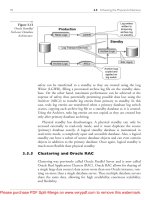
It is important to distinguish network topology from routing architecture. It is pos-
sible, for example, to have a single core system that spans multiple backbone networks.
The core machines can be programmed to hide the underlying architectural details and
to compute shortest routes among themselves. It is not possible, however, to partition
the core system into subsets that each keep partial information without losing func-
tionality. Figure
14.5
illustrates the problem.
default route to sites
default routes beyond core
1
default routes
from sites from sites
behind core
2
CORE
#l
CORE
#2
beyond core
2
Figure
145
An
attempt to partition a core routing architecture into two sets
of routers that keep partial information and use default routes.
Such
an
architecture results
in
a routing loop for datagrams that
have
an
illegal (nonexistent) destination.
As the figure shows, outlying routers have default routes to one side of the parti-
tioned core. Each side of the partition has information about destinations on its side of
the world and a default route for information on the other side of the world.
In
such an
architecture, any datagram sent to an illegal address will cycle between the two parti-
tions in a routing loop until its time to live counter reaches zero.
We can summarize as follows:
262
Routing: Cores,
Peers,
And Algorithms Chap.
14
A
core routing architecture assumes a centralized set of routers serves
as the repository of information about all possible destinations in an
internet. Core systems work best for internets that have a single, cen-
trally managed backbone. Expanding the topology to multiple back-
bones makes routing complex; attempting to partition the core archi-
tecture so that all routers use default routes introduces potential rout-
ing loops.
14.7 Automatic Route Propagation
We said that the original Internet core system avoided default routes because it
propagated complete information about
all
possible destinations to every core router.
Many corporate internets now use a similar scheme
-
routers in the corporation run
programs that communicate routing information. The next sections discuss two basic
types of algorithms that compute and propagate routing information, and use the origi-
nal core routing protocol to illustrate one of the algorithms.
A
later section describes a
protocol that uses the other type of algorithm.
It may seem that automatic route propagation mechanisms are not needed,
especial-
ly on small internets.
However, internets are not static. Connections fail and are later
replaced. Networks can become overloaded at one moment and underutilized at the
next. The purpose of routing propagation mechanisms is not merely to find a set of
routes, but to continually update the information. Humans simply cannot respond to
changes fast enough; computer programs must
be
used. Thus, when we
think
about
route propagation, it is important to consider the dynamic behavior of protocols and al-
gorithms.
14.8 Distance Vector (Bellman-Ford) Routing
The term
distance-vectod
refers to a class of algorithms routers use to propagate
routing information.
The idea behind distance-vector algorithms is quite simple. The
router keeps a list of all known routes
in
a table. When it boots, a router initializes its
routing table to contain an entry for each directly connected network. Each entry
in
the
table identifies a destination network and gives the distance to that network, usually
measured in hops (which will be defined more precisely later). For example, Figure
14.6
shows the initial contents of the table on a router that attaches to two networks.
tThe
tern
vector-distance, Ford-Fulkerson, Bellman-Ford,
and
Bellman
are
synonymous with
distance-
vector,
the last two are taken
from
the names of researchers who published the idea.
Sec.
14.8
Distance
Vector
(Bellman-Ford) Routing
Destination
I
Distance
I
Route
direct
Net 2
O
I
direct
Fire
14.6
An
initial distance-vector routing table with an entry for each
directly co~ected network.
Each
entry contains the
IP
address
of a network and an integer distance to that network.
Periodically, each router sends a copy of its routing table to any other router it can
reach directly. When a report arrives at router
K
from router
J,
K
examines the set of
destinations reported and the distance to each.
If
J
knows a shorter way to reach a des-
tination, or if
J
lists a destination that
K
does not have in its table, or if
K
currently
routes to a destination through
J
and J's distance to that destination changes,
K
replaces
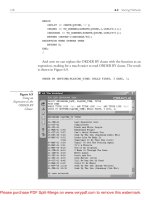
its table entry. For example, Figure
14.7
shows an existing table
in
a router,
K,
and
an
update message from another router,
J.
Destination
Net 1
Net
2
Net 4
Net 17
Net 24
Net 30
Net 42
Distance
0
0
8
5
6
2
2
(a>
Route Destination
direct
Net 1
direct
-
Net4
Router
L
Net 17
Router
M
-
Net 21
Router
J
Net 24
Router
Q
Net 30
Router
J
-
Net 42
Distance
2
3
6
4
5
10
3
Figure
14.7
(a)
An
existing route table for a router
K,
and
(b)
an
incoming
routing update message from router
J.
The marked entries will
be
used to update existing entries or add new entries to K's
table.
Note that
if
J
reports
distance
N,
an updated entry in
K
will have distance
N+I
(the
distance to reach the destination from
J
plus the distance to reach
J).
Of course, the
routing table entries contain a third column that specifies a next hop. The next hop en-
try
in
each initial route is marked
direct delivery.
When router
K
adds or updates an en-
try
in
response to a message from router
J,
it assigns router
J
as the next hop for that
entry.
The
term
distance-vector
comes from the information sent in the periodic mes-
sages.
A
message contains a list of pairs
(V,
D),
where
V
identifies a destination
(called the
vector),
and
D
is the distance to that destination. Note that distance-vector
algorithms report routes in the first person (i-e., we
think
of a router advertising,
"I
can
264
Routing: Cores,
Peers,
And Algorithms Chap.
14
reach destination
V
at distance
D").
In such a design, all routers must participate in the
distance-vector exchange for the routes to be efficient and consistent.
Although distance-vector algorithms are easy to implement, they have disadvan-
tages. In a completely static environment, distance-vector algorithms propagate routes
to all destinations. When routes change rapidly, however, the computations may not
stabilize. When a route changes
(i.e, a new connection appears or an old one fails), the
information propagates slowly from one router to another. Meanwhile, some routers
may have incorrect routing information.
For now, we will examine a simple protocol that uses the distance-vector algorithm
without discussing all the shortcomings. Chapter
16
completes the discussion by show-
ing another distance-vector protocol, the problems that can arise, and the heuristics used
to solve the most serious of them.
14.9
Gateway-To-Gateway Protocol (GGP)
The original core routers used
a
distance-vector protocol known as the
Gateway-
to-Gateway Protocolf (GGP)
to exchange routing information. Although GGP only
handled classful routes and is no longer part of the TCPJIP standards$, it does provide a
concrete example of distance-vector routing. GGP was designed to travel in
IP
da-
tagrams similar to UDP datagrams or TCP segments. Each GGP message has a fied
format header that identifies the message type and the format of the remaining fields.
Because only core routers participated in GGP, and because core routers were controlled
by a central authority, other routers could not interfere with the exchange.
The original core system was arranged to permit new core routers to be added
without modifying existing routers. When a new router was added to the core system,
it was assigned one or more core
neighbors
with which it communicated. The neigh-
bors, members of the core, already propagated routing information among themselves.
Thus, the new router only needed to inform its neighbors about networks it could reach;
they updated their routing tables and propagated this new information further.
GGP is a true distance-vector protocol. The information routers exchange with
GGP consists of a set of pairs,
(N,
D),
where
N
is an IP network address, and
D
is a
distance measured
in
hops.
We say that a router using GGP
advertises
the networks it
can reach and its cost for reaching them.
GGP measures distance in
router hops,
where a router is defined to be zero hops
from directly connected networks, one hop from networks that are reachable through
one other router, and so on. Thus, the
number of hops
or the
hop count
along a path
from a given source to a given destination refers to the number of routers that a da-
tagram encounters along that path. It should be obvious that using hop counts to calcu-
late shortest paths does not always produce desirable results. For example, a path with
hop count
3
that crosses three LANs may be substantially faster than a path with hop
count
2
that crosses two slow speed serial lines. Many routers use artificially high hop
counts for routes across slow networks.
?Recall that although vendors adopted the term
IP
router,
scientists originally used the term
IP
gateway.
$The
IETF
has declared GGP
historic,
which means that it is no longer recommended for
use
with
TCPAP.
Sec.
14.10
Distance Factoring
265
14.10 Distance Factoring
Like most routing protocols, GGP uses multiple message
types,
each with its own
format and purpose.
A
field in the message header contains a code that identifies the
specific message type; a receiver uses the code to decide how to process the message.
For example, before two routers can exchange routing information, they must establish
communication, and some message types are used for that purpose. The most funda-
mental message type in
GGP is also fundamental to any distance-vector protocol: a
routing update which is used to exchange routing information.
Conceptually, a routing update contains a list of pairs, where each entry contains
an
IP
network address and the distance to that network. In practice, however, many
routing protocols rearrange the information to keep messages small.
In
particular, ob-
serve that few architectures consist of a linear arrangement of networks and routers.
In-
stead, most are hierarchical, with multiple routers attached to each network. Conse-
quently, most distance values in an update are small numbers, and the same values tend
to
be
repeated frequently. To reduce message size, routing protocols often use a tech-
nique that was pioneered in GGP. Known as
distance factoring,
the technique avoids
sending copies of the same distance number. Instead, the list of pairs is sorted by dis-
tance, each distance value is represented once, and the networks reachable at that dis-
tance follow. The next chapter shows how other routing protocols factor information.
14.1 1 Reliability And Routing Protocols
Most routing protocols use connectionless transport. For example, GGP encapsu-
lates messages directly in
IP
datagrams; modem routing protocols usually encapsulate
in
UDP?. Both
IP
and UDP offer the same semantics: messages can be lost, delayed, du-
plicated, corrupted, or delivered out of order. Thus, a routing protocol that uses them
must compensate for failures.
Routing protocols use several techniques to handle delivery problems. Checksums
are
used to handle corruption. Loss is either handled by
sofr state$
or through ack-
nowledgement and retransmission. For example, GGP uses an extended acknowledge-
ment scheme in which a receiver can
return either a positive or negative acknowledge-
ment.
To handle delivery out of order and the corresponding reply that occurs when an
old message arrives, routing protocols often used
sequence numbers.
In GGP, for ex-
ample, each side chooses an initial number to use for sequencing when communication
begins.
The other side must then acknowledge the sequence number. After the initial
exchange, each message contains the next number in the sequence, which allows the re-
ceiver to know whether the message arrived in order. In a later chapter, we will see an
example of a routing protocol that uses soft state
infornlation.
tThere are exceptions
-
the next chapter discusses a protocol that uses
TCP.
:Recall that soft state relies on timeouts to remove old infornlation rather than waiting for a message
from
the
source.
266
Routing: Cores,
Peers,
And Algorithms Chap.
14
14.1
2
Link-State (SPF) Routing
The main disadvantage of the distance-vector algorithm is that it does not scale
well. Besides the problem of slow response to change mentioned earlier, the algorithm
requires the exchange of large messages. Because each routing update contains an entry
for every possible network, message size is proportional to the total number of networks
in an internet. Furthermore, because a distance-vector protocol requires every router to
participate, the volume of information exchanged can be enormous.
The primary alternative to distance-vector algorithms is a class of algorithms
known as
link state, link status,
or
Shortest Path Firstt (SPF).
The SPF algorithm re-
quires each participating router to have complete topology information. The easiest
way to think of the topology information is to imagine that every router has a map that
shows all other routers and the networks to which they connect.
In
abstract terms, the
routers correspond to nodes in a graph and networks that connect routers correspond to
edges. There is an edge (link) between two nodes
if
and only
if
the corresponding
routers can communicate directly.
Instead of sending messages that contain lists of destinations, a router participating
in an SPF algorithm performs two tasks. First, it actively tests the status of all neighbor
routers.
In
terms of the graph, two routers are neighbors if they share a link; in network
terms, two neighbors connect to a common network. Second, it periodically propagates
the link status information to all other routers.
To test the status of a directly connected neighbor, a router periodically exchanges
short messages that ask whether the neighbor is alive and reachable.
If
the neighbor re-
plies, the link between them is said to be
up.
Otherwise, the link is said to be
down$.
To inform
all
other routers, each router periodically broadcasts a message that lists the
status (state) of each of its links. A status message does not spec@ routes
-
it simply
reports whether communication is possible between pairs of routers. Protocol software
in the routers arranges to deliver a copy of each link status message to all participating
routers (if the underlying networks do not support broadcast, delivery is done by for-
warding individual copies of the message point-to-point).
Whenever a link status message arrives, a router uses the information to update its
map of the internet, by marking links up or down. Whenever link status changes, the
router recomputes routes by applying the well-known
Dijkstra shortest path algorithm
to the resulting graph. Dijkstra's algorithm computes the shortest paths to all destina-
tions from a single source.
One of the chief advantages of SPF algorithms is that each router computes routes
independently using the same original status data; they do not depend on the computa-
tion of intermediate machines. Because link status messages propagate unchanged, it is
easy to debug problems. Because routers perform the route computation locally, it is
guaranteed to converge. Finally, because link status messages only
carry information
about the direct connections from a single router, the size does not depend on the
number of networks in the internet. Thus, SPF algorithms scale better than distance-
vector algorithms.
?The name "shortest path first" is a misnomer because
all
routing algorithms
seek
shortest paths.
$In
practice, to prevent oscillations between the up and down states, most protocols use a
k-our-ofn
rule
to test liveness, meaning that the
link
remains up until a signif~cant percentage of requests have no reply, and
then it remains down until a significant percentage of messages receive a reply.
Sec.
14.13
Summary
14.13
Summary
To ensure that all networks remain reachable with high reliability, an internet must
provide globally consistent routing. Hosts and most routers contain only partial routing
information; they depend on default routes to send datagram to distant destinations.
Originally, the global Internet solved the routing problem by using a core router archi-
tecture in which a set of core routers each contained complete information about all net-
works. Routers in the original Internet core system exchanged routing information
periodically, meaning that once a single core router learned about a route, all core
routers learned about it. To prevent routing loops, core routers were forbidden from us-
ing default routes.
A
single, centrally managed core system works well for an internet architecture
built on a single backbone network. However, a core architecture does not suff~ce for
an internet that consists of a set of separately managed peer backbones that interconnect
at multiple places.
When routers exchange routing information they use one of two basic algorithms,
distance-vector or SPF.
A
distance-vector protocol, GGP, was originally used to pro-
pagate routing update information throughout the Internet core.
The chief disadvantage of distance-vector algorithms is that they perform a distri-
buted shortest path computation that may not converge
if
the status of network connec-
tions changes continually. Another disadvantage is that routing update messages grow
large as the number of networks increases.
The use of SPF routing predates the Internet. One of the earliest examples of an
SPF protocol comes from the ARPANET, which used a routing protocol internally to
establish and maintain routes among packet switches. The ARPANET algorithm was
used for a decade.
FOR FURTHER STUDY
The definition of the core router system and GGP protocol in this chapter comes
from Hinden and Sheltzer [RFC 8231. Braden and Postel [RFC 18121 contains further
specifications for Internet routers. Almquist [RFC 17161 summarizes later discussions.
Braun
[RFC
10931 and Rekhter
[RFC
10921 discuss routing in the NSFNET backbone.
Clark
W
11021 and Braun
[RFC
11041 both discuss policy-based routing. The next
two chapters present protocols used for propagating routing information between
separate sites and within a single site.
268
EXERCISES
Routing: Cores,
Peers,
And
Algorithms Chap.
14
Suppose a router discovers it is about to route an
IP
datagram back over the same net-
work interface on which the datagram arrived. What should it do? Why?
After reading
RFC
823
and
RFC
1812,
explain what an Internet core router (i.e., one
with complete routing information) should do in the situation described
in
the previous
question.
How can routers in a core system use default routes to send all illegal datagrams to a
specific machine?
Imagine students experimenting with a router that attaches a local area network to an in-
ternet that has a core routing system. The students want to advertise their network to a
core router, but
if
they accidentally advertise zero length routes to arbitrary networks,
traffic from the internet will be diverted to their router incorrectly. How can a core pro-
tect itself from illegal data while still accepting updates from such "untrusted" routers?
Which ICMP messages does a router generate?
Assume a router is using unreliable transport for delivery. How can the router determine
whether a designated neighbor is "up" or "down"? (Hint: consult
RFC
823
to find out
how the original core system solved the problem.)
Suppose two routers each advertise the same cost,
k,
to reach a given network,
N.
Describe the circumstances under which routing through one of them may take fewer to-
tal hops than routing through the other one.
How does a router know whether an incoming datagram carries a
GGP message?
An
OSPF message?
Consider the distance-vector update shown in Figure
14.7
carefully. For each item up
dated
in
the table, give the reason why the router will perform the update.
Consider the use of sequence numbers to ensure that two routers do not become con-
fused when datagrams are duplicated, delayed, or delivered out of order. How should
initial sequence numbers be selected? Why?