Part 4: Addressing Resolution & IP Routing ppsx
Bạn đang xem bản rút gọn của tài liệu. Xem và tải ngay bản đầy đủ của tài liệu tại đây (601.19 KB, 17 trang )
PITITHCM- Computer Network dept
Internal Using only 1
Computer Network
Part 4. Addressing Resolution & IP
Routing
• ARP
• R-ARP/ DHCP
• DNS
• IP Routing
– Concepts & terminologies
– Static & dynamic routing
– Routing algorithms
• Distance vector
• Link-state
– Routing protocols
• RIP
• OSPF
IP Infrastructure Services
IP Infrastructure Services
•IP best-effort packet-delivery service
– IP addressing and packet forwarding with datagram mode.
– Multiplexing accomplished by transport protocols (TCP, UDP)
• And how to build on top of the narrow waist
–Domain Name System (DNS) for resolution between name and
addresses
– Dynamic host configuration protocol-DHCP for IP
configurations
– build on below of the narrow waist: ARP for Destination MAC
address
•Glue (ARP, R-ARP/DHCP, DNS, ICMP)
• Security with end-system/ essential devices protection and data
privacy (NAT, firewalls)
• And how to get the traffic from internal to external
– Internet routing (Intra-domain and inter-domain)
Three Kinds of Identifiers for
Communication
• Host name (e.g., www.cnn.com)
– Mnemonic name appreciated
by humans
– Provides little (if any) information about location
– Hierarchical, variable # of alpha-numeric characters
• IP address (e.g., 64.236.16.20)
–Numericaladdress appreciated
by routers/ host
– Related to host’s current location in the topology
– Hierarchical name space of 32 bits
• MAC address (e.g., 00-15-C5-49-04-A9)
–Numericaladdress appreciated within local area network
– Unique, hard-coded in the adapter when it is built
– Flat name space of 48 bits
Mapping Between Identifiers
• Domain Name System (DNS)
– Given a host name, provide the IP address
– Given an IP address, provide the host name
• Dynamic Host Configuration Protocol (DHCP)
– Given a MAC address, assign a unique IP address
– Tell host other stuff about the Local Area Network
–IP Address
–Network Mask
– Default Router
To automate the boot-strapping process
• Address Resolution Protocol (ARP)
– Given an IP address, provide the MAC address
– To enable communication within the Local Area Network
Address Resolution Protocol (ARP)
Address Resolution Protocol (ARP)
• In order for devices to communicate, the sending
devices need both the IP addresses and the MAC
addresses of the destination devices.
• When they try to communicate with devices whose IP
addresses they know, they must determine the MAC
addresses.
• ARP enables a computer to find the MAC address of
the computer that is associated with an IP address.
ARP Flowchart
Send Data to a device
Send Data
Send an
ARP request
Get an
ARP reply
Is the
MAC address
in my ARP
cache
N
N
Y
Y
Insert the new record
into ARP cache
PITITHCM- Computer Network dept
Internal Using only 2
197.15.22.33
A.B.C.1.3.3
197.15.22.35
A.B.C.7.3.5
197.15.22.34
A.B.C.4.3.4
A
A
B
B
C
C
ARP operation: ARP request
MAC
A.B.C.1.3.3
MAC
ff.ff.ff.ff.ff.ff
IP
197.15.22.33
IP
197.15.22.35
What is your MAC Addr?
A Broadcast: who knows the
Ethernet address for 197.15.22.35?
10.0.2.1
A.B.C.1.3.3
10.0.2.9
A.B.C.7.3.5
10.0.2.5
A.B.C.4.3.4
A
A
B
B
C
C
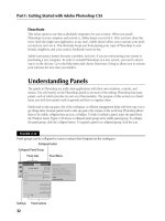
ARP Reply and Caching
MAC
A.B.C.7.3.5
MAC
A.B.C.1.3.3
IP
197.15.22.35
IP
197.15.22.33
This is my MAC Addr
C reply in Unicast : Yes, I am
A.B.C.7.3.5
ARP Table:
A.B.C.7.3.5 – 197.15.22.35
R
A
M
R
A
M
197.15.22.33
A.B.C.1.3.3
197.15.22.35
A.B.C.7.3.5
197.15.22.34
A.B.C.4.3.4
A
A
B
B
C
C
ARP Cache For Creating A Data Frame
ARP Table:
A.B.C.7.3.5 – 197.15.22.35
MAC
A.B.C.1.3.3
MAC
A.B.C.7.3.5
IP
197.15.22.33
IP
197.15.22.35
Data
Default gateway
• In order for a device to communicate with another device on
another network, you must supply it with a default gateway.
• A default gateway is the IP address of the interface on the
router that connects to the network segment on which the source
host is located.
• In order for a device to send data to the address of a device
that is on another network segment, the source device sends the
data to a default gateway.
A
R
P
R
e
p
l
y
Default
gateway
Eo
E
1
Reverse-ARP
Dynamic addressing
• There are a few different
methods that you can use to assign
IP addresses dynamically:
– RARP: Reverse Address Resolution
Protocol.
– BOOTP: BOOTstrap Protocol.
– DHCP: Dynamic Host Configuration
Protocol.
PITITHCM- Computer Network dept
Internal Using only 3
Solutions for dynamic assignment of IP
addresses
• Reverse Address Resolution Protocol -RARP
– Workstations running RARP have codes in ROM that
direct them to start the RARP process, and locate the
RARP server.
– Broadcast a request for the IP address associated with
a given MAC address
– RARP server responds with an IP address
– Only assigns IP address (not the default router and
subnetmask)
RARP
Ethernet MAC
address
(48 bit)
ARP
IP address
(32 bit)
BOOTP
• BOOTstrap Protocol (BOOTP)
• From 1985
• Host can configure its IP parameters at boot time.
•3 services.
– IP address assignment.
– Detection of the IP address for a serving machine.
– The name of a file to be loaded and executed by the client
machine (boot file name)
– Not only assign IP address, but also default router,
network mask, etc.
– Sent as UDP messages (UDP Port 67 (server) and 68
(host))
– Use limited broadcast address (255.255.255.255):
• These addresses are never forwarded
DHCP
• Dynamic Host Configuration Protocol (DHCP)
–From 1993
– An extension of BOOTP, very similar to DHCP
– Same port numbers as BOOTP
– Extensions:
• Supports temporary allocation (“leases”) of IP
addresses
• DHCP client can acquire all IP configuration
parameters needed to operate
– DHCP is the preferred mechanism for dynamic
assignment of IP addresses
– DHCP can interoperate with BOOTP clients.
IP address assignment
static addressing and dynamic addressing
Dynamic addressing: RARP
MAC: Known
IP: Unknown
MAC:
MAC:
Known
Known
IP:
IP:
Unknown
Unknown
RARP Request
RARP Request
RARP Reply
RARP Reply
RARP server
RARP server
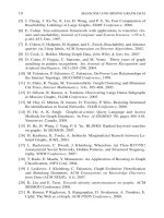
Dynamic addressing: DHCP
MAC: Known
IP: Unknown
MAC:
MAC:
Known
Known
IP:
IP:
Unknown
Unknown
DHCP Discover
DHCP Discover
UDP Broadcast
UDP Broadcast
DHCP Offer
DHCP Offer
UDP Broadcast
UDP Broadcast
DHCP server
DHCP server
IP1
IP2
IP3
IP
IP
1
1
IP
IP
2
2
IP
IP
3
3
DHCP Request
DHCP Request
DHCP Ack
DHCP Ack
Gateway
IP of other servers
And more …
Gateway
Gateway
IP of other servers
IP of other servers
And more …
And more …
IP Address
Lease time
DHCP sever IP
Address
IP Address
IP Address
Lease time
Lease time
DHCP sever IP
DHCP sever IP
Address
Address
PITITHCM- Computer Network dept
Internal Using only 4
DHCP Timeline Includes
the Lease Time (LT), Renewal
Time (T1), and Rebinding Time (T2)
Other options (selection)
• Other DHCP information that is sent as
an option:
Subnet Mask, Name Server, Hostname,
Domain Name, Forward On/Off, Default
IP TTL, Broadcast Address, Static
Route, Ethernet Encapsulation, X
Window Manager, X Window Font, DHCP
Msg Type, DHCP Renewal Time, DHCP
Rebinding, Time SMTP-Server, SMTP-
Server, Client FQDN, Printer Name, …
INIT
SELECTING
-/DHCPDISCOVER
DHCPOFFER/
Process offer
REQUESTING
Select offer/DHCPREQUEST
BOUND
DHCPACK/Set T1,T2
DHCPACK/Set T1,T2
DHCPACK/Set T1,T2
RENEWING
T1/
Unicast
DHCPREQUEST
REBINDING
T2/Broadcast DHCPREQUEST
DHCPNAK/
Stop using IP address
DHCPNAK,
Lease expires/
Stop using IP
address
DHCPACK (in use)/
DHCPDECLINE
DHCPNAK/
Discard offer
DHCP client Behavior
Detail
PITITHCM- Computer Network dept
Internal Using only 5
DHCP Relay Agents
• The relay agent function is typically loaded on a
router connected to the segment containing DHCP
clients
• This relay agent device is configured with the
address of the DHCP server, and can communicate
unicast directly with that server
DHCP Relay Agents
• Figure 8-11 shows the communication sequence on a
network that supports a DHCP relay agent
Summary
• The function of a subnet mask is to map the parts of an IP
address that are the network and the host
• Someday IPV4 will be completely obsolete and IPV6 will be
the commonly used version
• A computer must have an IP address to communicate on the
Internet
• An IP address may be configured statically or dynamically
• A dynamic IP address may be allocated using RARP, DHCP
• DHCP supplies more information to a client than BOOTP
• DHCP allows computers to be mobile allowing a connection to
many different networks
• ARP and Proxy ARP can be used to solve address resolution
problems
DNS
Domain Name Service
The Domain Name System
The Domain Name System
•The domain name system is usually used to translate a
host name into an IP address and vice versa.
• DNS comprises three main elements:
– Domain name space
– Name servers
–Resolver
• Domain name space
– A hierarchical and logical tree structure
– An inverted tree with the root node at the top
– Each node has a label- The root node has a null
label, written as “.”
Name Space
vnn
vnn
com
com
edu
edu
gov
gov
com
com
edu
edu
gov
gov
uk
uk
fr
fr
vn
vn
.
.
Root
www
www
abc
abc
• Domain names comprise a hierarchy so that names are
unique, easy to remember.
•Each host name is made up of a sequence of
labels
separated by periods.
•Examples:
– www.abc.edu.vn
PITITHCM- Computer Network dept
Internal Using only 6
DNS (Name) Servers
• DNS name servers with
DNS distributed database-
indexed by name
.
– Process of resolving names to IP addresses -
resolve forward lookup queries
– A reverse lookup query resolves an IP address to a
name -resolve reverse lookup queries
• a special second-level domain called in-addr.arpa
was created.
• Name Caching- Name server caching and that the
name server caches the query results to reduce the
DNS traffic on the network
Resolvers/ DNS Clients
• A DNS client is called a
resolver
. Which query name
servers about the name space
• Resolving Resolution
–Recursionrequests the name server to find out the
answer (possibly by contacting other servers).
– Iteration request the name server response may be
a list of other
name servers to contact.
DNS: System
vnn
vnn
com
com
edu
edu
gov
gov
com
com
edu
edu
gov
gov
uk
uk
fr
fr
vn
vn
.
.
.
.
DNS: Database
vn
vn
com
com
ctt
ctt
www.ctt.com.vn
203.162.50.100
www
203.162.4.10
203.162.50.1
203.162.0.1
63.63.0.1
www – 203.162.50.100
mail – 203.162.50.101
Lab – 203.160.100.1
www – 203.162.50.100
mail – 203.162.50.101
Lab – 203.160.100.1
ctt – 203.162.50.1
aaa – 203.162.70.201
bbb – 203.160.9.7
ctt – 203.162.50.1
aaa – 203.162.70.201
bbb – 203.160.9.7
DNS: Resolve www.yahoo.com
vnn
vnn
yahoo
yahoo
com
com
vn
vn
.
.
Address
of com
server
Address
of com
server
Address of
yahoo.com
server
Address of
yahoo.com
server
Address of
www.yahoo.com
Address of
www.yahoo.com
Address of
www.yahoo.com
Address of
www.yahoo.com
Request
Request
Request
Reply
Reply
Reply
Back…
IP Network Infrastructure For
Interconnection
IP ROUTING OVERVIEW
IP Network Infrastructure For
Interconnection
IP ROUTING OVERVIEW
PITITHCM- Computer Network dept
Internal Using only 7
Routing overview
• Routing is processes of finding the most efficient path
• Router with control plane and forwarding plane.
– Maintain routing tables / knowing of changes
– Datagram processing:
• Path determination:
– Choose the next hop basing on routing table
– Metric bases on bandwidth, hop, delay, load,
cost
•Packet switching:
– re-encapsulates
– then switches the packet out that port.
» switches the packets to the appropriate
interface -
Some Routing Concepts (1/2)
¾ Hierarchical routing in structure of ASs, Areas, networks
• Autonomous System: a collection of networks that falls
under the same administration domain.
– Connecting ASs are boundary routers
• Areas:
– The main units in AS
– Include in Networks and Sub-networks
– Connecting between areas are border routers
– Connecting between networks/ subnetworks in a area
are internal routers
• Interior Gateway Protocol (IGP): is used for exchanges of
routing information by routers located within an
autonomous system.
– Border routers run interior routing protocol with other
border routers
• Exterior Gateway Protocol (EGP
): The Exterior Gateway
Protocol is used for exchanging routes between two
autonomous systems.
– Boundary routers run exterior routing protocol with
other gateway routers
Some Routing Concepts (2/2)
Intra-AS and Inter-AS routing
Host
h2
a
b
b
a
a
C
A
B
d
c
A.a
A.c
C.b
B.a
c
b
Host
h1
Intra-AS routing
within AS A
Inter-AS
routing
between
A and B
Intra-AS routing
within AS B
Internet: OSPF, IS-IS, RIP
Internet: BGP
Routing Fundamentals (1/2)
• Routing table contain of routing information.
• A router learns paths (routes), from the
static
configuration entered by an administrator or
dynamically
from other routers, through routing protocols.
• Routers keep a routing table in RAM.
• A routing table is a list of the best known available
routes.
• Routers use this table to make decisions about how to
forward a packet.
Routing Fundamentals (2/2)
•Static routing – An administrator manually defines
routes to one or more destination networks.
•Static routing is not suitable for large, complex
networks that include redundant links, multiple protocols,
and meshed topologies.
•Dynamic routing – used in complex networks must adapt
to topology changes quickly and select the best route
from multiple candidates.
PITITHCM- Computer Network dept
Internal Using only 8
Basic Dynamic Routing Methods
•Source-based:source gets a map of the network,
– source gives a list of routes to reach destination
– signals the route-setup (eg: ATM , Frame relay approach)
•Hop by Hop:
routers determine e best next hop to a
destination
–Link statewith least-cost path calculated using global
knowledge about network
• Maps consistent => next-hops consistent
•OSPF; BGP
–Distance vector:least-cost path calculated in an
iterative, distributed manner
• begins with a cost of the directly attached links
• info exchange with the neighbouring nodes
• RIP; IGP
Approaches to Routing – Distance-vector
• Each node (router or host) exchange information with
adjacent nodes (nodes directly connected to same
network)
• Node maintains vector of link costs for each directly
attached network and distance and next-hop vectors
for each destination
• Bellman Ford Algorithm used by Routing Information
Protocol (RIP)
• Requires transmission of lots of information by each
router
– Distance vector to all neighbors
– Contains estimated path cost to all networks
– Changes take long time to propagate
Static Routing
and
Dynamic Routing
Routing Fundamentals
• Routing table contain of routing information.
• A router learns paths, or routes, from the
static
configuration entered by an
administrator or
dynamically
from other
routers, through routing protocols.
• Routers keep a routing table in RAM. A
routing table is a list of the best known
available routes. Routers use this table to
make decisions about how to forward a
packet.
ARP tables and Routing tables
Static Routing
_ Static routing is useful in networks that do not have
multiple paths to any destination network.
_ Administrators often configure static routes on access
routers that connect stub networks. Stub networks have
only one way in and one way out.
_ Router(config)#
ip route destination-prefix
destination-prefix-mask
{next
address
|
interface
}
[
distance
]
PITITHCM- Computer Network dept
Internal Using only 9
Static routing
Static routing also is used by security reason.
Static routing is not suitable for large, complex networks
that include
redundant links, multiple protocols, and
meshed topologies
.
Routers in complex networks must adapt to topology
changes quickly and select the best route from multiple
candidates. Therefore, dynamic routing is the better
choice.
Dynamic routing
• Routers use metrics to evaluate, or measure, routes.
• When multiple routes to the same network exist and
the routes are from the same routing protocol, the
route with the lowest metric is considered the best
.
• Each routing protocol calculates
its metrics
differently.
Due to Routing protocol’s criteria, as: Bandwidth;
Delay; Load; Reliability; MTU…
Routing Protocol
• Routing protocols allow routers to choose the best path for
data from source to destination.
• Functions includes the following:
– Provides processes for sharing route information.
– Allows routers to communicate with other routers to update
and maintain the routing tables
Composite Routing metrics
• Bandwidth – The data capacity of a link.
• Delay – The length of time required to
move a packet along each link from
source to destination.
• Load – The amount of activity on a
network resource such as a router or a
link.
• Reliability – Usually a reference to the
error rate of each network link.
Default Route
• Default routes are used when the router cannot match a destination
network with a specific entry in the routing table. The router must use
the default route, or the gateway of last resort, to send the packet to
another router.
•Using default routes keep routing tables small is a key scalability
feature. They make it possible for routers to forward packets
destined to any Internet host without having to maintain a table entry
for every destination network.
• Default routes can be statically entered by an Admin or dynamically
learned through a routing protocol.
Finding path Algorithms
Distance Vector & Link State
PITITHCM- Computer Network dept
Internal Using only 10
Routing
vs.
Forwarding
Forwarding: select an output port based on destination
address and routing table
Data-plane function
Often implemented in hardware
Routing: process by which routing table is
built and
maintained
so that the series of local forwarding decisions
takes the packet to the destination with high
probability, and reachability
condition.
the path chosen/resources consumed by the
packet is
efficient
in some sense (optimality and
filtering condition)
Control-plane function
Implemented in software
Interconnection
Devices
H H
B
H H
Router
Extended LAN
=Broadcast
domain
LAN=
Collision
Domain
Network
Datalink
Physical
Transport
Router
Bridge/Switch
Repeater/Hub
Gateway
Application
Network
Datalink
Physical
Transport
Application
Routing problem
• Collect, process, and condense global state into local
forwarding information
• Global state
– inherently large
–dynamic
– hard to collect
•
Hard issues:
–
Consistency+ completeness (convergence time),
scalability (interior / exterior )
–Impact of resource needs of sessions
Consistency
•Defn: A series of
independent
local forwarding decisions must
lead to connectivity between any desired (source, destination)
pair in the network.
• If the states are inconsistent, the network is said not to have
“
converged
” to steady state (I.e. is in a transient state)
– Inconsistency leads to
loops
, wandering packets etc
– In general a part of the routing information may be
consistent while the rest may be inconsistent.
–Large networks => inconsistency is a scalability issue.
• Consistency can be achieved in two ways:
– Fully distributed approach:
a consistency criterion or
invariant across the states of adjacent nodes
– Signaled approach:
the signaling protocol sets up local
forwarding information along the path (SS7; RSVP…).
Completeness
•
Define:
The network as a whole and every node has
sufficient information to be able to compute
all
paths.
– In general, with more information available locally,
routing algorithms tend to converge faster, because
the chances of inconsistency reduce.
– But this means that more distributed state must be
collected at each node and processed.
– The demand for completeness also limits the scalability
of the algorithm.
• Since both consistency and completeness pose scalability
problems, large networks have to be structured
hierarchically and abstract entire networks as a single
node.
Global & decentralized routing algorithms
1. Global routing algorithm
• least-cost path calculated using global knowledge about
network
•input:connectivity between all nodes & link costs
• Link state algorithms
2. Decentralized routing algorithm
• least-cost path calculated in an iterative, distributed
manner
• no node has complete info about the costs of all
network links
• begins with a cost of the directly attached links
• info exchange with the neighbouring nodes
• Distance vector algorithms
PITITHCM- Computer Network dept
Internal Using only 11
Basic Dynamic Routing Methods
•Source-based:source gets a map of the network,
– source finds route, and either
– signals the route-setup (eg: ATM approach)
– encodes the route into packets (inefficient)
•Link state
routing:
per-link
information
–Get
map
of network (in terms of
link states
) at all
nodes and find next-hops locally.
– Maps consistent => next-hops consistent
•Distance vector
:
per-node
information
– At every node, set up
distance signposts
to
destination nodes (a vector)
– Setup this by peeking at neighbors’ signposts.
Approaches to Routing – Distance-vector
• Each node (router or host) exchange information with
neighboring nodes
– Neighbors are both directly connected to same
network
• Node maintains vector of link costs for each directly
attached network and distance and next-hop vectors
for each destination
• Used by Routing Information Protocol (RIP)
• Requires transmission of lots of information by each
router
– Distance vector to all neighbors
– Contains estimated path cost to all networks
– Changes take long time to propagate
Approaches to Routing – Link-state
• Designed to overcome drawbacks of distance-vector
• When router initialized, it determines link cost on each
interface
• Advertises set of link costs to all other routers in topology
– Not just neighboring routers
•Monitor link costs
– If significant change, router advertises new set of link
costs
• Each router can construct topology of entire configuration
– Can calculate shortest path to each destination network
• Router constructs routing table, listing first hop to each
destination
•Router does not use distributed routing algorithm
– Use any routing algorithm to determine shortest paths
–In practice, Dijkstra's algorithm
• Open shortest path first protocol uses link-state routing.
Least Cost Algorithms
• Least-cost criterion
– If minimize number of hops, link value 1
– Link value may be inversely proportional to
capacity (MTU), proportional to current load,
or some combination of BW, Reliability…
– May differ in different two directions
• length of queue
• Cost of path between two nodes as sum of
costs of links traversed
• For each pair of nodes, find least cost path
– Dijkstra's algorithm
– Bellman-Ford algorithm
DV & LS: consistency criterion
•
The subset of a Least path cost is also the
Least path cost between the two intermediate
nodes.
• Corollary:
– If the Least path cost from node i to node j, with
distance D(i,j) passes through neighbor k
, with link
cost c(i,k), then:
D(i,j) = c(i,k) + D(k,j)
i
k
j
c
(
i
,
k
)
D
(
k
,
j
)
Bellman Ford Algorithm
and
Distance Vector
PITITHCM- Computer Network dept
Internal Using only 12
Bellman-Ford Algorithm
• Find Least path costs from source node such that
paths contain at most one link
• Find Least path costs
such that paths have at most two
links
•And so on
Bellman-Ford Equation
• Distance vector based on
distributed
implementation of
Bellman-Ford algorithm
• Bellman-Ford equation:
• Label routers i=A, B, C, …
• Let D(i,j) = distance for best route from i to remote j
• Let d(i,j) = distance from router i to neighbor j
•Set to 0 if i=j or to infinity if i and j not adjacent
neighbors
4
3
6
2
1
9
1
1
D
A
F
E
B
C
Bellman-Ford Equation (2)
• Bellman-Ford equation:
• D(i,j) = min {d(i,k) + D(k,j)} for all i<>j
k is adjacent neighbors to i
• Ex. D(B,F) = min {d(B,k) + D(k,F)}
i=B; j=F and k=A,C,E
4
3
6
2
1
9
1
1
D
A
F
E
B
C
Bellman-Ford Algorithm
• Bellman-Ford equation:
• D(i,j) = min {d(i,k) + D(k,j)} for all i<>j
k neighbors
• Bellman-Ford
Algorithm
solves B-F
Equation
:
• To calculate D(i,j), node i only needs d(i,k)’s and
D(k,j)’s from neighbors
•Problem: don’t know D(k,j)’s
•Solution:
• For each node i, first find shortest distance
path from i to j
using one link
, D(i,j)[1]
• Shortest distance path
using two or fewer
links
, D(i,j)[2], must depend on the shortest
distance path using one link, namely D(i,j)[2] =
min {d(i,j) + D(i,j)[1]}
Bellman-Ford Algorithm (2)
Key observation: By induction, the best (h+1 or fewer)-
hop path between nodes i and j must be arise from an i-
to-neighbor link connected with a (h or fewer)-hop path
from neighbor to j :
If there are m nodes From I to j then I has to jump
(m+1) hops to reach j. call h=m
• Bellman-Ford
Algorithm
:
• D(i,j)[h+1] = min {d(i,k) + D(k,j)[h]} for all i<>j, h=0,1, …
k adjacent neighbors
• Iterate h=0,1,2, … until reach diameter h+1 of graph
•D(i,j)[h+1] is the originally desired B-F solution D(i,j)
•At each h, calculate D(i,j)[h+1] for all i<>j
• At h=0, D(i,j)[0] = {0 for i=j, infinity otherwise}
• D(i,i)[h] = link cost on which dist. vector is sent - 1
Bellman-Ford Algorithm Example (1)
• Suppose C wants to find shortest path to each
destination. Similarly to others
•First,calculate shortest one-link paths from
each
node: easy, D(i,j)[1]=d(i,j)
4
3
6
2
1
9
1
1
D
A
F
E
B
C
–D(C,B)[1], D(C,D)[1], and
–D(B,A)[1], D(B,E)[1],
D(B,C)[1], and
–D(D,E)[1], D(D,C)[1], and
–D(A,B)[1], D(A,E)[1],
D(A,F)[1], and
–D(E,A)[1], D(E,B)[1],
D(E,D)[1], D(E,F)[1], and
–D(F,A)[1], D(F,E)[1]
PITITHCM- Computer Network dept
Internal Using only 13
Bellman-Ford Algorithm Example (2)
•Second,calculate shortest with h=2 or fewer hop paths
from each node:
•Example: for node C to F
D(C,F)[2] = min (d(C,k) + D(k,F)[1]) for all j
k = B or D are adjacent neighbors
= min {d(C,B) + D(B,F)[1], d(C,D) + D(D,F)[1]}
4
3
6
2
1
9
1
1
D
A
F
E
B
C
• No one-link path from B to
F, so D(B,F)[1] is infinity,
same for D(D,F)[1]
• Calculate D(i,j)[2] for all
other combinations of i<>j
•Like D(B,F)[2] , D(D,F)[2]
Bellman-Ford Algorithm Example (3)
• Third, calculate shortest 3-or-fewer hop paths
from each node:
• Example: for node C to F
D(C,F)[3] = min {d(C,B) + D(B,F)[2], d(C,D) + D(D,F)[2]}
• No more unknowns:
• D(B,F)[2] is known by now and was calculated in the last
iteration, = min{d(B,k) + D(k,F)[1]}
• D(D,F)[2] is also known
4
3
6
2
1
9
1
1
D
A
F
E
B
C
• Since diameter = 3,
we’re done and have
found all shortest
distance paths D(i,j)
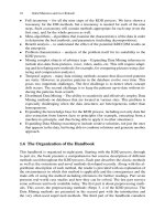
Example
Router A Router B
Router C Router D
10.0.2.0/24 10.0.3.0/24 10.0.4.0/24 10.0.5.0/2410.0.1.0/24
.1.2.2.2.2 .1.1.1
Assume: - link cost is 1, i.e., c(v,w) = 1
- all updates, updates occur simultaneously
- Initially, each router only knows the cost of
connected interfaces
t=0:
10.0.1.0 - 0
10.0.2.0 - 0
Net via
cost
t=0:
10.0.2.0 - 0
10.0.3.0 - 0
Net via
cost
t=0:
10.0.3.0 - 0
10.0.4.0 - 0
Net via
cost
t=0:
10.0.4.0 - 0
10.0.5.0 - 0
Net via
cost
t=1:
10.0.1.0 - 0
10.0.2.0 - 0
10.0.3.0 10.0.2.2 1
t=2:
10.0.1.0 - 0
10.0.2.0 - 0
10.0.3.0 10.0.2.2 1
10.0.4.0 10.0.2.2 2
t=2:
10.0.1.0 10.0.2.1 1
10.0.2.0 - 0
10.0.3.0 - 0
10.0.4.0 10.0.3.2 1
10.0.5.0 10.0.3.2 2
t=1:
10.0.1.0 10.0.2.1 1
10.0.2.0 - 0
10.0.3.0 - 0
10.0.4.0 10.0.3.2 1
t=2:
10.0.1.0 10.0.3.1 2
10.0.2.0 10.0.3.1 1
10.0.3.0 - 0
10.0.4.0 - 0
10.0.5.0 10.0.4.2 1
t=1:
10.0.2.0 10.0.3.1 1
10.0.3.0 - 0
10.0.4.0 - 0
10.0.5.0 10.0.4.2 1
t=2:
10.0.2.0 10.0.4.1 2
10.0.3.0 10.0.4.1 1
10.0.4.0 - 0
10.0.5.0 - 0
t=1:
10.0.3.0 10.0.4.1 1
10.0.4.0 - 0
10.0.5.0 - 0
Example
Router A Router B
Router C Router D
10.0.2.0/24 10.0.3.0/24 10.0.4.0/24 10.0.5.0/2410.0.1.0/24
.1.2.2.2.2 .1.1.1
t=3:
10.0.1.0 - 0
10.0.2.0 - 0
10.0.3.0 10.0.2.2 1
10.0.4.0 10.0.2.2 2
10.0.5.0 10.0.2.2 3
Net via
cost
t=3:
10.0.1.0 10.0.2.1 1
10.0.2.0 - 0
10.0.3.0 - 0
10.0.4.0 10.0.3.2 1
10.0.5.0 10.0.3.2 2
Net via
cost
t=3:
10.0.1.0 10.0.3.1 2
10.0.2.0 10.0.3.1 1
10.0.3.0 - 0
10.0.4.0 - 0
10.0.5.0 10.0.4.2 1
Net via
cost
t=3:
10.0.1.0 10.0.4.1 3
10.0.2.0 10.0.4.1 2
10.0.3.0 10.0.4.1 1
10.0.4.0 - 0
10.0.5.0 - 0
Net via
cost
Now, routing tables have converged !
t=2:
10.0.1.0 - 0
10.0.2.0 - 0
10.0.3.0 10.0.2.2 1
10.0.4.0 10.0.2.2 2
t=2:
10.0.1.0 10.0.2.1 1
10.0.2.0 - 0
10.0.3.0 - 0
10.0.4.0 10.0.3.2 1
10.0.5.0 10.0.3.2 2
t=2:
10.0.1.0 10.0.3.1 2
10.0.2.0 10.0.3.1 1
10.0.3.0 - 0
10.0.4.0 - 0
10.0.5.0 10.0.4.2 1
t=2:
10.0.2.0 10.0.4.1 2
10.0.3.0 10.0.4.1 1
10.0.4.0 - 0
10.0.5.0 - 0
Characteristics of Distance Vector Routing
• Periodic Updates: Updates to the routing tables are
sent at the end of a certain time period. A typical
value is 90 seconds.
• Triggered Updates: If a metric changes on a link, a
router immediately sends out an update without
waiting for the end of the update period.
• Full Routing Table Update: Most distance vector
routing protocol send their neighbors the entire
routing table (not only entries which change).
• Route invalidation timers: Routing table entries are
invalid if they are not refreshed. A typical value is to
invalidate an entry if no update is received after 3-6
update periods.
The count-to-infinity problem
• Suppose all distance vectors sent at once ; Suppose that A was down (link
cost = ∝) and it just came up and a metric is the number of hops
“If node X tells Y that it has a path somewhere, Y has no way of knowing
whether it itself is on the path.”
How can we avoid this problem?
They still think that A is down
so they will learn from B the
route to A after that
DVR -> bad news spread slowly
•DVR – good news spread rapidly
PITITHCM- Computer Network dept
Internal Using only 14
How can the Count-to-Infinity
problem be solved?
• Solution 1:
– Always advertise the entire path in an update
message (Path vectors)
– If routing tables are large, the routing messages require
substantial bandwidth
– BGP uses this solution
• Solution 2:
– Insight: It’s not useful to claim reachability for a
destination to the neighbor from which the route was
learned
– Don’t report routes back to node from which the
route was learned
– E.g. If I hear from X has the shortest route to Y,
don’t report to X I have a route to Y
Solution 3: Split Horizon with Poisoned
Reverse
AB CDE
inf. 2 3 4
inf. 2 3 4
inf. inf. 3 4
inf. inf. inf. 4
inf. inf. inf. inf.
B learns A is dead
After 1 exchange
After 2 exchanges
After 3 exchanges
B reports to C that
A’s metric is inf.
inf.
Report “split-horizon” routes as infinity to break
loops on the first routing exchange.
Link State (LS) Approach
•The
link state (Dijkstra) approach is iterative, but it
pivots around destinations j, and their predecessors k =
p(j)
– Observe that an alternative version of the
consistency condition holds for this case:
D(i,j) = D(i,k) + c(k,j)
– Each node i collects all link states c(*,*) first and
runs the complete Dijkstra algorithm locally.
i
k
j
c
(
k
,
j
)
D
(
i
,
k
)
Dijkstra Algorithm and Link State
Dijkstra's Algorithm – definitions
• n = set of nodes in the network
•s = source node
•SPT = {
a
} : set of nodes so far incorporated
(into a tree SPT)
•
m = n -SPT
• L(n) = least path cost from s to n
(n is node currently known)
– At termination, cost of least-cost path in graph
from s to n
– L(s,n) = 0 if s=n
– L(s,n) = ∞ if nodes not directly connected
– L(s,n) ≥ 0 if nodes directly connected
SPT Algorithm (Dijkstra)
(shortest path tree)
SPT = {
a
}
for all nodes
v
if
v
adjacent to
a
then L
(v)
= cost (a, v)
else L
(v) = infinity
Loop
find x
not in SPT, where L
(x)
is min [L(m)]; m not in
SPT
add
x
in SPT
for all
v
adjacent to
x
and not in SPT
L(v) = min [L(v), L(x) + C(x, v)]
until all nodes are in SPT
Dijkstra’s Algorithm: Example
(T=Tree, L(m): least path cost from source to m, p(n): Predecessor node)
Step
0
1
2
3
4
5
start T
A
AD
ADE
ADEB
ADEBC
ADEBCF
L(B),p(B)
2,A
2,A
2,A
L(C),p(C)
5,A
4,D
3,E
3,E
L(D),p(D)
1,A
L(E),p(E)
infinity
2,D
L(F),p(F)
infinity
infinity
4,E
4,E
4,E
A
E
D
CB
F
2
2
1
3
1
1
2
5
3
5
[Update Least-Cost Paths]
L(n) = min[L(n), L(x) + c(x, n)] for all n not in T
Find neighboring node Xnot in Twith
least-cost path from s, ie:L(m)=L(D).
=> Choose D among B,C,D
L(n) = L(n),
L(n) = L(x) + c(x, n)
PITITHCM- Computer Network dept
Internal Using only 15
Link-state concept
RFC 1583
contains a
description of
OSPF link-state
concepts and
operations.
Dijkstra’s
algorithm
Link State Algorithm
Flooding:
1) Periodically distribute link-state
advertisement (LSA) to neighbors
- LSA contains delays to each neighbor
2) Install received LSA in LS database (
LSDBs)
3) Re-distribute LSA to all neighbors
Path Computation
1) Use Dijkstra’s shortest path algorithm
to compute distances to all destinations
2) Install <destination, nexthop> pair in
forwarding table
Two link-state concerns
• Processing and memory requirements
• Bandwidth requirements
Link State Protocols
• Key: Create a network “
map
” at each node.
• 1. Node collects the state of its connected links
and forms a “Link State Packet” (LSP)
•2. Flood LSP => reaches every other node in the
network and everyone now has a network map.
• 3. Given map, run Dijkstra’s shortest path
algorithm (SPF) => get paths to all destinations
• 4. Routing table = next-hops of these paths.
• 5. Hierarchical routing: organization of areas,
and filtered control plane information flooded.
Hierarchical routing protocols
• The Internet uses hierarchical routing
– it is split into Autonomous Systems (AS)
• routers at the border: gateways
• gateways must run both intra & inter AS routing
protocols
– routers within AS run the same routing algorithm
• the administrator can chose any Interior Gateway
Protocol
– Routing Information Protocol (RIP)
– Open Shortest Path First (OSPF)
– between AS gateways use Exterior Gateway Protocol
• Border Gateway Protocol (BGP)
Firewall
IP Network Infrastructure for
IP Network Infrastructure for
protecting internal network
protecting internal network
PITITHCM- Computer Network dept
Internal Using only 16
IP Network Infrastructure
for Security- Firewall
IP Network Infrastructure
for Security- Firewall
• A firewall is a system or group of systems that enforces
an access control policy between networks.
• A firewall could comprises the following components as:
–Packet Filter
–NAT
–Proxy
•Functions:
– Blocking & permitting traffic
–Enabling secure remote connections (VPN)
– Content filtering (blocking): viruses, attacks
– Logging traffic
Packet Filtering (1/2)
• Filtering based on network layer of the IP stack
• Default permit or default deny design
• A good packet filter:
- Permits connections to really-needed services
- Filters out all the services what we do not use
currently (not only those we don’t want to show)
employees (stateless).
-Detects anomalies – TCP packet without SYN
handshake etc (stateful).
Packet Filtering (2/2)
• Packet filtering rules mostly based on:
– IP protocol (UDP, TCP, …)
– Source IP address
– Destination IP address
– Source/Destination port (socket)
– Connection state (TCP: SYN, RST, established,… or
e.g. FTP states)
– Incoming/outgoing interface
–etc.
FW as a single Packet Filter
Internet
router
firewall
Internal network
filters the traffic
it can be a dual-homed gateway or
a simple packet filter –
screening router
•Most routers
have packet
filtering
capabilities
NAT - Network Address Translation
•Solving limited number of publish IP addresses
available to an enterprise network.
• Limiting people's use of a connection by Ips,
though “gateways” have for the most part
nullified that feeble attempt.
• Hiding internal topology and services to out-
side
• Maps Internet IP Addresses to Private LAN IP
Addresses
NAT- Functions
• Many-to-one NAT (Dynamic NAT)
–Maps many private LAN IP Addresses to a single
Internet address or a pair of public IP address and
port number
–Dynamic NAT helps to secure a network as it masks the
internal configuration of a private network and makes
it difficult for someone outside the network to monitor
individual usage patterns.
• One-to-one NAT (Static NAT)
–Maps one private IP Address to one Internet IP
Address
– This allows an internal host, such as a Web server, to
have an unregistered (private) IP address and still be
reachable over the Internet.
PITITHCM- Computer Network dept
Internal Using only 17
NAT
Internet
Inside
10.4.4.5
10.1.1.1
Outside
Inside Local
IP Address
10.1.1.1
10.4.4.5
Inside Global IP
Address
192.2.2.2
192.3.3.6
NAT Table
SA
192.2.2.2
SA
10.1.1.1
Application Gateway- Proxy
• Proxies rebuild the whole protocol (application layer
gateway)
• Needs to know the exact specification of the protocol
we use
•Can investigate the content of the flow
• Can protect against protocol errors
• More vulnerable to DoS
• Can be more complicated to (internal) users (e.g. telnet
proxy)
¾ Lower performance but Higher security
Proxy operates with corresponding layers
Proxy operates with corresponding layers
Layers Networking Devices
• Application Application-layer proxy
• Presentation Circuit-level proxy
• Session Circuit-level proxy
• Transport Circuit-level proxy
• Network Router
• Data-Link Bridge
•Physical Hub/repeater
For performance responsibility
For security responsibility
Circuit-level proxy works as a gateway at transport
layer
Proxy and Caching
102
References:
1. Data- Computer Communication handbook-
William Stallings
2. TCP/IP Illustrated, Volume I - W.R. Stevens
3. CCNA- semester1-2-3-4
4. Internetworking Technology Overview
Cisco Systems