Lecture Notes in Computer Science- P61 pptx
Bạn đang xem bản rút gọn của tài liệu. Xem và tải ngay bản đầy đủ của tài liệu tại đây (259.79 KB, 5 trang )
A Virtual Laboratory Platform Based on Integration of Java and Matlab 289
To realize these functions of the JMPS, we utilize Java Socket and multi-thread
technology to solve these problems which are involved in listening to remote clients'
requests and multi-users access. A TCP/IP Socket connection is implemented between
Bean component and JMPS. By using the connection, the results and the remote cli-
ents' requests can be transmitted in stream format. Once one request is accepted suc-
cessfully, a new thread will be started to maintain the connection between the server
and the client. Bean component holds a client socket and JMPS holds a server socket
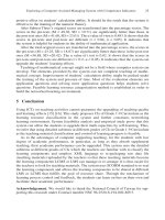
correspondingly. The definition of JMPS is shown in Fig.3.
Fig. 3. Definition of JMPS
Native methods make it possible to use Matlab’s computational engine inside the
user’s own Java applications, applets, and servlets as JMatLink connects Java and
Matlab. JMatLink uses Java JNI technique to locate and call non-java methods. First
of all, it compiles C/C++ source files, and then changes these files into Dynamic Link
Library (DLL) and imports Matlab library functions so that these functions can be
easily called. As a result, Matlab engine functions can be used from a Java program
by implementing engine function calls in C language native methods
. Detailed proc-
ess of communication between JMPS and Matlab is shown in Fig. 4. JMPS start a
JMatLink.c
Fig. 4. Communication between JMPS and Matlab
290 Y. Sheng et al.
thread when detecting a request from a component. Then the thread analyses the data
stream from the component to obtain data to be processed and component informa-
tion, which plays a role in locating and calling a certain function of Matlab. Finally,
the thread sends the data into computing engine of Matlab. Such kind of realization is
implemented by engine object which supports multi-users’ calls. The thread executes
method of the object and passes parameters in command line to Matlab for further
processing and the results will back to clients.
4.2 The Implementation of Client
The main functions in client side include offering friendly experiment interface and
assembling an experiment flow in the interface, adjusting parameters of the device,
running the program according to the flow and displaying the results, dynamically
registering the experiment components, saving the experiment flow and giving online
prompts, etc.
In the process of designing user interface, we adopted pure Java technology to de-
velop several classes. It mainly consists of MainWindow class, MainMenu class,
ToolBar class, DeviceCarrier class, RegisterClassPane class and DeviceConnector
class. The relation among them is shown in Fig. 5.
In the client, users could either choose the equipment components from the ex-
periment device list, or add and register new components at local. Therefore, it is
required that the components should be easily developed and have high efficient.
According to these characteristics, we adopt the component technology during the
development of equipment component in VL-JM platform. The JavaBeans technol-
ogy, which binds Java technology and component technology, make the development
of the Java program fast, easy and apt to maintain. All the devices in VL-JM platform
are developed according to the JavaBeans standard. All components provide the ex-
ternal call interfaces. Its implementation is encapsulated in each Bean, so that the user
could add their device components. The “get” and “set” methods in Beans component
could provide access and modification of its attribution. In this way, the operation on
setting and reading of the attribution of the experiment components could be
achieved.
PropertyEditor
ResultPane
MainWindow
DeviceCarrier
RegisterClassPane
DesignPane DeviceConnector
ToolBar
Button
MainMenu
MenuItem
Fig. 5. User interface window class
A Virtual Laboratory Platform Based on Integration of Java and Matlab 291
Using the Beans component technology, users could dynamically choose the
equipments, assemble experiment flow as well as set the parameters of the experi-
ment. While the event response and communication approach could be utilized for the
data interaction and communication between the components in VL-JM platform.
Fig.6. demonstrates the pattern of creating Beans component in our VL platform.
Fig. 6. Pattern of Beans component
Fig. 7. Connection between components and Matlab
When writing source codes, according to the pattern of the component, we only
need fulfil the algorithm, which achieves the equivalent functions of actual equip-
ments, of accomplishing equipment facility by the Beans component methods. We
adopt some relevant algorithms in Matlab to realize the corresponding functions. The
VL-JM platform integrates the JMatLink call Matlab algorithms into the Bean com-
ponents, which can get the results outputted by Matlab to the method of components
through JMPS. The relationship of them is shown in Figure 7.
5 Digital Communication Virtual Laboratory
Digital communication is an elementary course for undergraduate in many speciali-
ties, in which experiments are essential. In order to provide an effective and interac-
tive experiment environment with abundant instrument components in Internet, we
developed and realized the digital communication virtual lab on VL-JM platform.
We take the low-pass filter experiment for example to introduce how to develop
device components in the client and how the JMPS responds to user’s requests and
invokes functions in Matlab.
292 Y. Sheng et al.
public class FIRLowFilter {
/* Bean s method is used to send request to call lowFilter method */
public double[] lowPass(double[] value){
output=new ObjectOutStream(client.getOutputStream());
output.writeObject(
lowFilter + . +outputStr);
output.flush();
input=new ObjectInputSteam(client.getInputStream());
inputStr=(String)input.readObject(); //get result return through JMS
//parse
}
//displayData array will be prepared for interacting with next Bean
return this.displayData;
}
Fig. 8. The part of low-pass filter component
Fig
. 9. The implementation of calling functions in Matlab
Fig. 10. Experimental interface window
In the client, the design and realized codes of the low-pass filter component is
shown in Fig.8. In the method named lowPass, the double array is used for storing the
data which is sent back after invoking Matlab function. The data in the array will be
A Virtual Laboratory Platform Based on Integration of Java and Matlab 293
Fig. 11. Result of the experiment
processed and then be transmitted to the next components until it reaches the final one
of the whole experiment flow. When users set the experiment flow and push the “run”
button, the system will send a communication request based on TCP/IP and wait for
the results after the component is executed.
In the server, JMPS detects the user’s request and judges which method is called in
Matlab from the request (e.g. lowFilter). Then it executes the lowFilter method em-
bedded in the JMPS, which mainly uses “fir1” function and “filter” function in Mat-
lab. After that, the result is sent back to remote users. The main code is show in Fig.9.
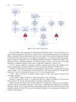
The procedure of experiment shown in Fig.10 is summarized as follows:
(1) Users apply for downloading the applet page through browser, and obtain the
corresponding class files for the laboratory platform according to the response event
on the page from the Server. Then the virtual machine in the client is run to initialize
the window of the user interface.
(2) According to the experiment demand, users choose experiment device com-
ponents including two Generators, one Adder, one FIRLowFilter and two Oscillo-
scopes in the left equipment list in the interface.
(3) Users add these device components into the experiment panel, and can mod-
ify the component attributes from the attribute list-box in the right in terms of their
own demands. Then all components in the experiment panel are connected according
to the experiment flow, which is shown in Fig.10.
(4) Users push the “run” button. The client checks the device components in the
queue automatically, and organizes these components in terms of the experiment
flow.
(5) According to the preset attributes in the component, two Generators generate
32 bytes signal data respectively, and send them to the Adder. The Adder component
makes the two 32 bytes signal data overlapped and send the result to the FIRLowFilter
component and one Oscilloscope component respectively. The Oscilloscope component
displays the overlapped signal in the result panel. The FIRLowFilter component sends
the data stream to the server to invoke “fir1” function and “filter” function in Matlab.
The results of Matlab functions are sent back to the FIRLowFilter component. The