Getting Started with Open Office .org 3 part 22 potx
Bạn đang xem bản rút gọn của tài liệu. Xem và tải ngay bản đầy đủ của tài liệu tại đây (4.77 MB, 10 trang )
Icon Function
Snap to object borders
Snap to object points
Allow quick editing
Select text area only
Double-click to edit text
Simple handles
Large handles
Create object with attributes
Picture placeholders
Contour mode
Text placeholders
Line contour only
Exit all groups
Positioning objects with snap functions
In Draw, objects can be positioned to grid points, to special snap points
and lines, to object frames, to single object points, or to page edges.
This function is known as
Snap
. In this manner objects can be very
accurately positioned in a drawing.
If you want to use the snap function, it is much easier to work with the
highest practical zoom value. It is possible to use two different snap
functions at the same time, for example snap to a guide line and to the
page edge. It is best, however, to activate only those functions that you
really need.
This section describes the snap-to-grid function. For more information
about this and the other snap functions, see Chapter 8 (Tips and
Tricks) and Chapter 10 (Advanced Draw Techniques) in the
Draw
Guide
.
Chapter 7 Getting Started with Draw 211
Snap to grid
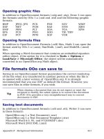
Use this function to move an object exactly to a grid point (see Figure
157). This function can be switched on and off with View > Grid >
Snap to Grid and on the Options toolbar with the icon .
Figure 157: With snap to grid,
objects align to the grid precisely.
Showing the grid
Make the grid visible under View > Grid > Display Grid.
Alternatively turn the grid on and off with the icon on the Options
toolbar.
Configuring the grid
The color, spacing, and resolution of the grid points can be individually
chosen for each axis.The spacing between the lines is defined in the
Grid options dialog under the Drawing area of the OOo options (Tools
> Options > OpenOffice.org Draw > Grid). In the dialog shown in
Figure 158, you can set the following parameters:
• Vertical and horizontal spacing of the dots in the grid. You can
also change the unit of measurement used in the general Draw
options (Tools > Options > OpenOffice.org Draw > General).
• The resolution is the size of the squares or rectangles in the grid.
If the resolution is Horizontal 1cm, Vertical 2cm, the grid consists
of rectangles 2cm high and 1cm wide.
• Subdivisions are additional points that appear along the sides of
each rectangle or square in the grid. Objects snap to subdivisions
as well as to the corners of the grid.
• The pixel (pix element) size of the snap area defines how close
you need to bring an object to a snap point or line before it will
snap to it.
212 Getting Started with OpenOffice.org 3
Figure 158. Setting grid options
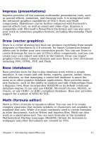
Changing the color of the grid points
The default grid dots are light gray, which can be hard to see. To
improve visibility, go to Tools > Options, then OpenOffice.org >
Appearance (Figure 159).
Figure 159: Changing the grid color
Chapter 7 Getting Started with Draw 213
In the
Drawing / Presentation
section, you can change the color of the
grid points. On the
Color Settings
pulldown menu, select a more
suitable/visible color, for example black.
Positioning objects with helper lines
To simplify the positioning of objects it is possible to make visible
guiding lines—extensions of the edges of the object—while it is being
moved. These guiding lines have no snap function.
The guiding lines can be (de-)activated under Tools > Options >
OpenOffice.org Draw > View > Guides when moving, or by
clicking on the icon on the
Options
toolbar.
The basic drawing shapes
Draw provides a wide range of shapes, located in palettes accessed
from the Drawing Toolbar. This chapter describes only a few of the
basic shapes; see the
Draw Guide
for a complete description of the
shapes available. These shapes include rectangles and squares; circles,
ellipses, and arcs; 3D objects; curves; lines and arrows; text; and
connectors.
When you draw a basic shape or select one for editing, the
Info
field in
the status bar changes to reflect the action taken:
Line created
,
Text
frame xxyy selected
, and so on.
Figure 160 shows part of the Drawing toolbar with the icons needed in
the following sections. The
Text
icon is also included.
Figure 160: Part of the Drawing
toolbar
Drawing a straight line
Let’s start by drawing the simplest of shapes: a straight line. Click on
the Line icon on the Drawing Toolbar and place the mouse pointer
where you want to start the line. Drag the mouse while keeping the
button pressed. Release the mouse button when you want to end the
line.
A blue or green selection handle appears at each end of the line,
showing that this is the currently selected object. The colors depend on
214 Getting Started with OpenOffice.org 3
the selection mode (green for simple selection and blue when in point
edit mode). This effect is easily apparent if on the Options toolbar both
Simple Handles and Large Handles are switched on.
Figure 161: Drawing a straight line
Hold down the
Shift
key while drawing the line to restrict the angle of
the line to a multiple of 45 degrees (0, 45, 90, 135, and so on.
Hold down the
Control
key (
Ctrl
in PCs) to snap the end of the line to
the nearest grid point.
Note
The effect of the
Ctrl
key depends on the settings of the Snap to
Grid option on the View->Grid menu:
Snap to Grid on:
Ctrl
deactivates the snap option for this
activity.
Snap to Grid off:
Ctrl
activates the snap option for this activity.
The spacing (resolution) of the grid points can be adjusted under Tools
> Options > OpenOffice.org-Draw > Grid. See also Chapter 8 (Tips
and Tricks) in the
Draw Guide
.
Hold down the
Alt
key to extend the line symmetrically outward from
the start point (the line extends to each side of the start point equally).
This lets you draw straight lines by starting from the middle of the line.
The line just drawn has all the default attributes, such as color and line
type. To change the line attributes, click on the line to select it and
then use the tools in the Line and Filling toolbar; or for more control,
right-click on the line and choose Line to open the Line dialog.
Drawing an arrow
Arrows are drawn like lines. Draw classifies arrows as a subgroup of
lines: Lines with arrowheads. They are shown in the information field
on the status bar only as lines. Click on the Line Ends with Arrow
icon to draw an arrow.
Chapter 7 Getting Started with Draw 215
Drawing lines and arrows
Click on the small black triangle on the Lines and Arrows icon to
open a floating toolbar with ten tools for drawing lines and arrows
(Figure 162). Alternatively, you can click directly on the symbol to
repeat the last-used command chosen from this toolbar. In both cases,
the last-used command will be stored on the toolbar to make it quicker
to call it up again.
Figure 162: Lines and Arrows toolbar
Drawing a rectangle or square
Drawing rectangles is similar to drawing straight lines, except that you
use the Rectangle icon from the Drawing Toolbar. The (imaginary)
line drawn with the mouse corresponds to the diagonal of the
rectangle. In addition, the outline of the future rectangle changes
shape as you drag the mouse around. The outline is shown as a dashed
line until you release the mouse button, when the rectangle is drawn.
Figure 163: Drawing a rectangle
Hold down the
Shift
key to draw a square. Hold down the
Alt
key to
draw a rectangle starting from its center. To combine the effects, hold
down both the
Shift
and
Alt
keys simultaneously.
216 Getting Started with OpenOffice.org 3
Starting point
Drawing a circle or ellipse
To draw an ellipse (also called an oval) or a circle, use the Ellipse icon
from the Drawing Toolbar. (A circle is simply an ellipse where the
two axes are the same length.) The ellipse drawn is the largest ellipse
that would fit inside the (imaginary) rectangle drawn with the mouse.
Figure 164: Drawing an ellipse
There are three other ways to draw an ellipse or circle:
• Hold down the
Shift
key while drawing to force the ellipse to be a
circle.
• Hold down the
Alt
key to draw a symmetrical ellipse or circle
from the center instead of dragging corner to corner.
• Hold down the
Control
key while drawing to snap the ellipse or
circle to grid lines.
Note
If you first press and hold the
Control
key and then click on one
of the icons (Line, Rectangle, Ellipse, or Text), an object is
drawn automatically in the work area—the size, shape, and
color are all standard values. These attributes can be changed
later, if desired.
Drawing curves
The tools for drawing curves or polygons are on the toolbar that
appears when you click the Curve icon on the Drawing toolbar.
This toolbar contains eight tools (Figure 165).
Note
Hovering the mouse over this icon gives a tooltip of
Curve
. If
you convert the icon to a floating toolbar, however, the title is
Lines
, as shown in Figure 165.
Chapter 7 Getting Started with Draw 217
Starting point
Figure 165: Floating Curves toolbar (incorrectly titled “Lines”)
If you move the mouse cursor over one of the icons, a tooltip pops up
with a description of the function. For a more detailed description of
the handling of Bézier curves (curves and filled curves), see Chapter
10 (Advanced Draw Techniques) in the
Draw Guide
.
Polygons
Draw the first line from the start point with the left mouse button
held down. As soon as you release the mouse button, a first corner
point is drawn, and you can move the mouse to see how the second
line will look. Every mouse click sets another corner point. A double-
click ends the drawing. A filled polygon automatically joins the last
point to the first point to close off the figure and fills it with the
current standard fill color. A polygon without filling will not be
closed at the end of the drawing.
Polygon 45°
Just as with ordinary polygons, these will be formed from lines but
with angles of 45 or 90 degrees between them.
Freeform Line
With this tool you can draw just like with a pencil. Press and hold
the left mouse button and move the mouse. It is not necessary to end
the drawing with a double-click. Just release the mouse button and
the drawing is completed. If you have selected
Freeform Line, Filled
,
the end point is joined automatically to the start point and the object
is filled with the appropriate color.
Writing text
Use the Text tool to write text and select the font, color, size, and
other attributes. Click on an empty space in the workspace to write the
text at that spot or drag an area to write inside the dragged frame.
Press
Enter
to drop to the next line.
When you have finished typing text, click outside the text frame.
Double-click on the text at any time to edit it.
218 Getting Started with OpenOffice.org 3
Freeform Line, Filled
Polygon, Filled
Curve, Filled
Freeform Line
Polygon (45°), Filled
Polygon (45°)Polygon
Curve
When you type text, the upper toolbar includes the usual paragraph
attributes: indents, first line, and tab stops.
You can change the style of all or part of the text. The Styles and
Formatting window also works here (select Format > Styles and
Formatting or press
F11
to launch), so you can create Graphics styles
that you can reuse for other text frames. Graphics styles affect all of
the text within a text frame. To style parts of the text, use direct
formating with the toolbar.
Text frames can also have fill colors, shadows, and other attributes,
just like any other Draw object. You can rotate the frame and write the
text at any angle. These options are available by right-clicking on the
object.
Use the Callout tool, located on the Drawing toolbar, to create callouts
(also known as captions or figure labels).
If you double-click on an object or press
F2
(or the Text icon in the
Drawing toolbar) when an object is selected, text is written in the
center of the object and remains within the object. Nearly any kind of
object contains such an additional text element. These texts have slight
differences to those in text frames concerning position and
hyphenation.
For more about text, see Chapter 2 (Drawing Basic Shapes) and
Chapter 10 (Advanced Draw Techniques) in the
Draw Guide
.
Gluepoints and connectors
All Draw objects have associated invisible
gluepoints
. Most objects
have four gluepoints, as shown in Figure 166.
Figure 166: Four gluepoints
Gluepoints are different from handles (the small blue or green squares
around an object). Use the handles to move or resize an object; use the
gluepoints to attach connectors to an object.
You can add more gluepoints, and customize gluepoints, using the
toolbar of the same name. Gluepoints become visible when you click
Chapter 7 Getting Started with Draw 219
the Gluepoints icon on the Drawing toolbar and then move the end
of a connector over the object.
Connectors
are a type of line or arrow whose ends dock to glue points
on other objects. When you move the other object, the connector
moves with it. Connectors are particularly useful for making
organizational charts. You can reorganize the blocks of your chart and
all the connected objects stay connected.
Figure 167 shows two Draw objects and a connector.
Figure 167: A connector between two objects
Draw has a range of advanced connector functions. You can change
connector types using the context menu or by opening the floating
Connectors toolbar (click on the Connector icon ). For more about
connectors and gluepoints, see Chapter 9 (Organization Charts, Flow
Diagrams, and More) in the
Draw Guide
.
Drawing geometric shapes
Geometric shapes include basic shapes, symbol shapes, block arrows,
flowcharts, callouts, and stars.
Figure 168 shows part of the Drawing toolbar with the icons necessary
for the following sections. They open floating toolbars with the relevant
work tools. The use of all these tools is similar to that of the Rectangle
tool, even though they produce different geometric shapes.
Figure 168: Part of the main Drawing toolbar
220 Getting Started with OpenOffice.org 3