Resource Management in Satellite Networks part 6 pps
Bạn đang xem bản rút gọn của tài liệu. Xem và tải ngay bản đầy đủ của tài liệu tại đây (348.1 KB, 10 trang )
Chapter 1: INTRODUCTION TO SATELLITE COMMUNICATIONS 27
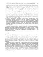
Fig. 1.8: The four possible DVB-S2 constellations before physical layer scrambling.
1.4.5 Numerical details on the selected scenarios for performance
evaluations
This sub-Section provides some basic characteristics and numeric values for
the parameters that have been used when evaluating the performance of the
techniques proposed in the following Chapters of this book for the different
scenarios. The details are provided below.
Scenario 1: S-UMTS as well as S-HSDPA
• GEO satellite
• Multi-spot-beam satellite antenna
• Bent-pipe satellite
• Terrestrial gateway containing the scheduler (MAC layer)
• Direct return link via satellite for channel quality measurements in case of
point-to-point services
• Mobile users (mean speed equal to 60 km/h)
• GOOD-BAD Markov channel model (typically, 6 s mean GOOD duration
and 2 s mean BAD duration) [29]
• IP-based traffic flows with UMTS transport layer encapsulation
• Traffic sources: video sources (sum of ON/OFF Markovian sources) [30]
and Web sources (2-MMPP arrival process of Pareto-distributed data-
grams) [31].
28 Giovanni Giambene
Scenario 2: DVB-S/DVB-RCS
• GEO satellite
• Single beam or multi-spot-beam satellite antenna
• Bent-pipe satellite
• Architecture involving an NCC and at least a GW
• Fixed users
• Direct return link for channel quality measurements; typically, Ka band is
used (maximum capacity 2 Mbit/s)
• Forward link in K band
• Channel model: only troposphere effects (rain scintillation and gas) have
to be considered. Basically an Additive White Gaussian Noise (AWGN)
model has been adopted with a given packet error rate (uncorrelated losses)
• IP-based traffic flows with MPE encapsulation and generation of packets
according to the MPEG2-TS format
• Traffic sources of the FTP type (elephant TCP connections).
Scenario 3: LEO constellation
• A Teledesic-like LEO system (the Boeing design with 288 satellites):
altitude of 1375 km, and satellite capacity of 32 Mbit/s
• Multi-spot-beam satellite antenna
• End-users must switch from spot-beam to spot-beam and from satellite to
satellite, resulting in frequent intra- and inter-satellite handovers
• We assume a two-dimensional mobility model: users move in straight lines
and at constant speed (satellite ground track speed composed with the
Earth rotation speed)
• All the spot-beam footprints are identical in shape and size (approximated
by rectangles, 1790 km × 1790 km)
• Traffic assumptions (study made in Chapter 8, Section 8.6): non-real-time
traffic for email or FTP and real-time multimedia traffic, e.g., interactive
voice and video applications. For each class: (i) new calls arrive in the foot-
prints according to independent Poisson processes; (ii) call holding times
are exponentially distributed. Within each traffic class, three different user
types are considered that are differentiated depending on the call holding
time and bit-rates.
1.5 Satellite networks
A satellite network can play several roles [32]. In particular, it can be used as
Access Network for final users or it can be part of the Core Network. Some
examples are shown in Figure 1.9.
The ETSI TC-SES/BSM (Satellite Earth Stations and Systems / Broad-
band Satellite Multimedia) working group had the task to focus on IP layer
Chapter 1: INTRODUCTION TO SATELLITE COMMUNICATIONS 29
Fig. 1.9: Examples for the use of satellite links in telecommunication networks.
interworking, to define a new network architecture and to include alternative
families of lower layer air interfaces [33]. A Broadband Satellite Multimedia
(BSM) network is divided into 5 domains, as specified in ETSI TR 101 984
[32]:
• User Domain, representing the group of end-users;
• Access Domain that denotes the access network that is used to connect to
the service provider (e.g., ADSL, UMTS, satellite);
• Distribution Network : this is an intermediate network that is interposed
between the access network and the core network;
• Core Network, representing the backbone transport network that is used
to connect the routers on a geographical area;
• Content Domain that represents the area where contents and information
are stored to be made available to users.
The user requesting contents should access them feeling like as he/she was
directly connected to the source of the information, the Content Domain;
practically, many domains are traversed that are transparent to the user.
Let us now consider the BSM network functions from the protocol stack
standpoint (see Figure 1.10) that can involve different layers, as specified in
ETSI TR 101 985 [34]:
• The BSM network operates at layer 2, like a bridge.
• The BSM network operates at layer 3, so that the satellite Earth stations
are routers.
• The BSM network operates at a layer above the 3
rd
one: the satellite
Earth stations are gateways. In this case, these stations can perform a
more accurate routing based not only on the IP datagram header, but also
on information of higher layer headers. In such a case, the Earth station can
implement special functions, like Performance Enhancing Proxies (PEPs)
30 Giovanni Giambene
that are important in order to improve the TCP performance in satellite
networks.
Fig. 1.10: BSM general network architecture.
Very Small Aperture Terminal (VSAT) networks are a special case of BSM
networks where the user terminal employs a small antenna (i.e., VSAT) and
simplified equipment so as to reduce costs. This small satellite terminal can
be used for one way and/or interactive communications. VSATs can support
several applications, such as: satellite news gathering, supervisory control
and data acquisition, inquiry/response, TV and audio broadcasting, data
distribution. VSAT networks are based on GEO satellites (typically of the
bent-pipe type) according to a star topology: an Earth station acts as a hub
(= gateway to the terrestrial network and master control station), receiving
and transmitting all the data fluxes from/to VSATs. The forward link (from
the hub to VSATs) is via GEO satellite. The return link (from VSAT to the
hub) is typically via a terrestrial Public Switched Telephone Network (PSTN)
link (to simplify the antenna design on the VSAT). Hence, forward and return
links have an asymmetrical capacity; anyway recent advances in this field also
allow the return link via satellite. Referring to the network architecture in
Figure 1.10, the VSAT includes the client and the Earth station on the left;
whereas, the hub coincides with the Earth station on the right. Different
VSAT platforms use various technologies in order to access the satellite radio
space segment and to share it among multiple users. One of the problems
that VSAT networks have faced during their evolution has been the lack of
compliance to any specific standards. In the last years, standardization bodies
have established new standards to support satellite Internet [23]. The DVB
standard has been the first one to be published, and ETSI adopted DVB-RCS
for satellite return link transmissions. Another standard is IPoS (Internet
Protocol over Satellite) developed by HNS (Hughes Network Systems)and
Chapter 1: INTRODUCTION TO SATELLITE COMMUNICATIONS 31
standardized by ETSI. Finally, DOCSIS-S (Data Over Cable Service Interface
Specification for Satellite), a modification to the DOCSIS cable-modem has
been proposed for adapting it to the transmissions over satellite.
Let us focus on satellite IP networks. The ETSI TC-SES/BSM working
group has defined the protocol stack architecture shown in Figure 1.11 where
lower layers depend on satellite system implementation (Satellite-Dependent,
SD, layers) and higher layers are those typical of the Internet protocol stack
(Satellite-Independent, SI, layers). These two blocks of stacked protocols are
interconnected through the SI-SAP (Satellite-Independent - Service Access
Point) interface. Only a small number of generic functions need to cross the
SI-SAP; in particular: address resolution, resource management, traffic classes
QoS.
The SI-SAP interface is logically divided into three SAPs, each of them
with a suitable function and security characteristics, as described in the ETSI
TS 102 465 standard [35]. In particular, we have:
• SI-U-SAP (User-SAP): transfer of IP packets between the users;
• SI-C-SAP (Control-SAP ): transfer of control data and of service signaling
for SI-U-SAP;
• SI-M-SAP (Management-SAP): transfer of management information.
The protocol stack organization defined by TC-SES/BSM (see Figure 1.11)
has been taken as the basis for the organization of the work in this book, where
after a first part with introductory concepts, the second part deals with SD
layers and the third part focuses on SI protocol layers. More details on the
BSM protocol stack are provided in the following sub-Section.
1.5.1 SI-SAP interface overview
SI-SAP defines an interface between SI upper layers and SD lower layers,
that applies to all air interface families for satellite communication systems
[32],[34]. SI-SAPs correspond to the endpoints of BSM bearer services. SI-SAP
is used to define standard SI bearer services that are built upon lower
layer transmission services. Point-to-point, point-to-multipoint, multipoint-
to-multipoint and broadcast bearer services are defined as the edge-to-edge
services provided by the BSM sub-network. SI-SAP provides an abstract
interface allowing BSM protocols (BSM address resolution, BSM resource
management, etc.) to perform over any BSM family (i.e., layer 1 and 2
technology) [33]. For traffic handling purposes, SI-SAP uses a BSM Identifier
(BSM
ID) and Queuing Identifiers (QIDs):
• The BSM
ID uniquely identifies a BSM network point of attachment
and allows IP layer address resolution protocols (equivalent to Address
Resolution Protocol,ARPforIPv4andNeighbor Discovery,NDforIPv6)
to be used over the BSM.
32 Giovanni Giambene
Fig. 1.11: Standardized protocol stack.
• QIDs are abstract queues (SI-SAP level) that represent the layer 2 queues
in a general way to allow the mapping with layer 3 ones (note that
using a QoS support mechanism at layer 3, different queues are needed).
QIDs are a way to hide specific SD layer implementations (i.e., BSM
technology) from the IP layer. Each QID queue is characterized by
QoS-specific parameters (flowspecs, path label or Differentiated Service,
DiffServ, marking) and is associated to lower layer transfer capabilities
(i.e., capacity allocation methods) and buffer management policies [36].
The SD layers are responsible for assigning satellite capacity to these
abstract queues (e.g., in DVB-RCS we can consider the allocation methods
such as CRA, VBDC, etc., and combinations of them). The mapping of
IP queues to QIDs is flexible: there is no strict constraint for a one-to-one
mapping, but we may also consider that more IP queues correspond to the
same QID (in this case, a scheduler should be used at layer 3 to determine
the service order of the different queues to be mapped to the same QID).
BSM networks use a suitable and general categorization of traffic flows
in traffic classes that can be mapped to classical IP QoS classes [25]. In
particular, 8 traffic classes, i.e., service priority levels, are defined from 0
for emergency services to 7 for low priority broadcast/multicast traffic.
Other functional blocks are involved in the management of the queues in
BSM protocol architecture; the interested reader may refer to [36].
All the BSM services (data transfer, address management, group adver-
Chapter 1: INTRODUCTION TO SATELLITE COMMUNICATIONS 33
tisement, etc.) use SI-SAP primitives [37]. These primitives are classified
into functional groups within the User plane (U), Control plane (C) and
Management plane (M). The primitives (exchanged between the upper layers
and the lower layers) are of the following four types:
• The REQUEST primitive
type is used when the SI layer is requesting a
service from the SD layer.
• The INDICATION primitive
type is used by the SD layer to notify the SI
layer of activities. This type may either be related to a REQUEST type
at the peer entity, or may be an indication of an unsolicited lower layer
event.
• The RESPONSE primitive
type is used by the SI layer to acknowledge the
receipt of the INDICATION type from the SD layer.
• The CONFIRM primitive
type is used by the SD layer to confirm that the
activity requested by a previous REQUEST primitive has been completed.
The services provided at the SI-SAP level are divided into functional
groups for U-, C-, and M-plane, as described below [37]. Each service uses
one or more different types of the above-mentioned primitives.
• U-plane services
– Data Transfer: These services are used to send and receive user data
via the SI-SAP. Data transfer services can be used for both unicast and
multicast data transfer.
• C-plane services
– Address Resolution: A mechanism to associate a BSM
ID address to a
given IPv4 unicast or multicast address. A successful address resolution
service returns the associated BSM
ID. The BSM ID can be either a
Unicast ID for unicast services or a Group ID for multicast services.
– Resource Reservation: These services are used to open, modify and
close SD layer queues (for both unicast and multicast flows) to be used
by SI layers. This function assigns the QID and defines or modifies
the properties of the abstract queue that is associated with that QID.
Resource reservation is required only for sending data (not for receiving
data).
– Group Receive/Send: They are mechanisms to activate and configure
the SD layers to receive/send a needed multicast service. These services
are used to associate a multicast group address (e.g., an IPv4 Class D
address, or an IPv6 multicast address) with a series of SD parameters.
– Flow Control: These primitives allow activating and adjusting the SD
layers to provide SI-SAP flow control for a specific QID (i.e., on one or
more of the SD layer queues).
• M-plane services
– At present, no M-plane services are defined in the standard.
34 Giovanni Giambene
1.6 Novel approaches for satellite networks
The increasing demand for multimedia broadband services and high-speed
Internet access via satellite requires the definition of an optimized satellite
protocol stack as well as the full integration of the satellite network with
terrestrial ones. Consequently, two innovative approaches are at present
conceived [38], namely horizontal approach and vertical approach.
1.6.1 Horizontal approach
We expect that different wireless technologies (e.g., wireless local area net-
works, cellular systems, satellite networks) need to co-operate to allow the
best radio coverage to the users, depending on their locations, mobility
characteristics, applications, user profile, etc. This is in accordance with the
Always Best Connected (ABC) paradigm. Therefore, it is necessary that the
use of the resources in the different Radio Access Networks (RANs) be globally
coordinated by means of a resource brokerage function. Such intelligence is
centralized and allocates sessions to RANs or switches them from one to
another, when some conditions are meet.
1.6.2 Vertical approach
The ISO/OSI reference model and the Internet protocol suite are based on
a layering paradigm. Each protocol solves a specific problem by using the
services provided by modules below it and gives a new service to upper layers.
The disadvantages of such approach can be detailed as follows:
• The needs of a service provided by the communication system to its users
are defined at the top-level, but the hierarchy and the overall system
performance are built upon the bottom-level.
• The bottom level does not communicate directly, but through intermediate
layers with the top-level. Information is lost during this layer-by-layer top-
down conversion.
• Layers are independently optimized. However, in many cases, the close
interaction among them should be considered.
A strict modularity and layer independence may lead to non-optimal
performance in IP-based next-generation satellite communication systems.
Finally, since both radio and power resources are strongly constrained on the
satellite, a protocol optimization is mandatory. Such optimization requires a
vertical design of the air interface protocol stack. Such cross-layer approach
entails new interfaces across the layers, which exchange control information
beyond the standard ISO/OSI structure. Cross-layer interfaces can be between
or beyond adjacent protocol layers. Although interfaces between adjacent
layers are in general preferable, there can be the need for efficient and direct in-
teractions between non-adjacent layers [39]; in general, a layer should be aware
Chapter 1: INTRODUCTION TO SATELLITE COMMUNICATIONS 35
of the internal state of the other layers of the protocol stack. For instance,
OSI layer 3 (e.g., IP) and above often need direct interfaces to OSI layer 2,
e.g., for handover support. Another example concerns transmission parameters
(e.g., transmission mode, channel coding and persistency degree for link layer
retransmissions) that must be related to application characteristics (e.g., type
of information, source coding, etc.), network characteristics, user preferences
and context of use. Finally, lower layers (i.e., 1 and 2) should be aware of
higher layer (i.e., 3 and 4) behaviors in order to take appropriate decisions on
traffic management.
Cross-layer methods can be classified into two broad groups as follows:
• Implicit cross-layer design: there is no exchange of signaling among differ-
ent layers during operation, but in the design phase cross-layer interactions
are taken into consideration for a joint optimization.
• Explicit cross-layer design: signaling interactions among (non-)adjacent
protocol levels are employed so that the internal state of a protocol can be
made available to the protocols at different layers for dynamic adaptations.
The above distinction of methods is at the basis of all the different
cross-layer schemes presented in the following Chapters of this book.
As for explicit cross-layer methods, new interfaces are needed beyond adja-
cent layers. Different solutions have been proposed to support the cross-layer
exchange of signaling information; an interesting method has emerged from
the following papers [40]-[43], where a ‘global coordinator’ of the different
layers is considered allowing to acquire status information from the different
protocols to store it in a shared memory and to set the internal state of the
protocols to be adaptable to different events. A possible implementation of
the global coordinator could be to exploit the capabilities of the management
plane of the protocol stack that can interact and coordinate the different
layers. The management plane could exploit the control service access points
between layers to send control broadcast signaling to all the layers for their
respective actions. More details on these aspects are provided in Chapter 4.
Finally, referring to the ETSI TC-SES/BSM protocol stack architecture
shown in Figure 1.11, it is important to note here that the cross-layer methods
involving SD and SI layers will require the adoption of suitable primitives
crossing the SI-SAP interface. In order to explain BSM cross-layer interactions
and their relations to SI-SAP, some examples are proposed below for both
implicit and explicit cross-layer design cases.
BSM Protocol Manager
The BSM Protocol Manager (BPM) has been conceived in the BSM protocol
stack to maintain QoS and evaluate the BSM performance [44]. BPM resides
above the SI-SAP and defines how IP protocols and packet markings are
interpreted and transmitted through the BSM, which SI protocols are used
36 Giovanni Giambene
and how they in turn trigger the SD functions (see Figure 1.12). BPM
has interfaces at different levels of the BSM protocol stack. In particular,
BPM interacts with a specific middleware to establish transport level and
application level PEPs, communicates with bandwidth brokers and potentially
with service discovery and security/authentication functions. BPM directly
interacts with IP protocols, including Multiprotocol Label Switching (MPLS)
for route discovery and Integrated Service (IntServ) or Differentiated Service
(DiffServ) models (see Chapter 8, Section 8.2, for more details). For all these
reasons the BPM could represent a viable solution to implement the so-called
‘global coordinator’ (explicit cross-layer approach design). In such a case
suitable primitives should be designed to support cross-layer signaling through
the C-plane.
Fig. 1.12: Protocol manager and BSM protocol architecture [44].
Implicit cross-layer design examples
An example of implicit cross-layer (i.e., joint protocol design/optimization)
could be PHY layer adaptation in the presence of ACM with thresholds
between modes that have been selected to optimize the transport layer
performance [39].
Explicit cross-layer design examples
It is possible to distinguish between explicit cross-layer involving layers across
SI-SAP or involving layers in SD or SI.