Advances in Satellite Communications Part 6 ppt
Bạn đang xem bản rút gọn của tài liệu. Xem và tải ngay bản đầy đủ của tài liệu tại đây (554.37 KB, 15 trang )
Advances in Satellite Communications
64
VJHC scheme stated that TCP/IP header fields can be grouped into several categories,
which are constant, inferred and dynamic (Jacobson, 1990). Constant fields are those field
values that remained unchanged between consecutive packets, hence, can be eliminated.
Inferred fields are those fields that can be recalculated at the receiving end. For example,
‘total length’ and ‘header checksum’ field. The transmission efficiency can be improved
significantly by suppressing inferred fields at the compressor and restoring them at the
decompressor. The third group is dynamic fields which do no change frequently at the same
time or change slightly, thus it can be omitted in most cases.
VJHC is proven to be effective towards header compression, as it can reduce TCP/IPv4
header from 40B to 4B, which is 10% of its original size (Tye & Fairhurst, 2003). However,
the main disadvantage of VJHC scheme is it may lead to error propagation throughout the
transmission when a compressed packet is lost on the link. This is due to the inconsistent
context which will cause a series of packets to be discarded at the receiver end. Thus, VJHC
scheme is not applicable under satellite link with high bit error rate as this will lead to
higher packet drop which will cause the satellite link performance to become even worse.
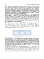
4.2.1.2 RObust Header Compression (ROHC)
Besides VJHC, RObust Header Compression (ROHC) scheme is another well known header
compression scheme. It is developed by ROHC working group of the IEFT (Tye & Fairhurst,
2003). ROHC is used for compressing IP packet headers and it is particularly suitable for
wireless network. ROHC scheme allows bandwidth savings up to 60% in VOIP and
multimedia communication applications (JCP-Consult, 2008). In this scheme, compression
and decompression are treated as a series of states.
Fig. 8. Compressor state diagram (Effnet, 2004).
As shown in Figure 8, ROHC compressor operates in 3 states, which are Initialization and
Refresh (IR), First Order (FO) and Second Order (SO) (Effnet, 2004). The concept of flow
context is also adopted in this scheme. The states describe the increasing level of confidence
about the correctness of the context at the decompressor side. This confidence is reflected in
the increasing compression of packet headers. Initially, the compressor will start with the
lowest state and gradually moving to higher state. When there is any error occurred, which
will be indicated in the feedback packets, the compressor will move to a lower state to
resend packets to fix the error.
Similar to the compressor, ROHC decompressor also operates in 3 states, namely No
Context, Static Context and Full Context as illustrated in Figure 9 below (Effnet, 2004). In the
beginning of the packet flow, the decompressor will start in the first state, No Context as it
has no context information available yet. Once the context information is created at the
decompressor site, the decompressor will move to higher state, Full Context state. In the
case of error condition, the decompressor will move to lower state to fix the error.
Improving Quality-of-Service of Real-Time Applications over
Bandwidth Limited Satellite Communication Networks via Compression
65
Fig. 9. Decompressor state diagram (Effnet, 2004).
The major advantages of ROHC over VJHC are improved efficiency and high robustness.
ROHC works well over links with high bit error rates and long round trip times such as
cellular and satellite network. Moreover, its framework is extensible and it is designed to
discover dependencies in packets from the same packet flow. However, ROHC scheme is
very complicated to be implemented as it absorbed all the existing compression techniques.
In addition, in ROHC scheme, the decompressor needs to generate feedback packet and
send it back to the compressor to acknowledge successful decompression. Besides that, the
context updating information is also sent periodically to ensure context synchronization.
This will easily lead to network congestion when working under a low bandwidth satellite
link with heavy traffic flows as ROHC scheme increases the network load by generating
feedback and context information packets from time to time.
4.3 Payload compression
Packet payload is used to store user information and bulk compression method is usually
used for compressing packet payload. Bulk compression treats information in the packets as
a block of information and compresses it using a compression algorithm (Tye & Fairhurst,
2003). The compressor will construct a dictionary for the common sequences found within
the information and then match each sequence to a shorter compressed representation or a
key code.
Two types of dictionary, namely a running dictionary which based on the compression
algorithm used or a pre-defined dictionary that can be used for bulk compression. In bulk
compression, the decompressor must use an identical dictionary which is used during
compression and bulk compression is known to achieve higher compression ratio. However,
the data dictionary requires larger memory allocation and the dictionaries at both the
compressor and decompressor sides have to be fully synchronized.
4.3.1 Payload compression schemes
Apart from packet and header compression, two payload compression schemes have been
proposed by other researchers, which are Adaptive Compression Environment (ACE)
system and Adaptive Online Compression (AdOC) algorithm.
Advances in Satellite Communications
66
4.3.1.1 Adaptive Compression Environment (ACE)
Adaptive Compression Environment (ACE) intercepts program communication and applies
on-the-fly compression (Krintz & Sucu, 2006). On-the-fly or online compression is
mandatory for those real-time interactive applications. ACE is able to adapt to the changes
in resource performance and network technology, thus the benefits from using ACE become
apparent when the underlying communication performance varies or the network
technology changes as in mobile communication network. ACE employs an efficient and
accurate forecasting toolkit, which is known as Network Weather Service (NWS) to predict
and determine whether applying compression will be profitable based on underlying
resource performance.
Short-term forecasts of compression ratio, compressed and uncompressed transfer time is
made by NWS using a series of estimation techniques, together with its own internal models
that estimate compression performance and changes in data compressibility.After that,
based on the end-to-end path information obtained by NWS, ACE will select between
several widely used compression techniques, which include bzip, zlib and LZO to perform
the transparent compression at TCP socket level. ACE compresses data in 32KB blocks and a
4-byte header is appended to each block to indicate the block size and compression
technique used. It is proven to improve transfer performance by 8-93 percent over
commonly used compression algorithm (Krintz & Sucu, 2006).
However, ACE may introduce computation overheads due to massive amount of
computation are needed during the prediction process. Besides, problem like prediction
error which will lead to inaccurate decision may occur and large compression time cost of
the compression algorithm such as bzip may impose additional delays. Thus, ACE may not
be suitable and may impose additional delays over satellite network.
4.3.1.2 Adaptive Online Compression (AdOC)
This work proposed a general purpose portable application layer compression algorithm
known as AdOC. AdOC is an adaptive online compression algorithm suited for any
application data transfer and it automatically adapts the level of compression to the speed of
the network (Jeannot et al., 2002). Multithreading and First-In-First-Out (FIFO) data buffer
are two important features of this algorithm.
In this algorithm, the sender consists of two threads, namely compression thread and
communication thread. Compression thread is used to read and compress the data, while
communication thread is responsible to send the data. A FIFO data buffer is created to
store the data prior to transmission. The compression thread will write the data into the
FIFO data buffer, while the communication thread will retrieve the data from it. Thus, the
compression level used in the process of compression is depending on the size of the FIFO
queue.
To completely eliminate the overhead encountered when data cannot be compressed, AdOC
algorithm compresses data into smaller and independent chunks. This made AdOC less
reactive to short term changes in bandwidth, but keeping the same compression level for
long runs of data also improves the compression ratio (Jeannot et al., 2002). However, too
small chunks of data will simply caused overhead of FIFO queue, hence, the size of data
chunks need to be determined appropriately. Since AdOC algorithm compresses data into
smaller and independent chunks, network load may be increased and network congestion
may occur when works under satellite network.
Improving Quality-of-Service of Real-Time Applications over
Bandwidth Limited Satellite Communication Networks via Compression
67
5. Proposed real-time adaptive packet compression scheme
An overview of the proposed real-time adaptive packet compression scheme, with the
highlighting of its main concept and properties, is provided in this section. The block
diagram of the proposed compression scheme, together with the explanation of each stage
involved is also presented.
5.1 Concept of the proposed scheme
Concept of the proposed real-time adaptive packet compression scheme in satellite network
topology is shown in Figure 10 below. As stated earlier, the main objective of this research
study is to overcome the limitation and constraints of satellite communication link, which
are high latency and low bandwidth, therefore the performance of the satellite link has
become the main consideration in the proposed scheme. The proposed approach will focus
only on the high latency satellite link area, where the proposed scheme will be implemented
in both gateway A and gateway B. Both gateways will act as either compressor or
decompressor as the communication channel between gateway A and gateway B is a duplex
link.
In the proposed compression scheme, the concept of virtual channel is adopted to increase
network performance and reliability, simplify network architecture, and also improve
network services. Virtual channel is a channel designation which differs from the actual
communication channel and it is a dedicated path designed specifically for both sender and
receiver only. Since packet header compression is employed in the proposed scheme, thus
this concept is mandatory to facilitate data transmission over the link. The duplex link
between gateway A and gateway B in Figure 10 will act as the virtual channel, where the
rules of data transmission and the data format used are agreed by both gateways.
Fig. 10. Concept of the proposed compression scheme.
The flow of data transmission between both gateways is as discussed in the following. When
the transmitted data packets arrive at gateway A, the packets will undergo compression
prior to transmission over the virtual channel. When the compressed data packets reach
Advances in Satellite Communications
68
gateway B, the compressed packets will first undergo decompression before being
transmitted to the end user.
Apart from that, adaptive packet compression is mandatory due to the adoption of block
compression in the proposed scheme. Although block compression helps to increase the
compression ratio, however, it has its downside too. Block compression might impose
additional delay when the compression buffer is filled in a slow rate due to lack of network
traffic and a fast response is needed. This will further reduce the user experience of VSAT
satellite network. Therefore, to avoid this, packet blocks are compressed adaptively when
any of the predefined conditions is reached, which will be discussed in details in the
following section.
5.2 Strength of the proposed scheme
The proposed real-time adaptive packet compression scheme has several important
properties as discussed in the following. Firstly, the proposed scheme is accommodating all
incoming packets. To fully exploit the positive effect of compression, the proposed scheme is
not restricted to specific packet flow only but is applied to all incoming packets from
numerous source hosts and sites. One unique feature of the proposed scheme is the
adoption of virtual channel concept, which has not been used in other reviewed schemes.
This concept simplifies packet routing and makes data transmission more efficient,
especially when packet compression is employed. In the proposed scheme, to facilitate
packet transmission over the communication channel, a peer-to-peer synchronized virtual
channel is established between the sender (compressor) and receiver (decompressor).
Moreover, another important feature, block compression approach is also introduced. Block
compression exploits similarities of consecutive packets in the flow and compression is
performed on an aggregated set of packets (a block) to further improve the compression
ratio and increase the effective bandwidth.
Apart from that, both packet header and payload are being compressed in the proposed
scheme. In many services and applications such as Voice over IP, interactive games and
messaging, the payload of the packets is almost of the same size or even smaller than the
header (Effnet, 2004). Since the header fields remain almost constant between consecutive
packets of the same packet stream, therefore it is possible to compress those headers,
providing more than 90% (Effnet, 2004) saving in many cases. This helps to save bandwidth
and the expensive resources can be used efficiently. In addition to header compression,
payload compression also introduces significant benefit in increasing the effective
bandwidth. Payload compression compresses the data portion of the transmission and it
uses compression algorithms to identify relatively short byte sequences that are repeated
frequently over time. Payload compression provides a significant saving in overall packet
size especially for packets with large data portions.
In addition, adaptive compression is employed in the proposed scheme. Network packets
are compressed adaptively and selectively in the proposed scheme to exploit the positive
effect of block compression while avoiding the negative effect. To avoid greater delay
imposed by block compression, the set of aggregated packets (block of packets) in the
compression buffer is compressed adaptively based on certain conditions. If either one of
the conditions is fulfilled, the compression buffer is compressed. Else, the compression
buffer will not be compressed. By combining all the features listed above, the performance
of the proposed scheme will be greatly improved over other reviewed schemes.
Improving Quality-of-Service of Real-Time Applications over
Bandwidth Limited Satellite Communication Networks via Compression
69
5.3 Overview of the proposed scheme
Figure 11 below demonstrates the main components of the proposed real-time adaptive
packet compression scheme. The compression scheme made up of a source node (Gateway
A) which acts as the compressor and a destination node (Gateway B) which is the
decompressor. A peer-to-peer synchronized virtual channel, which acts as a dedicated path,
will be established between Gateway A and Gateway B. With the presence of virtual
channel, packet header compression techniques can be performed on all network packets.
Data transmission between Gateway A and Gateway B can be divided into three major
stages, which are compression stage, transmission stage and decompression stage.
Compression stage takes place in Gateway A, transmission stage in the virtual channel
while the decompression stage will be carried out in Gateway B. Every data transmission
from Gateway A to Gateway B will undergo these three stages.
Fig. 11. Main components of the proposed compression scheme.
5.3.1 Compression stage
Once the incoming packets reach the Gateway A, the packets will be stored inside a buffer.
This buffer is also known as compression buffer, as it is used for block compression, which
will be discussed in details in the following section. Generally, in block compression,
packets will be aggregated into a block prior to compression. The buffer size is depending
on the maximum number of packet which is allowed to be aggregated.
Block compression is employed to increase the compression ratio and reduce the network
load. The compression ratio increases with the buffer size, which means that the larger the
buffer, the better the compression ratio, as more packets can be aggregated. However, block
compression may lead to higher packet delays due to the waiting time in the buffer and also
the compression processing time. The packet delay time is expected to increase with the
Advances in Satellite Communications
70
number of packet to be aggregated. Thus, larger buffer will have higher compression
processing latency and also higher packet drops. Therefore, a trade off point is mandatory.
Once the whole compression buffer fills up, it will be transferred to the compress module to
undergo compression. The compression buffer will be compressed via a well known
compression library known as zlib compression library (Roelofs et al., 2010). One apparent
drawback of this scheme with block compression is a possible delay observed when the
compression buffer is filled in a slow rate due to lack of network traffic and a fast response
is needed. To address this shortcoming, the proposed scheme will compress the
compression buffer adaptively whenever any of the following conditions are met:
a. The compression buffer reaches its predefined limit or has filled up.
b. A certain time threshold has been exceeded from the time the first packet being stored
in the buffer and the buffer contains at least one packet.
After the process of compression, the compressed block will now enter the transmission
stage.
5.3.2 Transmission stage
In this stage, the compressed block will be transmitted over the communication link, which
is a virtual channel in this scheme, to Gateway B. The compressed block will transit from
transmission stage to decompression stage when it reaches the Gateway B.
5.3.3 Decompression stage
The compressed block will be directly transferred to the decompress module once it reaches
Gateway B. Decompression will then be performed on it to restore its original form. The
original block of packets will be divided into individual packets according to the original
size of each combined packet. After that, these individual packets are stored in the
decompression buffer while waiting to be transmitted to the corresponding end user or
destination node.
5.4 Block compression
Block compression exploits similarities of consecutive packets in the flow, as a specific
number of packets are aggregated into a block before undergo compression. Due to the
correlation of packets inside the packet stream, the compression ratio is greatly improved.
Besides, block compression helps to reduce the heavy network load and avoid network
congestion. This is because it reduces the number of packets needed to be transmitted over
the communication link by encapsulating a significant number of individual packets into a
large packet (block).
An example of block compression, where four network packets are collected in a
compression buffer before being compressed and transmitted to the receiver, is shown in
Figure 12. As mentioned earlier, one of the shortcoming of block compression is it may
potentially add great packet delays, as the packets do not immediately be transmitted but
instead stored in the compression buffer. This packet delay time is expected to increase with
the number of packet to be combined.
For example, Table 1 below shows the total number of accumulated transmitted packet in 5
unit time for a high latency network with compression scheme (HLNCS) and a high latency
network without compression scheme (HLN). Suppose that the number of packet to be
encapsulated for the high latency network with compression scheme is 10.
Improving Quality-of-Service of Real-Time Applications over
Bandwidth Limited Satellite Communication Networks via Compression
71
Fig. 12. Block compression.
HLN HLNCS
Time
No. of packet
transmitted
Time
No. of packet
transmitted
1st 1 1st 0
2nd 2 2nd 0
3rd 3 3rd 0
4th 4 4th 0
5th 5 5th 10
Total 5 Total 10
Table 1. No. of transmitted packet for HLN & HLNCS.
Note that for HLN, there is no delay in transmitting the packet in each unit time and 5
packets are sent after 5 unit time, while for HLNCS, there is 4 unit time delay and 10 packets
are transmitted at 5 unit time. Due to the waiting time in the compression buffer and the
compression processing time, packet transmission is delayed. However, the total number of
packet transmitted is almost double even though there is a small delay initially. Thus, with
tolerable delay, block compression allows more packets to be sent at one time. A trade off
value between the packet delay and number of packets to be combined needs to be
determined.
Advances in Satellite Communications
72
6. Results & discussions
In this section, the proposed real-time adaptive packet compression scheme is evaluated and
validated by simulations. Two important performance metrics of the scheme, which are
packet drop rate and throughput of data transmission, are evaluated, as these two metrics
are representing the Quality of Service of satellite link. The performance criteria can be
defined as the following. Packet drop rate is the ratio between the total amount of packet
loss due to buffer overhead (congestion) and transmission errors, and the total amount of
packets being transmitted successfully, in percentage. Throughput is the ratio between the
total amount of packets successfully delivered to the receiver and the time of the connection
(2000 seconds). A discrete event network simulator known as ns-2 (VINT Project, 1995) has
been used in building the simulation model to realize a simulative framework for studying
and evaluating the performance of the proposed real-time adaptive packet compression
scheme over high latency satellite network environment.
6.1 Simulation setup
This section describes the experimental environment used to present the characteristics and
effectiveness of the proposed scheme. Figure 13 below depicts the simulation network
topology, where n users are connected to a source node through wired links and the source
node is connected to the destination node via the high latency satellite communication link.
Each wired link presents a capacity of 10 Mbit/s and a propagation delay of 1 ms. The
proposed real-time adaptive packet compression scheme is implemented at both source and
destination nodes. Different values of number of user and various satellite link
characteristics are simulated to monitor the impact of the proposed scheme over satellite
link. TCP continuous traffic flows are used throughout the simulations. All users transmit
packets simultaneously to the destination node via the source node and each simulation is
run for 2000 seconds.
The effectiveness of the proposed scheme is evaluated by comparing the performance
metrics (packet drop rate and throughput of data transmission) of two scenarios: simulation
running with proposed scheme and simulation running without the proposed scheme. For
the scenario with proposed scheme, packet is compressed in the source node before
transmitting over the satellite link and is decompressed when it reaches the destination
node. For the scenario without the proposed scheme, normal data transmission is carried
out. The packet trace data used throughout the simulations are captured from the research
labs in University Malaysia Sarawak (UNIMAS), which composed of normal day-to-day
traffic, typical for research purposes. The traces are taken by using a traffic capture utility
known as Wireshark (Wireshark Foundation, 1998).
As shown in the Table 2 below, different simulation scenarios are used to evaluate the
proposed scheme. Two scenarios, low bandwidth and high bandwidth, are simulated. In
each scenario, five different number of user are used to vary the congestion rate of the
satellite link, so that the impact of the proposed scheme on link with different congestion
values can be examined. The compression rate used in the compression process is also
varied for each value of number of user used, as depicted in Table 2. Compression rate is the
size of the compression buffer for block compression. For example, compression rate with
value 0 means no compression, compression rate with value 1 means packet by packet
compression, compression rate with value 5 means 5 packets are to be aggregated in the
compression buffer prior to compression, and so on.
Improving Quality-of-Service of Real-Time Applications over
Bandwidth Limited Satellite Communication Networks via Compression
73
Fig. 13. Simulation topology.
Scenario Satellite link characteristic User Compression rate
1
(low bandwidth)
Uplink bandwidth: 64kbps
Downlink bandwith: 256kbps
Round-trip delay: 644ms
5, 15, 25
0, 1, 5 – 1000 (with
step of 5)
35, 45, 55
0, 1, 5 – 2000 (with
step of 5)
2
(high bandwidth)
Uplink bandwidth: 1024kbps
Downlink bandwith: 2048kbps
Round-trip delay: 644ms
5, 15, 25
0, 1, 5 – 1000 (with
step of 5)
35, 45, 55
0, 1, 5 – 2000 (with
step of 5)
Table 2. Simulation scenarios.
6.2 Performance analysis
As discussed in previous section, block compression is employed in the proposed scheme
and different sizes of the compression buffer (compression rate) are used in the simulation
studies. Block compression helps to improve the packet throughput as more packets can be
transmitted over the communication channel at the same time. However, it may lead to
higher packet drop rate as the whole packet block will be discarded when it encountered
errors or when it is lost in the middle of transmission. This condition is getting worse when
a high compression rate is used. Thus, an appropriate compression rate is crucial in
achieving a high packet throughput with acceptable packet drop rate. The tolerable value
for packet drop rate is depending solely on the application requirements.
From the simulation results, compression rate which yields the highest packet throughput
given that the packet drop rate is less than 5%, 10% and 15%, is selected. Thus, the results
Advances in Satellite Communications
74
can be divided into three cases. Case 1 considers packet drop rate not more than 5%, Case 2
limits the packet drop rate to 10% and packet drop rate less than 15% is considered in Case
3. A communication link with packet drop rate more than 15% is considered as a bad
performance link even though the throughput obtained is very high. Therefore, packet drop
rate more than 15% is beyond the consideration in this work. The results are presented in
the following section.
6.2.1 Best compression rate distribution
Figure 14 & 15 below shows the distribution of best compression rate over the congestion
rate for Case 1,2 and 3 in Scenario 1 & 2. Best compression rate is the compression rate that
yields the highest throughput, with the condition that its corresponding packet drop rate
does not exceed the limit in each case. Notice that in both scenarios, the best compression
rate increases with the congestion rate. This means that a larger compression buffer, which
can accommodate more packets, is favoured to obtain a higher performance when the link is
getting more and more congested. In Scenario 1, due to the packet drop rate constraints that
limits the highest throughput that can be achieved, the best compression rate line of Case 1
is slightly lower than the line of Case 2 & 3, while Case 2 & 3 both achieve similar results
(overlapped lines). In Scenario 2, all three cases favour the same compression rates.
Fig. 14. The best compression rate for each case in Scenario 1.
As shown in the figures, low bandwidth scenario requires higher compression rates (1 - 235)
while high bandwidth scenario requires lower compression rates (1 - 15). This shows that
the proposed scheme performs better in low bandwidth scenario compared to high
bandwidth scenario. This is because high bandwidth scenario has sufficient bandwidth to
accommodate heavy flows of traffic, thus compression might not be needed, while in the
case of low bandwidth, compression is mandatory as bandwidth limitation problem will
cause the communication link to be severely congested.
0
10
20
30
40
50
60
70
80
90
100
110
120
130
140
150
160
170
180
190
200
210
220
230
240
0 5 10 15 20 25 30
Best compression rate
Congestion rate (%)
Scenario 1 (Low bandwidth)
Best compression rate
(Case 1)
Best compression rate
(Case 2)
Best compression rate
(Case 3)
Improving Quality-of-Service of Real-Time Applications over
Bandwidth Limited Satellite Communication Networks via Compression
75
Fig. 15. The best compression rate for each case in Scenario 2.
6.2.2 Packet drop rate distribution
Figure 16 & 17 above shows the distribution of packet drop rate over the congestion rate for
the simulation running without the proposed scheme and simulation running with the
proposed scheme (Case 1, 2 and 3) in Scenario 1 & 2. Notice that in both scenarios, the
packet drop rate of simulation without compression increases with the congestion rate. This
means that communication link with higher congestion value has higher packet drops. With
the adoption of the proposed scheme, block compression reduces the heavy network load
and hence avoiding network congestion. Thus, the packet drop rate can be reduced
significantly as no packet being dropped due to buffer overhead at the router.
Fig. 16. The packet drop rate distribution in Scenario 1.
0
10
20
30
40
50
60
70
80
90
100
110
120
130
140
150
160
170
180
190
200
210
220
230
240
0246810
Best compression rate
Scenario 2 (High bandwidth)
Best compression rate
(Case 1)
Best compression rate
(Case 2)
Best compression rate
(Case 3)
0
1
2
3
4
5
6
7
8
9
10
11
12
13
14
15
16
17
18
19
20
21
22
23
24
25
0 5 10 15 20 25 30
Packet drop rate (%)
Congestion rate (%)
Scenario 1 (Low bandwidth)
Packet drop rate
(w/o compression)
Packet drop rate
(Case 1)
Packet drop rate
(Case 2)
Packet drop rate
(Case 3)
Advances in Satellite Communications
76
Fig. 17. The packet drop rate distribution in Scenario 2.
The proposed scheme succeeds in reducing the packet drop rate by 1 – 90 percent in
Scenario 1 and 1 – 82 percent in Scenario 2. In Scenario 1, due to the packet drop rate
constraint of 5%, the packet drop rate line of Case 1 is slightly lower than the line of Case 2
& 3, which with the limits of 10% & 15%. Since the best compression rates for Case 1, 2 & 3
are similar as illustrated in Figure 15, thus the corresponding packet drop rate values of
these three cases are the same too.
6.2.3 Packet throughput distribution
Figure 18 & 19 below shows the distribution of packet throughput over the congestion
rate for the simulation running without the proposed scheme and simulation running
with the proposed scheme (Case 1, 2 and 3) in Scenario 1 & 2. The throughput for
simulation without compression decrease with the congestion rate in both scenarios. The
more congested the link, the more packets being dropped due to buffer overhead at the
router, hence the lower the throughput. As shown in Figure 18 & 19, the proposed scheme
succeeds in improving the throughput by 8 – 175 percent in Scenario 1 and 5 – 62 percent
in Scenario 2. This is because by applying block compression, more packets can be
transmitted over the communication link at one time, hence the throughput can be greatly
improved.
Notice that the improvement of packet throughput in Scenario 1 is better than in Scenario 2.
This also suggests that the proposed scheme is performing much more better in a low
bandwidth scenario compared to a high bandwidth scenario. This is because compression
might not be necessary in high bandiwdth scenario, as there is no bandwidth limitation
problem and sufficient bandwidth is provided to accommodate heavy flows. In contrast,
applications are competing for the low and limited bandwidth when there are heavy flows
in a low bandwidth scenario, thus, compression is required to further improve the network
performance.
0
1
2
3
4
5
6
7
8
9
10
11
12
13
14
15
16
17
18
19
20
21
22
23
24
25
0123456789
Packet drop rate (%)
Congestion rate (%)
Scenario 2 (High bandwidth)
Packet drop rate
(w/o compression)
Packet drop rate
(Case 1)
Packet drop rate
(Case 2)
Packet drop rate
(Case 3)
Improving Quality-of-Service of Real-Time Applications over
Bandwidth Limited Satellite Communication Networks via Compression
77
Fig. 18. The packet throughput distribution in Scenario 1.
Fig. 19. The packet throughput distribution in Scenario 2.
7. Conclusion
In this chapter, a real-time adaptive packet compression scheme for bandwidth limited high
latency satellite communication network is presented. The bandwidth limitation problem of
high latency satellite network has lead to several crucial network issues, as more and more
applications require higher bandwidth allocation. The proposed scheme is intended to
improve Quality of Service of real-time interactive applications by increasing the effective
bandwidth usage of satellite network. Besides employing both header and payload
3.5
4
4.5
5
5.5
6
6.5
7
7.5
8
8.5
9
9.5
10
10.5
11
11.5
12
0 5 10 15 20 25 30
Throughput (pkt/s)
Congestion rate (%)
Scenario 1 (Low bandwidth)
Throughput (w/o
compression)
Throughput
(Case 1)
Throughput
(Case 2)
Throughput
(Case 3)
50
60
70
80
90
100
110
0123456789
Throughput (pkt/s)
Congestion rate (%)
Scenario 2 (High bandwidth)
Throughput (w/o
compression)
Throughput (Case 1)
Throughput (Case 2)
Throughput (Case 3)
Advances in Satellite Communications
78
compression to achieve maximum bandwidth optimization, this scheme facilitates
communication and reduces network processing complication by establishing a virtual
channel between sender and receiver. As discussed earlier, virtual channel is a channel
designation which differs from the actual communication channel and it is a dedicated path
designed specifically for both sender and receiver only. Thus this concept is mandatory to
facilitate data transmission over the link, as packet header compression is employed. Block
compression is also adopted in the compression scheme to improve the compression ratio
and reduce the network load.
To evaluate the performance and effectiveness of the proposed scheme, extensive
simulations have been conducted using captured TCP traffic. The proposed scheme is
evaluated under two main scenarios: low bandwidth and high bandwidth. Simulation
results show that the proposed scheme succeeds in reducing the packet drop rate and
improving the packet throughput significantly in both low and high bandwidth scenarios,
as shown in Table 3.
Scenario
Improvement Percentage (%)
Packet drop rate Packet throughput
Low bandwidth Up to 90 Up to 175
High bandwidth Up to 82 Up to 62
Table 3. Improvement percentage on packet drop rate and packet throughput.
Hence, it is proven that through the introduction of this scheme, the Quality of Service of
real-time interactive applications over high latency satellite network can be greatly
improved as the main concern of satellite network which is low and limited bandwidth is
now not an issue anymore. Real-time interactive applications and software, which have high
bandwidth demand, will now gain good user experience and satisfaction over satellite
network.
8. Acknowledgement
This research work was funded by Fundamental Research Grant Scheme –
FRGS/02(16)/737/2010(23), Universiti Malaysia Sarawak (UNIMAS). The authors would
like to thank Faculty of Computer Science and Information Technology, UNIMAS for
providing useful equipments and facilities. The authors would also like to thank the
anonymous reviewers for their comments which helped in improving the quality of this
chapter.
9. References
Chen, S.; Ranjan, S. & Nucci, A. (2008). IPzip: A Stream-aware IP Compression Algorithm,
Proceedings of IEEE Data Compression Conference, pp. 182-191, ISBN 978-0-7695-3121-
2, Snowbird, Utah, USA, March 25-27, 2008
Comsys. (2008). VSAT statistics from COMSYS, 07.04.2011, Available from