Bipolar lead–acid battery for hybrid vehicles pot
Bạn đang xem bản rút gọn của tài liệu. Xem và tải ngay bản đầy đủ của tài liệu tại đây (1.07 MB, 10 trang )
Journal of Power Sources 144 (2005) 536–545
Bipolar lead–acid battery for hybrid vehicles
M. Saakes
∗
, R. Woortmeijer, D. Schmal
TNO-Energy, Environment and Process Innovation, Electric Storage Systems, Laan van Westenenk 501, 7300AH Apeldoorn, The Netherlands
Received 10 August 2004; received in revised form 16 November 2004; accepted 17 November 2004
Available online 1 February 2005
Abstract
Within the framework of the European project bipolar lead–acid power source (BILAPS), a new production route is being developed for the
bipolar lead–acid battery. The performance targets are 500 Wkg
−1
,30Whkg
−1
and 100 000 power-assist life cycles (PALCs). The operation
voltage ofthe battery canbe, according tothe requirements, 12,36 V or any othervoltage. Tests with recentlydeveloped4and 12V prototypes,
each of 30 Ah capacity have demonstrated that the PALC can be operated using 10 C discharge and 9C charge peaks. The tests show no
overvoltage or undervoltage problems during three successive test periods of 16h with 8h rest in between. The temperature stabilizes during
these tests at 40–45
◦
C using a thermal-management system. The bipolar lead acid battery is operated at an initial 50% state-of-charge. During
the tests, the individual cell voltages display only very small differences. Tests are now in progress to improve further the battery-management
system, which has been developed at the cell level, during the period no PALCs are run in order to improve the hybrid behaviour of the battery.
The successful tests show the feasibility of operating the bipolar lead–acid battery in a hybrid mode. The costs of the system are estimated to
be much lower than those for nickel–metal-hydride or Li-ion based high-power systems. An additional advantage of the lead–acid system is
that recycling of lead–acid batteries is well established.
© 2004 Elsevier B.V. All rights reserved.
Keywords: Bipolar; Lead–acid battery; Power assist life-cycle; Hybrid electric vehicle; Absorptive glass mat; Internal resistance
1. Introduction
For hybrid electric vehicles and 42 V automotive the
batteries are required to have systems, much higher spe-
cific power (Wkg
−1
) than present commercial automotive
types. With the latter batteries, the specific power during
starting (typically 300A discharge) is too low for the new
hybrid vehicle systems (e.g., 200W kg
−1
for starting ver-
sus>500Wkg
−1
for hybrid vehicles). For high-power ap-
plications, various battery types (and for certain applications,
supercapacitors)alreadyfulfillthe newrequirements, e.g.,the
prismatic nickel–metal-hydride battery in the Toyota Prius.
Nevertheless, large-scale application of batteries in hybrid
vehicles will only be possible if very stringent cost targets
are met (20D per kW is required). It is expected that only
lead–acid battery technology will be able to meet these cost
∗
Corresponding author. Tel.: +31 55 549 3839; fax: +31 55 549 3410.
E-mail address: (M. Saakes).
targets (of the order of 200D per kWh, or even less in mass
production) because the price of nickel and cobalt is too high.
The price of nickel has doubled during the past 2 years.
Since the power–time profile (discharge and charge be-
haviour) of the battery in a hybrid vehicle is completely
different from that in conventional applications of batter-
ies (including automotive), it is necessary to develop a
complete new design of battery, e.g., batteries with pris-
matic configurations and an increased number of tabs, thin
metal-film batteries, bipolar batteries, quasi-bipolar batter-
ies. Only then will it be possible to obtain high specific
power, not only during discharge but also during charge
(fast charging during regenerative braking). Accordingly,
many battery companies are working on hybrid vehicle bat-
tery design and development. Most effort is being concen-
trated on lead–acid, nickel–metal-hydride, lithium-ion, and
sodium–nickel-chloride. Good overviews of these newer de-
signs can be found in [1,2]; preliminary results of bipolar
battery development are included in [2].
0378-7753/$ – see front matter © 2004 Elsevier B.V. All rights reserved.
doi:10.1016/j.jpowsour.2004.11.057
M. Saakes et al. / Journal of Power Sources 144 (2005) 536–545 537
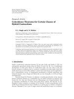
Fig. 1. Bipolar and conventional mono polar battery concepts.
2. Bipolar lead–acid battery concept
The specific power (Wkg
−1
) of a battery is not restricted
by thermodynamics (like the specific energy, Whkg
−1
), but
mainly by the structure and the internal resistance of the
component materials and the cell construction. Thus, for the
lead–acid battery, and indeed for any other battery chem-
istry, there are no principal restrictions to high-power ap-
plications. Of course, the requirement is that under partial
state-of-charge (PSoC) operation there exists an electronic
pathway for conduction. This requires a special paste formu-
lation. Another requirement is that the materials can sustain
long periods under PSoC duty without changes in their prop-
erties.
Since lead–acid batteries are produced on a very large
scale and lead is a cheap material, the units can be corre-
spondingly inexpensive. Furthermore, there exists an infras-
tructure for recycling with very high materials reclamation
percentages (>98%).
In a previous development of a lead–acid battery for mil-
itary pulse–power applications (very high power during mil-
liseconds) TNO has chosen the bipolar concept (see Fig. 1).
This concept is also applicable to hybrid vehicles for the fol-
lowing reasons.
• In principle, no metallic grids are necessary since the cur-
rent is moving perpendicular to the surface from one side
of the bipolar plate to the other.
• A homogeneous current density is present. By contrast,
mono-polar configurations have limited cycle-life (less
than 50 000 cycles) at very high charge and discharge rates
due to sulfation of the lower parts of the pasted plate.
• Production techniques for lead–acid batteries are well de-
veloped and inexpensive, despite the potentially harmful
health properties of lead.
• The internal resistance is much lower than that ofmonopo-
lar designs.
• Lead is a very cheap material. Many other types of bat-
teries use materials that are less abundant (e.g., Ni, Co)
and more costly (or will be when the batteries reach the
mass-production stage).
• There is the possibility of a much higher stack pressure
than in a monopolar design. Of course, this requires the
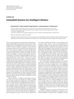
Fig. 2. Power-assist life cycle profile. Positive current=charge of battery
(regenerativebraking);negativecurrent = dischargeofbattery(acceleration).
use of absorptive glass mat separators that can resist the
high pressure.
• Within a single module, or a restricted number of mod-
ules in series, the required voltage can be reached without
external cable connections, etc.
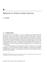
Fig. 3. Photograph of the bipolar lead–acid battery after assembly.
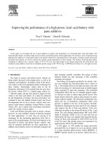
Fig. 4. Photograph of bipolar lead–acid battery under PALC testing.
538 M. Saakes et al. / Journal of Power Sources 144 (2005) 536–545
Fig. 5. EUCAR power-assist life cycle for 12 V, 30 Ah bipolar lead–acid battery.
There are, however, some technical obstacles to overcome
withrespectto thebipolarlead–acid batterybeforesuccessful
commercialization is possible, as follows.
• A corrosion-resistant, lightweight and cheap bipolar plate
material is required. Much work has been under taken to
find a material that meets all these requirements. Up to
now,thishasnotresultedinacommercialbipolarlead–acid
battery system reaching the market; several materials and
otherproblemshavestill tobesolved. Althoughthe bipolar
concept is used, in virtually all types of fuel cell, the ma-
terials are generally not applicable in a lead–acid battery.
This is mainly because of the relatively heavy requirement
for good corrosion resistance in lead–acid batteries (i.e.,
at up to 2.5V per cell in a lead–acid battery as opposed
to less than 1V per cell in a fuel cell). Thus, European
project BILAPS (Bipolar Lead–Acid Power Source, has
been initiated to develop a new mass-production route for
a corrosion–resistant, highly conductive, bipolar plate.
• The application in hybrid vehicles requires>100 000 shal-
low charge–discharge cycles to obtain sufficient battery
lifetime and acceptable cost (of course these criteria also
apply to conventional batteries). Testing is performed us-
ing the power-assist life cycle (PALC).
• The state-of-charge (SoC) during cycling is often held
somewhere in the range of 40–60% and this introduces
the extra risk of recrystallization of lead sulfate during pe-
riods of rest and thereby, to a lowering of the capacity and
Fig. 6. Voltage of 12V, 30 Ah bipolar lead–acid battery, sixteenth hour of test during PALC (see Fig. 4).
M. Saakes et al. / Journal of Power Sources 144 (2005) 536–545 539
Fig. 7. Current profile of 12V, 30 Ah bipolar lead–acid battery, sixteenth hour of test during PALC.
an increaseinthe internal resistance.Formorebackground
information on the bipolar battery, the reader in referred to
[3–14].
3. Test procedure
The bipolar lead–acid battery was tested using the PALC
schedule illustrated in Fig. 2. This drivecycle is comprised of
the following stages: 10C discharge for 18s; pause for 19 s;
charging at 9 C for 4 s; charging at 5 C for 8 s; charging at 2C
for 52 s; pause for 19s.
4. Stack construction
The construction of the bipolar lead–acid battery was
similar to that of fuel cell stacks, i.e., a modular design
(see Figs. 3 and 4). The stack pressure was at a higher
level than in monopolar designs and was achieved by the
use of a special absorptive glass mat (AGM) separator. The
bipolar plate was developed using a new process that of-
fers the possibility of high flexibility in the dimensions of
the bipolar plate. The bipolar plate is stable against cor-
rosion and does not form lead sulfate. The cell is com-
prised of a bipolar plate, spacer, the positive active-mass, the
Fig. 8. Power (negative = discharge of battery,i.e., acceleration;positive = chargeof battery,i.e., regenerative breaking) of 12 V,30 Ah bipolar lead–acid battery,
sixteenth hour of test during PALC.
540 M. Saakes et al. / Journal of Power Sources 144 (2005) 536–545
Fig. 9. Distribution of cell voltages during testing of 12 V, 30 Ah bipolar lead–acid battery during PALC tests at 50% SoC.
negative active-mass, and the AGM separator. Sealing was
achieved with VITON O-rings in order to facilitate easy au-
topsy of the battery; in production, another sealing method
would be used. The end-plates were provided with connec-
tors for high current (300A), voltage measurement and fa-
cilities for cooling by air. The bipolar plates were made with
tabs in order to measure the individual cell voltages during
operation.
Manual stack construction of a 36 V battery took 30 min
for a trained person. In production, the stacking is only a
fraction of this time. The stack was placed under pressure by
means of bolts. In order to measure the internal temperature
(inside the stack), a special Pt-100 sensor was developed, as
well as a dedicated connector to the spacer. With such an
arrangement, it was easy to install or change the Pt-100 in
case of malfunction. The complete stacked was filled (un-
der vacuum) cell-by-cell after verification of the stack resis-
tance (must be infinite before filling) and placing the cell un-
der pressure (sealing must be good before filling). After fill-
ing, the open-circuit voltage (OCV) was measured together
with the internal resistance at 1000Hz(Hewlett-Packard mil-
liohmmeter). After this, the stack was allowed to rest. A refill
was performed 2 days later and was followed by constant-
current (CC) and constant-voltage (CV) charging. In order
to prevent sulfate build up, an electronic device with high
frequency pulses was connected to the battery directly after
the final filling. The device is commercially available (Power
Pulse) [15].
Fig. 10. Voltage of 12V, 30 Ah bipolar lead–acid battery during PALC tests at 50% SoC for single cycle during the sixteenth hour.
M. Saakes et al. / Journal of Power Sources 144 (2005) 536–545 541
Fig. 11. Power profile during single cycle (positive = charge; negative= discharge) given by 12 V, 30Ah bipolar lead–acid battery; sixteenth hour of PALC test.
5. Testing of 12 V 30 Ah bipolar lead–acid battery
using PALC schedule
The 12 V, 30Ah bipolar lead–acid battery was discharged
at aC/3rate until50%SoC wasreached.The battery was then
tested under the EUCAR profile, as shown in Fig. 5, using
10 C discharge peaks and 9 C charge peaks. The tests were
performed for 16 h and were followed by a period of rest
for 8h. The PALC tests were continued and the maximum
temperature rise during 16h of continuous testing was less
than 20
◦
C.
The voltage of the 12 V battery during testing is given in
Fig. 6. The minimum voltage is 8.6 V at 300 A discharge
during 18s and a SoC of about 50%. No problems were
found with low voltage limits during the tests. The current
profile is given in Fig. 7 while the corresponding power
profile, as measured, is shown in Fig. 8. The maximum
power generated by the 12V bipolar lead–acid battery is ap-
proximately 3.3 kW see Fig. 8. This is equivalent to 10 kW
for a 36 V module. For the PALC, 10kW of power is re-
quired. Thus, at 50% SoC, the tested 12V, 30 Ah bipolar bat-
tery fulfills the power requirement. More importantly, charg-
Fig. 12. Internal cell temperature (cell 3) during sixteenth hour of PALC test for 12V, 30 Ah bipolar lead–acid battery at about 25
◦
C and with air-cooling on
the outside.
542 M. Saakes et al. / Journal of Power Sources 144 (2005) 536–545
Fig. 13. Cell voltages on single PALC cycle during sixteenth hour of continuous operation for 12V, 30 Ah bipolar lead–acid battery.
ing with 9 C peaks during 4 s has been demonstrated to be
feasible.
The single-cell voltages given in Fig. 9 show only a rel-
atively small variation. Because the battery was hand-made,
differences in cell behavior will always exist. The minimum
voltage during 18 s of 300A discharge at a maximum 50%
SoC is above 1.35V per cell. The maximum cell voltage is
2.6 V per cell at 9 C charge during 4 s at 50% SoC. Of course,
the cell voltages have to be corrected for the internal resis-
tance per cell to determine the resistance-free charge and
discharge voltage. The internal resistance is about 0.94 m
per cell at 50% SoC. At 300 A discharge, the ohmic volt-
age drop is 0.28V. The cell voltage corrected for the internal
resistance during discharge is then equal to 1.63 V. In case
of 300A discharge, this value is not too low for operation.
The charging at 9 C can also be corrected for the ohmic volt-
age contribution. In this case, the ohmic voltage increase is
0.25 V and therefore the charge voltage at the 9 C rate is
2.35 V per cell. This value is still below the gassing voltage.
The voltage profile for one PALC is presented in Fig. 10. The
minimum voltage, during discharge at 10 C (300 A), is equal
to about 8.7 V. This discharge is under taken while the bat-
tery operates at about 50% SoC. The current density is about
0.4Acm
−2
.
During PALC tests, started at 50% SoC, the bipolar
lead–acid battery shows stable operation without decreases
Fig. 14. Voltage vs. time for 36V, 32 Ah bipolar lead–acid battery during eight hours of PALC test with 7C discharge and 6.3C charge peaks.
M. Saakes et al. / Journal of Power Sources 144 (2005) 536–545 543
Fig. 15. Current vs. time for 36V, 32 Ah bipolar lead–acid battery during eight hours of PALC test with 7C discharge and 6.3C charge peaks.
in cell voltage. An example of the power profile for the 12V
stack is presented in Fig. 11. It is remarkable that the bipo-
lar lead–acid battery readily accepts very high charging rates
(9 C during 4 s) and also delivers 10C discharge peaks dur-
ing 18 s while being at only a maximum of 50% SoC. This
means that the formation of lead sulfate does not inhibit the
passage of high currents. This is due to the fact that con-
ducting pathways are present in the form of a stable con-
ductor added to the paste. Another point is that due to the
operation at 50% SoC, corrosion processes are less severe
than in operation at almost 100% SoC as is experienced in
uninterruptible power supply and automotive applications
where the battery is held at (almost) full charge. The rel-
atively high compression of the positive active-material is
another important features has been included in the design
of the battery. Differences in acid concentration due to strat-
ification have also been addressed. For this reason, the 12 V,
30 Ah battery (Fig. 2) has been operated horizontally. This
orientation also reduces strongly the risk of active-material
shedding and the oxygen cycle is improved. Importantly, the
bipolar configuration leads to a homogeneous current dis-
tribution. The internal heating is also lowered using a bipo-
lar configuration and this decreases the internal resistance,
which has been further decreased by adding conductive ad-
ditives to the paste and by applying a technique to counteract
there-crystallizationprocess.Finally,abattery-management-
system at the cell level has been applied to optimize the cell
behaviour.
Fig. 16. Power vs. time for 36V, 32 Ah bipolar lead–acid battery during eight hours of PALC test with 7C discharge and 6.3C charge peaks.
544 M. Saakes et al. / Journal of Power Sources 144 (2005) 536–545
Fig. 17. Cell voltages vs. time for 36 V, 32 Ah bipolar lead–acid battery during eight hours of PALC test with 7 C discharge and 6.3 C charge peaks.
The internal cell temperature during continuous operation
onaPALC cycleis showninFig.12.Duringdischarge(18 s at
300 A), the internal temperature decreases as expected. Dur-
ing charge, the internal temperature increases. The temper-
ature during operation stabilizes at about 15 to 18
◦
C above
room temperature. During one run, the ambient was 30
◦
C
and this resulted in a battery temperature of 48
◦
C. This is
well below the temperature of 70
◦
C when tribasic lead sul-
fate changes into tetrabasic lead sulfate, i.e., the conversion
only takes place at elevated temperatures that normally do
not occur during battery operation. The tribasic lead sulfate
is present due to the manufacturing method used. Of course,
during plate formation, all of the tribasic lead sulfate is con-
verted to active material. During partial state-of-charge duty,
tribasic lead sulfate is formed. Further investigations are re-
quired to determine the exact composition of the positive and
negative plate during hybrid operation. It is postulated that
material withahigh surfaceareamaterial is formedasa result
ofPALCoperationwith 9C chargeand 10 Cdischarge.When
the temperature becomes too high, the power has to be de-
creased. The temperaturerisecanbe lowered byothermeans,
e.g., by increasing the conductivity of the bipolar plate. For
the 36 V module (see later), the internal resistance was fur-
ther loweredto0.5 m percell,and moresuchimprovements
are underway. There is also scope to improve the thermal
management system. In this way, the battery can be operated
even at outside temperatures that are higher than 30
◦
C with-
out causing problems with charge acceptance (regenerative
breaking) or charge delivery (acceleration). The cell voltages
of a 12 V module during one PALC are shown in Fig. 13.
The maximum voltage is 2.6V. The internal resistance of the
cell is approximately 0.9m. The ohmic cell voltage drop
or increase is about 0.3 V. This means that the cell voltage
corrected for the ohmic voltage contribution is about 2.3V
during charge (9C charge peak) and 1.7V during discharge
(10 C discharge peak). This voltage window (1.7 to 2.3V)
enables stable operation as is found by the stable continuous
operation during 16 h.
6. PALC testing of 36 V, 30Ah bipolar lead–acid
battery
After construction and testing of 4 V and 12 V bipolar bat-
teries (30 Ah), two 36 V versions were assembled from op-
timized bipolar plates. Testing with 10 C discharge and 9 C
charge peaks resulted in heating of the battery due to the fact
that the thermal management system required further devel-
opment. Therefore, it was decided to perform PALC with 7 C
discharge peaks and 6.3 C charge peaks. The battery exhib-
ited a stable operational temperature. The voltage, current
and power profiles of the 36 V, 32 Ah bipolar battery dur-
ing 1h of the PALC test after 7 h of running are presented
in Figs. 14–16 respectively. The individual cell voltages are
shownin Fig. 17.Thedata indicatethatthe bipolar batteryex-
periences a stable operation and gives rise to no problems of
overvoltageor undervoltage.Improvementsarein progressto
decrease further the internal cell resistance and to optimize
the installed capacity of the positive active-mass, negative
active-mass, and the acid present.
7. Conclusions
From initial tests of a novel bipolar lead–acid technol-
ogy that uses AGM separator technology, it has been demon-
strated that continuous testing for 16 h at 50% SoC with 10 C
discharge pulses (18s) and 9 C charge pulses (4 s) of a 12 V,
30 Ah battery gives stable behaviour, even when the outside
temperature is 30
◦
C. The re-crystallization phenomenon is
M. Saakes et al. / Journal of Power Sources 144 (2005) 536–545 545
actively counteracted by using electric pulses applied to the
battery at 50% SoC. PALC to date the 12 V, 30 Ah bipolar
battery has operated without any problems and with no de-
cay in capacity after more than 7000 PALCs, each of 2 min
duration. The total Ah-throughput is more than 350 times
the nominal capacity of 30 Ah. Some differences in cell be-
havior have been found, but can be attributed to the man-
ual way of assembling. Further tests are being conducted to
improve the technology, especially in terms of lowering the
internal resistance and reducing the weight of the bipolar
cell module.
Acknowledgements
The project is partly funded by the European Commis-
sion in the 5th Framework Program: Energy, Environment
and Sustainable Development (contract no. ENK6-CT-2001-
00544). The publication does not represent the opinion of the
European Community and the European Community is not
responsible for any use that might be made of data appearing
in this publication. The partners in the project are CRF (Fiat),
IMTECH, ElringKlinger, Dyneon, PGE, SCPS, A2E, Centu-
rion Akku. They are thanked for their valuable contributions
to the project in their field of expertise.
References
[1] Proceedings of AABC-02, 4–7 February 2002, Las Vegas, USA.
[2] Proceedings of AABC-03, June 2003, Nice, France.
[3] />03/presentation
effpower.pdf.
[4] />[5] />[6] />[7] US Patent 6,077,623 Bipolar lead–acid battery plates and method of
making same.
[8] A. Cooper, J. Power Sources 133 (2004) 116–125.
[9] V. Toniazzo, U. Lambert, J. Power Sources 133 (2004) 94–103.
[10] D. Pavlov, I. Pashmakova, J. Appl. Electrochem. 17 (1987)
1075–1082.
[11] P.T. Moseley, D.A.J. Rand, J. Power Sources 133 (2004) 104–109.
[12] J.H. Yan, W.S. Li, Q.Y. Zhan, J. Power Sources 133 (2004) 135–140.
[13] L.T. Lam, N.P. Haigh, C.G. Phyland, A.J. Urban, J. Power Sources
133 (2004) 126–134.
[14] D. Edwards, C. Kinney, Final Report (Report Number N01–11),
Advanced Lead–Acid Battery Development, NIATI, March 2001.
[15] />sheets/PRS
LIT.pdf.