rf mems and their applications
Bạn đang xem bản rút gọn của tài liệu. Xem và tải ngay bản đầy đủ của tài liệu tại đây (5.73 MB, 408 trang )
RF MEMS
and Their Applications
RF MEMS
and Their Applications
Vijay K. Varadan
K.J. Vinoy
K.A. Jose
Pennsylvania State University, USA
Copyright 2003 John Wiley & Sons Ltd, The Atrium, Southern Gate, Chichester,
West Sussex PO19 8SQ, England
Telephone (+44) 1243 779777
Email (for orders and customer service enquiries):
Visit our Home Page on www.wileyeurope.com or www.wiley.com
Reprinted April 2003
All Rights Reserved. No part of this publication may be reproduced, stored in a retrieval system or
transmitted in any form or by any means, electronic, mechanical, photocopying, recording, scanning or
otherwise, except under the terms of the Copyright, Designs and Patents Act 1988 or under the terms of
a licence issued by the Copyright Licensing Agency Ltd, 90 Tottenham Court Road, London W1T 4LP,
UK, without the permission in writing of the Publisher. Requests to the Publisher should be addressed
to the Permissions Department, John Wiley & Sons Ltd, The Atrium, Southern Gate, Chichester, West
Sussex PO19 8SQ, England, or emailed to , or faxed to (+44) 1243 770620.
This publication is designed to provide accurate and authoritative information in regard to the subject
matter covered. It is sold on the understanding that the Publisher is not engaged in rendering
professional services. If professional advice or other expert assistance is required, the services of a
competent professional should be sought.
Other Wiley Editorial Offices
John Wiley & Sons Inc., 111 River Street, Hoboken, NJ 07030, USA
Jossey-Bass, 989 Market Street, San Francisco, CA 94103-1741, USA
Wiley-VCH Verlag GmbH, Boschstr. 12, D-69469 Weinheim, Germany
John Wiley & Sons Australia Ltd, 33 Park Road, Milton, Queensland 4064, Australia
John Wiley & Sons (Asia) Pte Ltd, 2 Clementi Loop #02-01, Jin Xing Distripark, Singapore 129809
John Wiley & Sons Canada Ltd, 22 Worcester Road, Etobicoke, Ontario, Canada M9W 1L1
Wiley also publishes its books in a variety of electronic formats. Some content that appears
in print may not be available in electronic books.
Library of Congress Cataloging-in-Publication Data
Varadan, V.K., 1943–
RF MEMS and their applications / Vijay K. Varadan, K.J. Vinoy, and K.A. Jose.
Includes bibliographical references and index.
ISBN 0-470-84308-X (alk. paper)
1. Radio circuits–Equipment and supplies. 2. Microelectromechanical systems. 3. Microwave
circuits. I. Vinoy, K.J. (Kalarickaparambil Joseph), 1969– II. Jose K. Abraham. III. Title.
TK6560.V33 2002
621.384
13–dc21 2002071393
British Library Cataloguing in Publication Data
A catalogue record for this book is available from the British Library
ISBN 0-470-84308-X
Typeset in 10/12pt Times by Laserwords Private Limited, Chennai, India
Printed and bound in Great Britain by Biddles Ltd, Guildford and King’s Lynn
This book is printed on acid-free paper responsibly manufactured from sustainable forestry
in which at least two trees are planted for each one used for paper production.
Contents
Preface xi
1 Microelectromechanical systems (MEMS) and radio frequency
MEMS 1
1.1 Introduction 1
1.2 MEMS 2
1.3 Microfabrications for MEMS 5
1.3.1 Bulk micromachining of silicon 5
1.3.2 Surface micromachining of silicon 8
1.3.3 Wafer bonding for MEMS 9
1.3.4 LIGA process 11
1.3.5 Micromachining of polymeric MEMS devices 13
1.3.6 Three-dimensional microfabrications 15
1.4 Electromechanical transducers 16
1.4.1 Piezoelectric transducers 18
1.4.2 Electrostrictive transducers 20
1.4.3 Magnetostrictive transducers 22
1.4.4 Electrostatic actuators 24
1.4.5 Electromagnetic transducers 27
1.4.6 Electrodynamic transducers 29
1.4.7 Electrothermal actuators 32
1.4.8 Comparison of electromechanical actuation schemes 34
1.5 Microsensing for MEMS 35
1.5.1 Piezoresistive sensing 35
1.5.2 Capacitive sensing 37
1.5.3 Piezoelectric sensing 37
1.5.4 Resonant sensing 38
1.5.5 Surface acoustic wave sensors 38
1.6 Materials for MEMS 42
1.6.1 Metal and metal alloys for MEMS 42
1.6.2 Polymers for MEMS 42
1.6.3 Other materials for MEMS 44
1.7 Scope of this book 44
References 45
vi CONTENTS
2 MEMS materials and fabrication techniques 51
2.1 Metals 51
2.1.1 Evaporation 51
2.1.2 Sputtering 53
2.2 Semiconductors 54
2.2.1 Electrical and chemical properties 54
2.2.2 Growth and deposition 57
2.3 Thin films for MEMS and their deposition techniques 61
2.3.1 Oxide film formation by thermal oxidation 61
2.3.2 Deposition of silicon dioxide and silicon nitride 62
2.3.3 Polysilicon film deposition 64
2.3.4 Ferroelectric thin films 64
2.4 Materials for polymer MEMS 67
2.4.1 Classification of polymers 67
2.4.2 UV radiation curing 74
2.4.3 SU-8 for polymer MEMS 80
2.5 Bulk micromachining for silicon-based MEMS 84
2.5.1 Isotropic and orientation-dependent wet etching 84
2.5.2 Dry etching 88
2.5.3 Buried oxide process 88
2.5.4 Silicon fusion bonding 89
2.5.5 Anodic bonding 90
2.6 Silicon surface micromachining 91
2.6.1 Sacrificial layer technology 91
2.6.2 Material systems in sacrificial layer technology 92
2.6.3 Surface micromachining using plasma etching 93
2.6.4 Combined integrated-circuit technology
and anisotropic wet etching 94
2.7 Microstereolithography for polymer MEMS 94
2.7.1 Scanning method 95
2.7.2 Two-photon microstereolithography 96
2.7.3 Surface micromachining of polymer MEMS 97
2.7.4 Projection method 97
2.7.5 Polymeric MEMS architecture with silicon, metal
and ceramics 102
2.7.6 Microstereolithography integrated with thick-film
lithography 105
2.8 Conclusions 105
References 105
3 RF MEMS switches and micro relays 109
3.1 Introduction 109
3.2 Switch parameters 111
3.3 Basics of switching 115
3.3.1 Mechanical switches 116
3.3.2 Electronic switches 117
CONTENTS vii
3.4 Switches for RF and microwave applications 117
3.4.1 Mechanical RF switches 118
3.4.2 PIN diode RF switches 119
3.4.3 Metal oxide semiconductor field effect transistors
and monolithic microwave integrated circuits 123
3.4.4 RF MEMS switches 124
3.4.5 Integration and biasing issues for RF switches 125
3.5 Actuation mechanisms for MEMS devices 127
3.5.1 Electrostatic switching 128
3.5.2 Approaches for low-actuation-voltage switches 141
3.5.3 Mercury contact switches 146
3.5.4 Magnetic switching 148
3.5.5 Electromagnetic switching 148
3.5.6 Thermal switching 151
3.6 Bistable micro relays and microactuators 152
3.6.1 Magnetic actuation in micro relays 152
3.6.2 Relay contact force and materials 156
3.7 Dynamics of the switch operation 157
3.7.1 Switching time and dynamic response 158
3.7.2 Threshold voltage 160
3.8 MEMS switch design, modeling and evaluation 162
3.8.1 Electromechanical finite element analysis 163
3.8.2 RF design 165
3.9 MEMS switch design considerations 174
3.10 Conclusions 175
References 178
4 MEMS inductors and capacitors 183
4.1 Introduction 183
4.2 MEMS/micromachined passive elements: pros and cons 184
4.3 MEMS inductors 184
4.3.1 Self-inductance and mutual inductance 185
4.3.2 Micromachined inductors 188
4.3.3 Effect of inductor layout 194
4.3.4 Reduction of stray capacitance of planar
inductors 198
4.3.5 Approaches for improving the quality factor 200
4.3.6 Folded inductors 211
4.3.7 Modeling and design issues of planar inductors 212
4.3.8 Variable inductors 215
4.3.9 Polymer-based inductors 215
4.4 MEMS capacitors 215
4.4.1 MEMS gap-tuning capacitors 217
4.4.2 MEMS area-tuning capacitors 224
4.4.3 Dielectric tunable capacitors 228
4.5 Conclusions 229
References 235
viii CONTENTS
5 Micromachined RF filters 241
5.1 Introduction 241
5.2 Modeling of mechanical filters 244
5.2.1 Modeling of resonators 244
5.2.2 Mechanical coupling components 251
5.2.3 General considerations for mechanical filters 257
5.3 Micromechanical filters 258
5.3.1 Electrostatic comb drive 258
5.3.2 Micromechanical filters using comb drives 260
5.3.3 Micromechanical filters using electrostatic coupled
beam structures 265
5.4 Surface acoustic wave filters 268
5.4.1 Basics of surface acoustic wave filter operation 269
5.4.2 Wave propagation in piezoelectric substrates 270
5.4.3 Design of interdigital transducers 271
5.4.4 Single-phase unidirectional transducers 274
5.4.5 Surface acoustic wave devices: capabilities, limitations
and applications 275
5.5 Bulk acoustic wave filters 276
5.6 Micromachined filters for millimeter wave frequencies 278
5.7 Summary 282
References 283
6 Micromachined phase shifters 285
6.1 Introduction 285
6.2 Types of phase shifters and their limitations 286
6.2.1 Ferrite phase shifters 287
6.2.2 Semiconductor phase shifters 287
6.2.3 Ferroelectric thin-film phase shifters 288
6.2.4 Limitations of phase shifters 288
6.3 MEMS phase shifters 289
6.3.1 Switched delay line phase shifters 289
6.3.2 Distributed MEMS phase shifters 289
6.3.3 Polymer-based phase shifters 296
6.4 Ferroelectric phase shifters 298
6.4.1 Distributed parallel plate capacitors 299
6.4.2 Bilateral interdigital phase shifters 301
6.4.3 Interdigital capacitor phase shifters 304
6.5 Applications 305
6.6 Conclusions 305
References 306
7 Micromachined transmission lines and components 309
7.1 Introduction 309
7.2 Micromachined transmission lines 310
7.2.1 Losses in transmission lines 311
7.2.2 Co-planar transmission lines 313
CONTENTS ix
7.2.3 Microshield and membrane-supported
transmission lines 316
7.2.4 Microshield circuit components 321
7.2.5 Micromachined waveguide components 324
7.2.6 Micromachined directional couplers 327
7.2.7 Micromachined mixer 327
7.2.8 Passive components: resonators and filters 330
7.2.9 Micromachined antennae 332
7.3 Design, fabrication and measurement 334
7.3.1 Design 335
7.3.2 Fabrication 335
7.3.3 Evaluation 335
7.4 Conclusions 337
References 338
8 Micromachined antennae 343
8.1 Introduction 343
8.2 Overview of microstrip antennae 344
8.2.1 Basic characteristics of microstripeantennae 344
8.2.2 Design parameters of microstrip antennae 347
8.3 Micromachining techniques to improve antenna performance 351
8.4 Micromachining as a fabrication process for small antennae 356
8.5 Micromachined reconfigurable antennae 360
8.6 Summary 362
References 363
9 Integration and packaging for RF MEMS devices 365
9.1 Introduction 365
9.2 Role of MEMS packages 366
9.2.1 Mechanical support 366
9.2.2 Electrical interface 367
9.2.3 Protection from the environment 367
9.2.4 Thermal considerations 367
9.3 Types of MEMS packages 367
9.3.1 Metal packages 368
9.3.2 Ceramic packages 368
9.3.3 Plastic packages 368
9.3.4 Multilayer packages 369
9.3.5 Embedded overlay 369
9.3.6 Wafer-level packaging 370
9.3.7 Microshielding and self-packaging 372
9.4 Flip-chip assembly 373
9.5 Multichip module packaging 375
9.5.1 Wafer bonding 377
9.6 RF MEMS packaging: reliability issues 380
9.6.1 Packaging materials 380
9.6.2 Integration of MEMS devices with microelectronics 380
x CONTENTS
9.6.3 Wiring and interconnections 382
9.6.4 Reliability and key failure mechanisms 382
9.7 Thermal issues 383
9.8 Conclusions 383
References 384
Index 387
Preface
The market for wireless personal communication devices has expanded so dramatically
in the past two decades that the focus of research in the microwave and millimeter
wave areas has shifted towards consumer applications, from the more traditional defense-
related products. Accordingly, the production volume has increased manifold, while the
power-handling capacity required for these systems has considerably reduced. These
developments paved the way for increased application of microelectromechanical systems
(MEMS) in many current and future radio frequency (RF), microwave and millime-
ter wave systems. Such devices are termed RF MEMS, although it encompasses all
miniaturized devices; whether they are operated micromechanically, or fabricated by
micromachining, or both. Fortunately enough, the processing techniques for MEMS sys-
tems have improved significantly over the years, and we are increasingly leaning towards
their applications in microwave and millimeter wave systems, and even in optical systems.
Apart from having the advantages of bulk production, and being miniaturized, these can
often lead to more efficient systems compared with conventional ones.
The need for micromachining and MEMS based systems for RF and microwave
applications arise from the inherent limitations of the existing devices. Motivations for
incorporating MEMS based fabrication technologies in microwave and millimeter wave
systems can broadly be classified into three. First, as the frequency increases, the size
of the microwave components becomes smaller. Thus, for millimeter wave systems it is
imperative that dimensions of most of the components are in the sub-millimeter range.
This calls for high-precision fabrication technologies for which micromachining offers
a viable route. In addition, this approach provides system integration capabilities. At
lower frequencies (wavelength of the order of 1 to 2 cm) efforts have been made towards
implementing micromachining techniques to concomitantly reduce the effective dielec-
tric constant of the microstrip antenna substrate. Micromachining of these substrates not
only does improve the radiation efficiency of the antenna, but also increases the band-
width. Many MEMS based microwave components are aimed at reducing insertion loss
and increasing bandwidth. This third aspect is valid for surface micromachined devices
such as RF switches, tunable capacitors and micro inductors. Conventional RF switching
systems such as PIN diodes tend to be inefficient at higher frequencies. MEMS based
RF switches with very low actuation voltages have been reported recently. At microwave
frequencies, micromachined lumped components can replace distributed components with
flexibility in integration as well as improvement in bandwidth. Similarly, micromachined
or MEMS based phase shifters can replace existing configurations, which tend to have
higher insertion losses at high gigahertz frequencies. It may also be noted that micro
xii PREFACE
fabrication technologies can help realize high Q micromechanical filters for frequencies
up to and beyond 10 MHz, and micromachined surface acoustic wave (SAW) filters fill-
ing the gap up to 2 GHz. Fabrication processes for all these devices and their relative
advantages are taken up extensively in this book. In addition, a brief description of pack-
aging approaches that may be extended for these devices is also included for the sake of
comprehensiveness in coverage.
We have endeavoured to present these topics so as to guide graduate students inter-
ested to do research in microfabrication techniques and their applications. It is therefore
envisaged that parts of this books would form the curricula of electrical and mechanical
engineering, applied physics or materials science departments. In addition, this would also
serve as a reference book for practicing researchers in these areas for further widening
the scope of their research.
Materials for this book have been taken from an advanced level course offered at
Pennsylvania State University recently on RF MEMS, and many short courses presented
across the world. Valuable comments from the participants of these courses have helped in
evolving the contents of this book and are greatly appreciated. In particular we also wish
to thank many of our colleagues and students, Taeksoo Ji, Yanan Sha, Roopa Tellakula,
Hargsoon Yoon, and Bei Zhu, at the Center for Electronic and Acoustic Materials and
Devices for their contributions in preparing the manuscript for this book.
We would like to thank Professors Vasundara V. Varadan and Richard McNitt for
their support and encouragement. Our thanks are also due to our families, in particular
Nisy John, for bearing with our preoccupation in preparing this manuscript. We are also
indebted to various researchers for their valuable contributions cited in this book.
We are also grateful to the publisher’s staff for their support, encouragement and
willingness to give prompt assistance during this book project.
Vijay K. Varadan
K.J. Vinoy
K.A. Jose
1
Microelectromechanical systems
(MEMS) and radio frequency
MEMS
1.1 INTRODUCTION
During the past decade, several new fabrication techniques have evolved which helped
popularize microelectromechanical systems (MEMS), and numerous novel devices have
been reported in diverse areas of engineering and science. One such area is microwave
and millimeter wave systems. MEMS technology for microwave applications should solve
many intriguing problems of high-frequency technology for wireless communications. The
recent and dramatic developments of personal communication devices forced the market
to acquire miniaturized efficient devices, which is possible only by the development of
radio frequency (RF) MEMS.
The term RF MEMS refers to the design and fabrication of MEMS for RF integrated
circuits. It should not be interpreted as the traditional MEMS devices operating at RF fre-
quencies. MEMS devices in RF MEMS are used for actuation or adjustment of a separate
RF device or component, such as variable capacitors, switches, and filters. Traditional
MEMS can be divided into two classes: MEMS actuators and MEMS sensors. The first
one is a kind of moving mechanism activated by an electrical signal like Micromotor.
Micro sensors are currently available for a large number of applications. Historically,
owing to their ease of fabrication, these were the earliest microsystems. Another reason
for the actuators not becoming popular is that the amount of energy generated by such
tiny systems does not cause much impact in the associated systems. However, it can
be seen later, for microwave and millimeter wave systems, these forces are sufficient to
change the properties of overall systems. Passive devices include bulk micromachined
transmission lines, filters and couplers. Active MEMS devices include switches, tuners
and variable capacitors. The electromotive force used to move the structures on the wafer
surface is typically electrostatic attraction, although magnetic, thermal or even gas-based
microactuator structures have been developed.
Following the classical review paper by Brown (1998), the RF MEMS development
to date can be classified into the following categories based on whether one takes an RF
or MEMS view point: (1) RF extrinsic in which the MEMS structure is located outside
the RF circuit and actuates or controls other devices in the RF circuit. In this class,
one would consider the example of a tunable microstrip transmission line and associated
2 MEMS AND RF MEMS
phased shifters and arrays. Microstrip lines are extensively used to interconnect high-speed
circuits and components because they can be fabricated by easy automated techniques.
(2) RF intrinsic in which the MEMS structure is located inside the RF circuit and has
both the actuation and RF-circuit function. In this class, one could consider traditional
cantilever and diaphragm type MEMS which can be used as electrostatic microswitch
and comb-type capacitors (Brown, 1998). With the invention of electroactive polymers
(EAPs), multifunctional smart polymers and microstereo lithography, these types of RF
MEMS can be easily conceived with polymer-based systems. They are also flexible, stable
and long lasting. Moreover, they can be integrated with the organic thin film transistor.
(3) RF reactive in which the MEMS structure is located inside, where it has an RF
function that is coupled to the attenuation. In this class, capacitively coupled tunable
filters and resonators provide the necessary RF function in the circuit. Microwave and
millimeter wave planar filters on thin dielectric membrane show low loss, and are suitable
for low-cost, compact, high-performance mm-wave one-chip integrated circuits.
One of the earliest reported applications of silicon-based RF MEMS technology for
microwave applications is in the area of surface micromachined actuators for the real-
ization of microwave switches. These possess very high linearity, low dc standby power
and low insertion loss (Larson, 1999). These switches are based on electrostatic attrac-
tion counterbalanced by suitable mechanical forces on the beam to pull the switch into
the right position. This switch can be designed to present nearly 50 impedance across
a broad range of frequencies when closed, and nearly an open circuit when there is no
connection. This property makes this an attractive choice for microwave applications. Sev-
eral new switch architectures have also been reported, including the air-bridge structure
(Goldsmith, Eshelman and Dennston, 1998). This structure utilizes very high capacitance
variation to achieve the switching action. This scheme, however, suffers from relatively
high switching voltage requirements.
MEMs technology is also used for RF applications in the area of variable capacitors,
as a replacement for varactor diodes as tuners (Wu et al., 1998). Here, either a lateral or a
parallel plate capacitance variation can be obtained with suitable fabrication approaches.
The capacitance variation in the parallel plate version is over 3 : 1 making them attractive
for wide-band tuning of monolithic voltage-controlled oscillators (VCOs). However their
range is often limited by the low-frequency mechanical resonance of the structure.
1.2 MEMS
The term MEMS refers to a collection of microsensors and actuators which can sense its
environment and have the ability to react to changes in that environment with the use of
a microcircuit control. They include, in addition to the conventional microelectronics
packaging, integrating antenna structures for command signals into micro electrome-
chanical structures for desired sensing and actuating functions. The system also may
need micropower supply, micro relay and microsignal processing units. Microcompo-
nents make the system faster, more reliable, cheaper and capable of incorporating more
complex functions.
In the beginning of the 1990s, MEMS emerged with the aid of the development of inte-
grated circuit (IC) fabrication processes, where sensors, actuators and control functions are
co-fabricated in silicon. Since then, remarkable research progresses have been achieved in
MEMS under strong capital promotions from both government and industry. In addition to
MEMS 3
the commercialization of some less-integrated MEMS devices, such as microaccelerome-
ters, inkjet printer heads, micro mirrors for projection, etc., the concepts and feasibility of
more complex MEMS devices have been proposed and demonstrated for the applications
in such varied fields as microfluidics, aerospace, biomedicine, chemical analysis, wireless
communications, data storage, display, optics, etc. (Fujita, 1996, 1998). Some branches
of MEMS, such as micro-opto-electromechanical systems (MOEMS), micro total analysis
systems (µTAS), etc., have attracted a great deal of research interest since their poten-
tial application market. As of the end of the 1990s, most MEMS devices with various
sensing or actuating mechanisms were fabricated using silicon bulk micromachining, sur-
face micromachining and LIGA
1
processes (Bustillo, Howe and Muller, 1998; Guckel,
1998; Kovacs, Maluf and Petersen, 1998). Three dimensional microfabrication processes
incorporating more materials were presented for MEMS recently when some specific
application requirements (e.g. biomedical devices) and microactuators with higher output
power were called for in MEMS (Fujita, 1996; Guckel, 1998; Ikuta and Hirowatari, 1993;
Takagi and Nakajima, 1993; Taylor et al., 1994; Thornell and Johansson, 1998; Varadan
and Varadan, 1996; Xia and Whitesides, 1998).
Micromachining has become the fundamental technology for the fabrication of micro-
electromechanical devices and, in particular, miniaturized sensors and actuators. Silicon
micromachining is the most mature of the micromachining technologies and it allows for
the fabrication of MEMS that have dimensions in the submillimeter range. It refers to
fashioning microscopic mechanical parts out of silicon substrate or on a silicon substrate,
making the structures three dimensional and bringing new principles to the designers.
Employing materials such as crystalline silicon, polycrystalline silicon and silicon nitride,
etc., a variety of mechanical microstructures including beams, diaphragms, grooves, ori-
fices, springs, gears, suspensions and a great diversity of other complex mechanical
structures has been conceived (Bryzek, Peterson and McCulley, 1994; Fan, Tai and Muller,
1987; Middelhoek and Audet, 1989; Peterson, 1982; Varadan, Jiang and Varadan, 2001).
Sometimes many microdevices can also be fabricated using semiconductor process-
ing technologies or stereolithography on the polymeric multifunctional structures. Stere-
olithography is a poor man’s LIGA for fabricating high aspect ratio MEMS devices
in UV-curable semi-conducting polymers. With proper doping, a semiconducting poly-
mer structure can be synthesized and using stereo lithography it is now possible to
make three-dimensional microstructures of high aspect ratio. Ikuta and Hirowatari (1993)
demonstrated that a three-dimensional microstructure of polymers and metal is feasible
using a process named IH Process (integrated hardened polymer stereolithography). Using
a UV light source, XYZ-stage, shutter, lens and microcomputer, they have shown that
microdevices such as springs, venous valves and electrostatic microactuators can be fab-
ricated. In case of difficulty on the polymeric materials, some of these devices can be
micromachined in silicon and the system architecture can be obtained by photoforming
or hybrid processing (Ikuta and Hirowatari, 1993; Takagi and Nakajima, 1993; Tani and
Esashi, 1995; Varadan, 1995; Varadan and Varadan, 1995, 1996). The photoforming or
photo fabrication is an optical method such as the stereolithography, photo mask layer-
ing process and IH process which involves solidification of photochemical resin by light
exposure. Takagi and Nakajima (1993) proposed new concepts of ‘combined architecture’
1
LIGA is a German acronym, for Lithographie, Galvanoformung, Abformung (lithography, galvanoforming,
moulding)
4 MEMS AND RF MEMS
and ‘glue mechanism’ using the photoforming process to fabricate complicated structures
by combining components, each of them made by its best fabrication process. Batch
processing of such hybrid silicon and polymer devices thus seems feasible.
The combined architecture may also result in sheets of smart skin with integrated sen-
sors and actuators at the µm to mm scale. For some applications (say airfoil surface), the
smart skin substrate has to be flexible to conform to the airfoil shape and at the same time
it has to be compatible with the IC processing for sensor and smart electronics integration.
It has been proposed by Carraway (1991) that polyimide is an excellent material for use
as the skin because of its flexibility and IC processing compatibility. The control loop
between the sensors and actuators employs the multifunctional materials which provide
electrical functionality at selected locations using conductive polymers and electrodes that
are connected to on-site antennas communicating with a central antenna. A related and
difficult problem, and one which has been largely unaddressed, is the method for telemetry
of the data. In some applications, stresses and strains to which the structure is subjected
may pose a problem for conventional cabling. In others, environmental effects may affect
system performance. Advances in ultra flat antenna technology coupled with MEMS sen-
sors/actuators seems to be an efficient solution. The integration of micromachining and
microelectronics on one chip results in so-called smart sensors. In smart sensors, small
sensor signals are amplified, conditioned and transformed into a standard output format.
They may include microcontroller, digital signal processor, application-specific integrated
circuit (ASIC), self-test, self-calibration and bus interface circuits, simplifying their use
and making them more accurate and reliable.
The basic MEMS utilize a diaphragm-based, a microbridge-based or a cantilever-based
structure. Special processing steps commonly known as micromachining are needed to
fabricate these membranes, cantilever beams, resonant structures, etc., which will be
discussed later. For a given application, it may be necessary to have integrated MEMS
employing one or more of the basic structures. These three structures provide some
feasible designs for microsensors and actuators that eventually perform the desired task
in most smart structures. However, the main issues with respect to implementing these
structures are the choice of materials that are to be used in fabricating these devices and
the micromachining technology that may be utilized. To address the first issue, we note
that in all of the three structures proposed the sensing and actuation occur as a result
of exciting a piezoelectric layer by the application of an electric field. This excitation
brings about sensing and actuation in the form of expansion in the diaphragm, or in
the free-standing beam in the microbridge structure, or in the cantilever beam. In the
former two cases the expansion translates into upward curvature in the diaphragm or in
the free-standing beam, hence resulting in a net vertical displacement from the unexcited
equilibrium configuration. In the cantilever case, however, and upon the application of
electric field, the actuation occurs by a vertical upward movement of the cantilever tip.
Evidently, in all three designs the material system structure of the active part (diaphragm,
free-standing beam, or cantilever beam) in the microactuator must comprise at least one
piezoelectric layer as well as conducting electrodes for the application of electric field
across this layer. Piezoelectric force is used for actuation for many of the applications
mentioned above. Micromachining is employed to fabricate the membranes, cantilever
beams and resonant structures.
Microsensors and actuators are fabricated using the well-known micromachining tech-
niques in the microelectronics industry. Three-dimensional microactuators in polymer
MICROFABRICATIONS FOR MEMS 5
structures can be achieved using stereolithography on UV-curable backbone-type polymers
(Ikuta and Hirowatari, 1993; Takagi and Nakajima, 1993; Tani and Esashi, 1995; Varadan,
1995; Varadan and Varadan, 1995, 1996). In the integrated MEMS device, we may use
photoforming processing in achieving the combined sensor and actuator architecture as
outlined by Takagi and Nakajima (1993). For large actuation, one could use a flex ten-
sional transducer consisting of a piezoelectric diaphragm bridged into a cavity (Chin,
Varadan and Varadan, 1994).
Silicon micromachining has been a key factor for the vast progress of MEMS in the
past decade. This refers to the fashioning of microscopic mechanical parts out of sili-
con substrates and more recently other materials. It is used to fabricate such features as
clamped beams, membranes, cantilevers, grooves, orifices, springs, gears, suspensions,
etc. These can be assembled to create a variety of sensors. Bulk micromachining is
the commonly used method but it is being replaced by surface micromachining which
offers the attractive possibility of integrating the machined device with microelectronics
which can be patterned and assembled on the same wafer. Thus power supply circuitry,
signal processing using ASICs can be incorporated. It is the efficiency of creating sev-
eral such complete packages using existing technology that makes this an attractive
approach.
1.3 MICROFABRICATIONS FOR MEMS
Silicon micromachining has been a key factor for the vast progress of MEMS. Silicon
micromachining refers to fashioning microscopic mechanical parts out of a silicon sub-
strate or on a silicon substrate. Silicon micromachining comprises of two technologies:
bulk micromachining, in which structures are etched into silicon substrate, and surface
micromachining, in which the micromechanical layers are formed from layers and films
deposited on the surface.
Bulk micromachining and surface micromachining are the two major micromachining
processes of silicon; silicon wafer bonding is usually necessary for silicon microfabrica-
tion. LIGA and three-dimensional (3D) microfabrications have been used for high-aspect
ratio and 3D microstructures fabrication for MEMS.
1.3.1 Bulk micromachining of silicon
Bulk micromachining technique was developed in 1960s and allows the selective removal
of significant amounts of silicon from a substrate to form membranes on one side of a
wafer, a variety of trenches, holes, or other structures (Figure 1.1). The bulk microma-
chining technique can be divided into wet etching and dry etching of silicon according
to the phase of etchants. Liquid etchants, almost exclusively relying on aqueous chemi-
cals, are referred to as wet etching, while vapor and plasma etchants are referred to as
dry etching.
Bulk micromachining is the most mature of the two silicon micromachining technolo-
gies. It emerged in the early 1960s and has been used since then in the fabrication of
different microstructures. It is utilized in the manufacturing of the majority of commercial
devices – almost all pressure sensors and silicon valves and 90% of silicon accelerometers.
The term bulk micromachining comes from the fact that this type of micromachining is
6 MEMS AND RF MEMS
Isotropic wet etching: no agitation
Isotropic wet etching: agitation
SiO
2
mask
(a)
Anisotropic wet etching: (100) surface
Anisotropic wet etching: (110) surface
(111)
(100) Surface orientation
(111)
(110) Surface orientation
(b)
(100) Surface orientation
Dielectric
layer
(111)
Masking
film(d)
Concave
corner
Convex
corner
Top view
Cantilever
beam
(100) Surface orientation
(111)
Masking
film
Buried etch-
stop layer
Side view
(c)
Diffusion
mask
Diffused
boron
Dopant-
selective
etch
Released
structure
(e)
(f)
Top view
Side view
Etched
feature
54.74˚
Silicon
Silicon
Silicon
Silicon
Silicon
Silicon
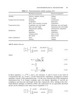
Figure 1.1 Bulk silicon micromachining: (a) isotropic etching; (b) anisotropic etching; (c) aniso-
tropic etching with buried etch-stop layer; (d) dielectric membrane released by back-side
bulk etching; (e) dopant dependent wet etching. (f) anisotropic dry etching. Reproduced from
C.L. Goldsmith, S. Eshelman and D. Dennston, 1998, ‘Performance of low loss RF MEMS
capacitive switches’, IEEE Microwave and Guided Wave Letters 8: 269 –271, by permission of
IEEE,
1998 IEEE
MICROFABRICATIONS FOR MEMS 7
used to realize micromechanical structures within the bulk of a single-crystal silicon wafer
by selectively removing (‘etching’) wafer material. The microstructures fabricated using
bulk micromachining may cover the thickness range from submicron to full wafer thick-
ness (200 to 500 µm) and the lateral size range from submicron to the lateral dimensions
of a full wafer.
For etching such thick silicon substrate, anisotropic wet etchants such as solutions
of potassium hydroxide (KOH), ethylenediamine pyrocatechol (EDP), tetramethylammo-
nium hydroxide (TMAH) and hydrazine-water are used. These etchants have different
etch rates in different crystal orientations of the silicon (Aeidel, 1987; Peterson, 1982).
Wet etching in most case is done from the back side of the wafer while the plasma-etching
is being applied to the front side. In recent years, a vertical-walled bulk micromachining
technique known as SCREAM (single-crystal reactive etching and metallization), which
is a combination of anisotropic and isotropic plasma etching, is used (Shaw, Zhang and
MacDonald, 1994). The etch process can be made selective by the use of dopants (heavily
doped regions etch slowly), or may even be halted electrochemically (e.g. etching stops
upon encountering a region of different polarity in a biased p–n junction). A region at
which wet etching tends to slow down or diminish is called an ‘etch-stop’. There are sev-
eral ways in which an etch-stop region can be created; doping-selective etching (DSE) and
bias-dependent DSE (Petersen, 1982; Aeidel, 1982; Shaw, Shang and Macdonald 1994).
Wet etching occurs by dipping substrate into an etching bath or spraying it with etchants
which may be acid or alkaline. Wet etching can either be isotropic etching or anisotropic
etching depending on the structure of the materials or the etchants used. If the material is
amorphous or polycrystalline, wet etching is always isotropic etching (Figure 1.1a). Dur-
ing isotropic etching (etchants used are acid solution), resist is always undercut, meaning
the deep etching is not practical for MEMS. Single-crystal silicon can be anisotropically
etched. The etching features are determined by the etching speed, which is dependent
on the crystal’s orientation. The etching slows down significantly at the (111) planes of
silicon, relative to other planes. With the chosen wafers with different crystal orientation,
different buck machined features can be achieved (Figures 1.1b and 1.1c). Most com-
mon etchants used for anisotropic etching of silicon include alkali hydroxide etchants
(KOH, NaOH, etc.), ammonium-based solutions {NH
4
OH, TMAH [(CH
3
)
4
NOH], etc.}
and EDP (ethylene diamine pyrocatechol, and water). By combining anisotropic etching
with boron implantation (P+ etch-stop), and electrochemical etch-stop technique, varied
silicon microstructures can be bulk machined (Figure 1.1).
Dry etching occurs through chemical or physical interaction between the ions in the
gas and the atoms of the substrate. Nonplasma, isotropic dry etching can be possible using
xenon difluoride or a mixture of interhalogen gases and provides very high selectivity for
aluminum, silicon dioxide, silicon nitride, photoresist, etc. The most common dry etch-
ing of bulk silicon are plasma etching and reactive ion etching (RIE) etching, where the
external energy in the form of RF powder drives chemical reactions in low-pressure reac-
tion chambers. A wide variety of chlorofluorocarbon gases, sulfur hexafluoride, bromine
compounds and oxygen are commonly used as reactants. The anisotropic dry etching
processes are widely used in MEMS because of the geometry flexibility and less chem-
ical contamination than in wet etching sometimes. Arbitrarily oriented features can be
etched deep into silicon using anisotropic dry etching (Figure 1.1f). Very deep silicon
microstructures can be obtained by the deep RIE (DRIE) dry etching (Bryzek, Peterson
and McCulley, 1994).
8 MEMS AND RF MEMS
With bulk-micromachined silicon microstructures, the wafer-bonding technique is nec-
essary for the assembled MEMS devices. Surface micromachining, however, can be used
to build the monolithic MEMS devices.
1.3.2 Surface micromachining of silicon
Surface micromachining does not shape the bulk silicon but instead builds structures on the
surface of the silicon by depositing thin films of ‘sacrificial layers’ and ‘structural layers’
and by removing eventually the sacrificial layers to release the mechanical structures
(Figure 1.2). The dimensions of these surface micromachined structures can be several
orders of magnitude smaller than bulk-micromachined structures. The prime advantage of
surface-micromachined structures is their easy integration with IC components, since the
wafer is also the working for IC elements. It should be noted that as miniaturization in
immensely increased by surface micromachining, the small mass structure involved may
be insufficient for a number of mechanical sensing and actuation applications.
Surface micromachining requires a compatible set of structural materials, sacrificial
materials and chemical etchants. The structural materials must possess the physical and
(1) (2)
(3) (4)
(5) (6)
Lithography
Deposition of
the structural layer
Development of
the sacrificial layer
Lithography
Patterning of
the structural layer
Removal of
the sacrificial layer
Polycrystalline
silicon
Mask
Final
structure
Substrate
Mask
Sacrificial layer
(silicon dioxide)
Figure 1.2 Processing steps of typical surface micromachining. Reproduced from G. Stix, 1992,
‘Trends in micromechanics: micron machinations’, Scientific American (November 1992): 72–80,
by permission of Scientific American
MICROFABRICATIONS FOR MEMS 9
chemical properties that are suitable for the desired application. In addition, they must have
satisfactory mechanical properties; e.g. high yield and fracture stresses, minimal creep and
fatigue and good wear resistance. The sacrificial materials must have good mechanical
properties to avoid device failure during fabrication. These properties include good adhe-
sion and low residual stresses in order to eliminate device failure by delamination and/or
cracking. The etchants to remove the sacrificial materials must have excellent etch selec-
tivity and they must be able to etch off the sacrificial materials without affecting the
structural ones. In addition the etchants must have proper viscosity and surface tension
characteristics. The common IC compatible materials used in surface micromachining
are: (1) polysilicon/Silicon dioxide; low-pressure chemical vapor deposition (LPCVD)
deposited polysilicon as the structural material and LPCVD deposited oxide as the sac-
rificial material. The oxide is readily dissolved in HF solution without the polysilicon
being affected. Together with this material system, silicon nitride is often used for elec-
trical insulation. (2) Polyimide/aluminum; in this case polyimide is the structural material
and aluminum is the sacrificial material. Acid-based etchants are used to dissolve the
aluminum sacrificial layer. (3) Silicon nitride/polysilicon; silicon nitride is used as the
structural material, whereas polysilicon is the sacrificial material. For this material sys-
tem, silicon anisotropic etchants such as KOH and EDP are used to dissolve polysilicon.
(4) Tungsten/silicon dioxide; CVD deposited tungsten is used as the structural material
with oxide as the sacrificial material. HF solution is used to remove the sacrificial oxide.
Other IC-compatible materials such as silicon carbide, diamond-like carbon, zinc oxide,
gold, etc. are also used.
Surface micromachining could also be performed using dry etching methods. Plasma
etching of the silicon substrate with SF
6
/O
2
-based and CF
4
/H
2
-based gas mixtures is
advantageous since high selectivities for photoresist, silicon dioxide and aluminum masks
can be achieved. However, when using plasma etching, a large undercut of the mask is
observed. This is due to the isotropic fluorine atom etching of silicon which is known to be
high compared with the vertical etch induced by ion bombardment. In contrast, reactive
ion etching of poly-Si using a chlorine/fluorine gas combination produces virtually no
undercut and almost vertical etch profiles when using photoresist as a masking material.
Thus, rectangular silicon patterns which are up to 30 mm deep can be formed using
chlorine/fluorine plasmas out of polysilicon films and the silicon wafer surface.
Silicon microstructures fabricated by surface micromachining are usually planar struc-
tures (or are two dimensional). Other techniques involving the use of thin-film structural
materials released by the removal of an underlying sacrificial layer have helped to extend
conventional surface micromachining into the third dimension. By connecting polysilicon
plates to the substrate and to each other with hinges, 3D micromechanical structures can
be assembled after release. Another approach to 3D structures used the conformal depo-
sition of polysilicon and sacrificial oxide films to fill deep trenches previously etched in
the silicon substrate.
1.3.3 Wafer bonding for MEMS
Silicon micromachining has limitations in forming complex 3D microstructures in a
monolithic format; multichip structures are then proposed for advanced MEMS, where
wafer-to-wafer bonding is critical in the formation (Stix, 1992).
10 MEMS AND RF MEMS
The wafer bonding for MEMS can be categorized into three major types: anodic bond-
ing, intermediate-layer assisted bonding and direct bonding.
1.3.3.1 Anodic bonding
Anodic bonding is also called field-assisted thermal bonding, electrostatic bonding, etc.
Anodic bonding is usually established between a sodium glass and silicon for MEMS.
For the anodic bonding, a cathode and an anode are attached to the glass (or silicon with
glass thin coating) and silicon wafer, respectively; voltages applied range from 200 V to
1000 V. At the same time, the anode is put on a heater providing the bonding temperature
around 180 to ∼500
◦
C (Figure 1.3). During the bonding, oxygen ions from the glass
migrate into the silicon, resulting in the formation of a silicon dioxide layer between
silicon wafer and glass wafer and form a strong and hermetic chemical bond.
The advantage of anodic bonding for MEMS is that the low temperature used can ensure
the metalization layer (aluminum) could withstand this temperature without degradation.
1.3.3.2 Intermediate-layer assisted bonding
This type of bonding for MEMS requires an intermediate layer, which can be metal,
polymer, solders, glasses, etc., to fulfill the bonding between wafers (Stix, 1992). One of
the earliest wafer bonding – eutectic bonding – utilized gold as the intermediate layer for
Si–Si bonding for pressure sensors (Ko, Suminto and Yeh, 1985). The Au–Si eutectic
bonding takes place at 363
◦
C, well below the critical temperature of the metallized
aluminium layer. But the stress generated during bonding was found to be significant and
introduced sensor drift (Ko, Suminto and Yeh, 1985).
Polymers as an intermediate layer for bonding prevail at very low temperature, reason-
able high strength, no metal ion presence and low stress because of the elastic property of
polymers, etc. Usually, UV photoresists such as polyimide, AZ-4000, SU-8, polymethyl-
methacrylate (PMMA), and other UV-curable cross-linked polymers (Madou, 1997). The
disadvantage is that the bonded device with polymer may not hold the hermetic sealing
performance owing to the relatively high permittivity of polymers.
Glasses with low melting temperature as the intermediate layer for the bonding is
also demonstrated, where a layer of glass frit is usually deposited on the silicon wafer.
The flatness of the deposited frit layer is critical to obtaining uniform, strong, low-stress
bonding. The screen printing of glass frit was used for pressure sensor bonding and
exhibits good performance (Ko, Suminto and Yeh, 1985).
Anode
(heater)
Cathode
Glass
V
+
−
Silicon
Figure 1.3 Anodic bonding
MICROFABRICATIONS FOR MEMS 11
Other materials are also being developed as the intermediate layer for bonding with
low temperature, high strength and low stress (Stix, 1992).
1.3.3.3 Direct bonding
Direct bonding is also called silicon fusion bonding, which is used for silicon–silicon
bonding. Direct bonding is based on a chemical reaction between OH groups present at the
surface of native silicon or grown oxides covering the wafers (Madou, 1997). The direct
bonding usually follows three steps: surface preparation, contacting and thermal annealing.
The surface preparation step involves cleaning the surfaces of the two wafers to form
a hydrate surface. The wafer surface should be mirror smooth, the roughness should be
no greater than 10
˚
A, and the bow of a 4-inch wafer should be less than 5 micron to
achieve the necessary flatness (Stix, 1992). Following this preparation, the wafers are
aligned and contacted in a cleanroom environment by gently pressing the two wafers at
the surface central point. The surface attraction of the two hydrated surfaces then brings
the intimate contact over the entire wafer surfaces. The final step in direct bonding is to
anneal the bonding from room temperature to 1200
◦
C. This annealing process increases
the bond strength by more than one order of magnitude at temperatures as high as 800 to
∼1200
◦
C. But high-temperature annealing is not allowed for the metallized wafers. The
direct bonding prevails in the high-strength bonding, and the devices’ dimensions could
be scaled down if direct bonding approaches are taken other than anodic bonding.
Some low-temperature direct bonding processes are to be further developed.
1.3.4 LIGA process
MEMS generally require complex microstructures that are thick and three-dimensional
(Larson, 1999). Therefore, many microfabrication technologies have been developed to
achieve high-aspect-ratio (height-to-width) and 3D devices. The LIGA process is one of
those microfabrications.
LIGA is a German acronym for Lithographie, Galvanoformung, Abformung (lithogra-
phy, galvanoforming, moulding). It was developed by the research Center Karlsruhe in
the early 1980s in Germany using X-ray lithography for mask exposure, galvanoforming
to form the metallic parts and moulding to produce microparts with plastic, metal, ceram-
ics, or their combinations (Fujita, 1996). A schematic diagram of the LIGA process is
shown in Figure 1.4. With the LIGA process, microstructures’ height can be up to hun-
dreds of microns to millimeter scale, while the lateral resolution is kept at the submicron
scale because of the advanced X-ray lithography. Various materials can be incorporated
into the LIGA process, allowing electric, magnetic, piezoelectric, optic and insulating
properties in sensors and actuators with a high-aspect ratio, which are not possible to
make with the silicon-based processes. Besides, by combining the sacrificial layer tech-
nique and LIGA process, advanced MEMS with moveable microstructures can be built
(Figure 1.5). However, the high production cost of LIGA process due to the fact that it
is not easy to access X-ray sources limits the application of LIGA. Another disadvantage
of the LIGA process relies on that fact that structures fabricated using LIGA are not
truly three-dimensional, because the third dimension is always in a straight feature. As
we know, complex thick 3D structures are necessary for some advanced MEMS, which
means other 3D microfabrication processes need to be developed for MEMS.