Tài liệu RF MEMS And Their Applications P2 docx
Bạn đang xem bản rút gọn của tài liệu. Xem và tải ngay bản đầy đủ của tài liệu tại đây (299.86 KB, 20 trang )
ELECTROMECHANICAL TRANSDUCERS
17
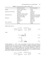
Table 1.2 Electromechanical mobility analogies [42]
Mechanical parameter Electrical parameter
Variable Velocity, angular velocity Voltage
Force, torque Current
Lumped network elements Damping Conductance
Compliance Inductance
Mass, mass moment of inertia Capacitance
Transmission lines Compliance per unit length Inductance per unit length
Mass per unit length Capacitance per unit length
Characteristic mobility Characteristic impedance
Immitances Mobility Impedance
Impedance Admittance
Clamped point Short circuit
Free point Open circuit
Source immitances Force Current
Velocity Voltage
ABCD matrix form as:
˙x
1
F
1
=
cos βx jZ
0
sin βx
j
Z
0
sin βx cos βx
˙x
2
F
2
(1.1)
where
Z
0
=
1
A
√
ρE
C
l
M
l
(1.2)
β =
ω
v
p
(1.3)
v
p
=
E
ρ
=
1
√
C
l
M
l
(1.4)
In these equations j =
√
−1, ˙x
1
and ˙x
2
are velocities, F
1
and F
2
forces at two ends of
a transmission line, Z
0
, β and v
p
are the characteristics impedance, propagation constant
and phase velocity of the transmission line, A is the cross-sectional area of the mechanical
transmission line, E its Young’s modulus, and ρ the density. Quantities C
l
and M
l
are
compliance and mass per unit length of the line, respectively. Now, looking at the elec-
tromechanical analogies in Johnson (1983), the expressions for an equivalent electrical
circuit can be obtained in the same form as Equation (1.1):
V
1
I
1
=
cos βx jZ
0
sin βx
j
Z
0
sin βx cos βx
V
2
I
2
(1.5)
18
MEMS AND RF MEMS
Table 1.3 Direct analogy of electrical and mechan-
ical domains
Mechanical quantity Electrical quantity
Force Voltage
Velocity Current
Displacement Charge
Momentum Magnetic flux linkage
Mass Inductance
Compliance Capacitance
Viscous damping Resistance
Source: Tilmans, 1996.
In Equation (1.5) V and I are the voltage and current on the transmission line (with
subscripts representing its ports). The other quantities in the matrix are also represented
by equivalent electrical parameters as:
Z
0
=
µ
ε
=
L
l
C
l
(1.6)
v
p
=
1
√
µε
=
1
√
L
l
C
l
(1.7)
In Equations (1.6) and (1.7) L
l
and C
l
represent the inductance and capacitance per unit
length of the line, and ε and µ are the permittivity and permeability of the transmission
medium.
Apart from the above mobility analogy a direct analogy is also followed at times to
obtain the equivalence between electrical and mechanical circuits. These result from the
similarity of integrodifferential equations governing electrical and mechanical components
(Tilmans, 1996). A brief list of these analogies are presented in Table 1.3.
An understanding of the underlying operational principle is essential in obtaining the
equivalent circuit of these transducers. A brief description of the operational principles
of some of these common transduction mechanisms used in electromechanical systems is
provided below.
1.4.1 Piezoelectric transducers
When subjected to mechanical stress, certain anisotropic crystalline materials generate
charge. This phenomenon, discovered in 1880 by Jaques and Pierre Curie, is known
as piezoelectricity. This effect is widely used in ultrasonic transducers. Lead zirconate
titanates (PZTs) are the most common ceramic materials used as piezoelectric transducers.
These crystals contain several randomly oriented domains if no electric potential is applied
during the fabrication process of the material. This results in little changes in the dipole
moment of such a material when a mechanical stress is applied. However, if the material
is subjected to an electric field during the cooling down process of its fabrication, these
domains will be aligned in the direction of the field. When external stress is applied
to such a material, the crystal lattices get distorted, causing changes in the domains
ELECTROMECHANICAL TRANSDUCERS
19
≈
f
p
C
0
C
1
L
1
jX
(c)
C
0
F
M
K
j
I
V
x
k
A
(d)
jX
F
I
V
x
(a)
f
s
f
p
Frequency
+
−
Reactance
jX
≈
(b)
Figure 1.7 Development of equivalent circuit of a piezoelectric transducer. Reproduced from
R.A. Johnson, 1983, Mechanical Filters in Electronics, Wiley Interscience, New York, by permis-
sion of Wiley,
1983 Wiley
and a variation in the charge distribution within the material. The converse effect of
producing strain is caused when these domains change shape by the application of an
electric field.
The development of the equivalent circuit for a piezoelectric bar is illustrated in
Figure 1.7 (Johnson, 1983). The bar vibrates in the direction (with force F and veloc-
ity ˙x) shown in the figure, by the application of an applied voltage (V ). The reactance
(j X) curve in Figure 1.7(b) can be obtained by ignoring higher order modes of vibration,
and the losses. One circuit configuration that results in similar reactance characteristics
is shown Figure 1.7(c). The electromechanical equivalent circuit can be constructed from
this, incorporates a gyrator with a resistance A and an inverter of reactance jκ in addi-
tion to the corresponding spring constant K and mass M. The gyrator represents the
nonreciprocal nature of the piezoelectric transducer. The inverter is required here since
the gyrator converts the parallel resonant circuit to a series circuit (Johnson, 1983). The
series combination of inverter and gyrator functions as a transformer with an imaginary
turns ratio jκ/A.
In general the piezoelectric transduction phenomenon is quadratic in nature, but may
be assumed to be linear for small deformations. The electromechanical coupling can then
be written as
Q = d
1
F (1.8)
x = d
2
V (1.9)
In these equations, d
1
and d
2
represent the piezoelectric charge modulus d in units 1
and 2, respectively. However, when both voltage and force are present, the following
piezoelectric coupling equations are used:
20
MEMS AND RF MEMS
Q = d
1
F + C
0
V (1.10)
x = d
2
V + C
m
F (1.11)
where C
0
is the free capacitance and C
m
the short-circuit compliance of the transducer.
The electromechanical coupling coefficient is another important nondimensional quantity
representing the performance of piezoelectric transducers. This is the ratio of mechanical
work available to the electrical energy stored in the transducer (Hom et al., 1994). The
coupling coefficient depends on the type of material, mode of stress and the polarization
of electric field. For a linear piezoelectric material, this is
η =
d
Sε
(1.12)
where d is a constant for piezoelectric material, S is the elastic compliance and ε is the
permittivity of the material.
PZT thin films have been developed using standard thin-film deposition techniques such
as sputtering, and physical or chemical vapor deposition. Their use in sensors and actuators
is inherently limited by the quality and repeatability of thin films obtained by these
techniques. Compared with bulk material processing techniques thin-film performance is
severely hampered by the surface properties where the film is deposited (Muralt, 2000).
Nonferroelectric AlN thin films are also explored, for sensor applications where voltage
output is required. However, PZT thin films are still preferred as actuators. Compared
with other electromechanical conversion schemes these require low voltage input but have
generally low electromechanical conversion efficiency.
1.4.2 Electrostrictive transducers
Electrostriction is the phenomenon of mechanical deformation of materials due to an
applied electric field. This is a fundamental phenomenon present to varying degrees in
all materials, and occurs as a result of the presence of polarizable atoms and molecules.
An applied electric field can distort the charge distribution within the material, resulting
in modifications to bond length, bond angle or electron distribution functions, which in
turn affects the macroscopic dimensions of the material.
The electric field E and the electric displacement D in a material are related by
D = ε
0
E + P (1.13)
where ε
0
is the free space permittivity (= 8.85 × 10
−12
Fm
−1
)andP is the polarization
of the material.
Using conservation of energy, the first law of thermodynamics for a electrically deform-
able material is (Hom et al., 1994):
dU =
T
ij
d
S
ij
+ E
k
dD
k
+ T dS(1.14)
In Equation (1.14), U is the internal energy for unit volume of the material, T is the stress
tensor, S is the infinitesimal strain tensor, T is the temperature and S is its entropy per
unit volume.
ELECTROMECHANICAL TRANSDUCERS
21
The elastic Gibbs function of a material is defined as
G = U −
T
ij
S
ij
−
1
2
ε
0
E
k
E
k
− TS (1.15)
Taking the derivative of Equation (1.15) and making use of Equation (1.13) we get:
dG = dU −
T
ij
d
S
ij
−
S
ij
d
T
ij
− E
k
(dD
k
− dP
k
) − T dS − S dT(1.16)
Substituting for dU from Equation (1.14), this simplifies to:
dG =−
S
ij
d
T
ij
+
1
2
E
k
P
k
− S dT(1.17)
The derivative of the Gibbs function G can be obtained using the chain rule as:
dG =
∂G
∂
T
ij
T
ij
+
∂G
∂P
k
P
k
+
∂G
∂T
T(1.18)
Comparing terms in Equation (1.17) and (1.18),
S
ij
=−
∂G
∂
T
ij
(1.19)
E
k
=
∂G
∂P
k
(1.20)
S =−
∂G
∂T
(1.21)
Assuming isotropic dielectric behavior, the Gibbs energy function for an elastic material
is given by (Hom et al., 1994):
G =−
1
2
s
P
ij kl
T
ij
T
kl
− Q
mnpq
T
mn
P
p
P
q
+
1
2k
|P| ln
1 +
|P|
P
s
1 −
|P|
P
s
−1
+ P
s
ln
1 −
|P|
P
s
2
(1.22)
The first term on the right-hand side describes the elastic behaviour of the material, s
P
being its elastic compliance at constant polarization. The electromechanical coupling is
denoted in the second term with the electrostrictive coefficients forming the matrix Q.The
last term is the dielectric behaviour of the material. P
s
is the spontaneous polarization,
and k is a material constant related to its dielectric constant. Since the material is assumed
to be isotropic, the magnitude of polarization is given as:
|P|=
P
k
P
k
(1.23)
22
MEMS AND RF MEMS
Temperature-dependent material coefficients used in Equation (1.22) such as s
P
, Q, P
s
and k are obtained from electrical and mechanical measurements.
Substituting Equation (1.22) into Equation (1.19) we get the constitutive equations for
electrostrictive materials as:
S
ij
= s
P
ij kl
T
kl
+ Q
ij mn
P
m
P
n
(1.24)
This shows the total strain in a material is the sum of elastic strain and polarization
induced strain. The second term on the right-hand side of Equation (1.24) represents the
electrostrictive effect. Thus this contribution is proportional to the square of the polariza-
tion in the material. This constitutive relation is valid even at large field intensities. Terms
in the matrix Q are the electrostriction coefficients and are obtained from measurements.
The phenomenon of electrostriction is very similar to piezoelectricity. One of the
fundamental difference between the two is the closeness of transition temperature of the
material to the operating temperatures. This accounts for the improved strain and hysteresis
properties for electrostrictive materials. However, a larger number of coefficients are
required to model electromechanical coupling for electrostriction. The polarization in
piezoelectric materials is spontaneous, while that in electrostrictive materials is field-
induced. The properties of electrostrictive materials are more temperature-dependent, and
the operating temperature range for these materials is narrower than for piezoelectrics
(Chen and Gururaja, 1997).
Material compositions based on lead magnesium niobate [Pb(Mg
0.33
,Nb
0.67
)O
3
(PMN)]
are commonly used as electrostrictive transducers. Their properties have been studied
extensively (Pilgrim, 2000). Practical thin-film transducers using this approach are yet to
be realized. However, polymeric thin-film materials with compliant graphite electrodes
are shown to have excellent electrostrictive properties (Pelrine, Kornbluh and Joseph,
1998). These materials are capable of efficient and fast response with high strains, good
actuation pressures (up to 1.9 MPa), and high specific energy densities. In this case, the
electrostriction phenomenon is not due to the molecular dipole realignment (Heydt et al.,
1998). In these silicone film actuators, the strain results from external forces caused by
electrostatic attraction of their graphite compliant electrodes. Although their mechanism is
electrostatics based, these actuators are shown to produce much larger effective actuation
pressure than conventional air-gap electrostatics with similar electric field.
1.4.3 Magnetostrictive transducers
Certain ferromagnetic materials show deformation when subjected to a magnetic field.
This phenomenon, commonly known as magnetostriction, is reversible and is also called
the Joule and Villari effect. In their demagnetized form, domains in a ferromagnetic
material are randomly oriented. However, when a magnetic field is applied these domains
gets oriented along the direction of the field. This orientation results in microscopic
forces between these domains resulting in the deformation of the material. By reciprocity,
mechanical deformation can cause orientation of domains, resulting in induction at the
macroscopic level (Rossi, 1988). The elongation is quadratically related to the induced
magnetic field and hence is strongly nonlinear.
Apart from the ferroelectric bar, the magnetostrictive transducer consists of a coil and
a magnet (Johnson, 1983). When a current I flows through the coil, the bar is deflected
ELECTROMECHANICAL TRANSDUCERS
23
jX
jX
N
F
I
S
f
p
F
M
K
I
V
x
(d)(c)
(a)
Frequency
+
−
Reactance
jX
(b)
x
f
p
f
s
∞
L
0
L
1
C
1
L
0
h : 1
Figure 1.8 Equivalent circuit for a magnetostrictive transducer. Reproduced from R.A. Johnson,
1983, Mechanical Filters in Electronics, Wiley Interscience, New York, by permission of Wiley,
1983 Wiley
in the direction shown with force F and velocity ˙x. The development of the equivalent
circuit of such a transducer is shown schematically in Figure 1.8. The reactance (j X)
diagram shown in Figure 1.8(b) is measured with no load. The pole and zero frequencies
in this curve correspond to parallel and series resonances of the system. It is not very
hard to obtain the component values of an LC circuit shown in Figure 1.8(c) which result
in the same pole and zero frequencies as with the system in Figure 1.8(a). Therefore
Figure 1.8(c) is an idealized electrical equivalent circuit for the transducer shown in
Figure 1.8(a). This is an idealized model as it does not take into consideration the losses
in the system.
It is now possible to translate this electrical equivalent circuit to the electromechanical
circuit shown in Figure 1.8(d). This has electrical and mechanical components (mass M
and spring K) connected with an electromechanical transformer. The turns ratio of this
transformer is decided by the amount of coupling, known as the electromechanical cou-
pling coefficient. This is defined as the ratio of the energy stored in the mechanical circuit
to the total input energy.
The electromechanical coupling for a magnetostrictive transducer shown in Figure 1.8(a)
relates the force at one end of the rod (the other end being constrained) to the current i in
the coil as (Rossi, 1988):
F =
g
EN
R
m
i(1.25)
where F is the magnetostrictive force, g
is the magnetostrictive strain modulus, E is the
Young’s modulus of the material, R
m
is the total reluctance of the magnetic circuit, and
N is the number of turns in the coil. The ratio on the right-hand side of Equation (1.25)
24
MEMS AND RF MEMS
is the electromechanical coupling. The same value for the coefficient relates the induced
voltage V at the terminals of the coil with the rate of change in displacement at the free
end of the bar:
V =
g
EN
R
m
˙x(1.26)
Ferrites, and metallic alloys such as Permalloy (45% Ni + 55% Fe), Alfer (13% Al +
87% Fe) and Alcofer (12% Al + 2% Co + 86% Fe) are some of the common materials
used in magnetostrictive transducers. Some of these materials can also be deposited as
thin films thus making it possible to fabricate microactuators and sensors with them.
Amorphous thin films such as TbFe
2
,Tb
0.3
Dy
0.7
Fe
2
and DyFe
2
have been reported
in the literature (Body, Reyne and Meunier, 1997). The realization of such thin films
is more process dependent than their bulk counterparts, as the preparation conditions
affect the homogeneity and growth process of the film as well as its stoichiometry. RF
magnetron sputtering of METGLAS
2605-SC ribbon with a chemical composition of
Fe
81
Si
3.5
B
13.5
C
2
on a GaAs substrate has been used in a pressure sensor with figure of
merit comparable with that of conventional piezoresistive strain gauges (Karl et al., 2000).
Microelectromechanical filters using this technology have not been reported so far in the
literature, but seem promising.
1.4.4 Electrostatic actuators
Electrostatic actuation is the most common type of electromechanical energy conversion
scheme in micromechanical systems. This is a typical example of an energy-storage trans-
ducer. Such transducers store energy when either mechanical or electrical work is done
on them (Crandall et al., 1968). Assuming that the device is lossless, this stored energy
is conserved and later converted to the other form of energy. The structure of this type
of transducer commonly consists of a capacitor arrangement, where one of the plates is
movable by the application of a bias voltage. This produces displacement, a mechanical
form of energy.
To derive an expression for the electromechanical coupling coefficient, let us first
consider a parallel plate capacitor. In Figure 1.9, the bottom plate is fixed, and the top one
is movable. The constitutive relations of this structure for voltage (V ) and force (F )are
given in terms of displacement (x) and charge (Q). These relations can be obtained either
analytically from electrostatics, or experimentally when a complicated system with various
losses has to be modeled. Assuming that there are no fringing fields, the capacitance of
this configuration at rest is widely known to be:
C
0
=
εA
d
0
(1.27)
However, when a voltage is applied across this system, the top plate moves towards the
other, resulting in a net gap
d = d
0
− x(1.28)
The capacitance with the plates at this new position is
C =
εA
d
=
εA
d
0
− x
= εA
d
0
1 −
x
d
0
−1
= C
0
1 −
x
d
0
−1
(1.29)