Học Actionscript 3.0 - p 24 pot
Bạn đang xem bản rút gọn của tài liệu. Xem và tải ngay bản đầy đủ của tài liệu tại đây (5.88 MB, 10 trang )
The Geometry Package
Chapter 8: Drawing with Vectors
209
For example, combinations of elements, such as scale and rotation, can be
applied at once, and matrices can even be used to achieve effects that are
otherwise not possible with individual properties, such as skewing.
You can also use matrices for more advanced operations such as determining
where a point ends up after an object has been transformed. In other words,
the point (10, 10) near the upper-left corner of a rectangle will not be at point
(10, 10) after a 90-degree rotation. The
Matrix class can tell you the new loca-
tion to which that point has moved, or even the change in location between
the new and original points.
The
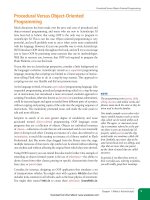
Matrix class provides a basic 3 × 3 matrix for use in several transfor-
mation processes. Its structure can be seen in Figure 8-15. Built-in
Matrix
properties
a and d affect scaling. Properties b and c will skew (or shear) an
object. The
tx and ty properties affect x and y location, respectively. Together,
elements
a, b, c, and d, affect rotation. The last three values in the matrix, u,
v, and w, are not used in ActionScript and can be ignored.
Table 8-1 shows the transformations possible with a matrix. The first column
shows the type of transformation, the second column lists related properties
and a simplified class method for accomplishing the goal (if one exists), and
the third column shows the values that must be adjusted, if you need to do
so manually. It is almost always more convenient to use existing methods,
or the
a, b, c, d, tx, and ty properties, but writing out the matrix explicitly
is useful when you want to make several changes at once. Finally, the last
column depicts a representative change in an object when the transformation
is applied.
Table 8-1. Matrix values and how they transform objects
Transformation Properties/Methods Matrix Result
Identity
Default matrix, null transformation
a, b, c, d, tx, ty
identity()
1,
0,
0,
0,
1,
0,
0
0
1
[
]
Translation
Changes position, x and y, respectively,
using pixels
tx, ty
translate(tx, ty)
1,
0,
0,
0,
1,
0,
tx
ty
1
[
]
Scale
Scales along the x and y axes, respectively,
using percent
a, d
scale(a, d)
sx,
0,
0,
0,
sy,
0,
0
0
1
[
]
Rotation
Rotates, using radians
a, b, c, d
rotate(q)
cos(q),
–sin(q),
0,
sin(q),
cos(q),
0,
0
0
1
[
]
a,
b,
u,
c,
d,
v,
tx
ty
w
[
]
Figure 8-15. Matrix properties
(continued)
Download from Wow! eBook <www.wowebook.com>
Part II: Graphics and Interaction
210
The Geometry Package
Table 8-1. Matrix values and how they transform objects
Transformation Properties/Methods Matrix Result
Skew (Shear)
Skews along the x and y axes, respec-
tively, using pixels
b, c
None. (See the
MatrixTransformer note in
the “Calculating changes in
points after transformations”
section.)
1,
tan(zy),
0,
tan(zx),
1,
0,
0
0
1
[
]
Skewing with matrices
To test this information, let’s use the Matrix class to do something you can’t
do with a built-in property or method—skew a display object. The following
script, found in the matrix_skew_1.fla source file, creates a rectangle with the
Graphics class and then skews it.
To start with, lines 1 through 7 create a translucent green rectangular sprite
with a 1-pixel black border and add it to the display list. The function span-
ning lines 9 through 10, originally discussed in Chapter 7, converts degrees to
radians for use with the
Matrix skewing code.
1 var rect:Sprite = new Sprite();
2 addChild(rect);
3 var g:Graphics = rect.graphics;
4 g.lineStyle(1, 0x000000);
5 g.beginFill(0x00FF00, 0.4);
6 g.drawRect(0, 0, 100, 50);
7 g.endFill();
8
9 function deg2rad(deg:Number):Number {
10 return deg * Math.PI / 180;
11 }
12
13 var matrix:Matrix = rect.transform.matrix;
14 matrix.c = Math.tan(deg2rad(20));
15 rect.transform.matrix = matrix;
Finally, lines 13 through 15 apply the skewing effect. Line 13 creates a matrix
based on the existing object’s matrix, by retrieving the value of the
matrix
property of the
transform object. This makes sure you are starting from any
current transformation, whatever that may be. That is, if an object has already
been skewed, starting with a default matrix (also called an identity matrix)
will effectively reset the prior skew with the new values.
Line 14 sets the
c property of the matrix, which skews along the x-axis using
the angle specified. It requires radians instead of degrees, so a value of 20
degrees is passed to the conversion function to get back the required radian
value. Finally, the matrix is applied to the object’s
matrix property in line 15.
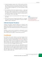
The result is seen in the top illustration in Figure 8-16.
c = 20
θ
c = –20
c = –20
x oset by
deltaTransformPoint()
Figure 8-16. A sprite skewed with the
Matrix class
(continued)
Download from Wow! eBook <www.wowebook.com>
The Geometry Package
Chapter 8: Drawing with Vectors
211
Note that the skew is applied to the bottom edge of the sprite. This is impor-
tant because if you wanted to give the sprite the appearance that it was
slanted right rather than left, you need to compensate with the correct angle.
Angles between 90 and 180 degrees and between 270 and 360 degrees will
slant an object to the right but it’s easier to use corresponding negative values.
The following change to the existing script (indicated in bold) is found in
matrix_skew_2.fla and uses –20 degrees instead of 20 degrees, and the result
appears in the middle illustration of Figure 8-16.
16 var matrix:Matrix = rect.transform.matrix;
17 matrix.c = Math.tan(deg2rad(-20));
18 rect.transform.matrix = matrix;
Calculating changes in points after transformations
The sprite slants to the right, but because horizontal skewing affects only
the bottom edge, the sprite now appears offset to the left. That is, we suc-
cessfully skewed the object –20 degrees, but it is no longer where we want it
to be. To compensate, we can use the occasionally life-saving methods that
calculate the change in a point’s location as a result of a transformation. We’ll
demonstrate this feature first. Putting aside the correction we’re seeking for
a mometnt, let’s trace the new position of a sprite point, as it exists after the
skew.
Let’s focus on the original location of the lower-left corner of the rectangle.
We knew that to be (0, 50) because the rectangle had a height of 50 and was
positioned at (0, 0) (per our
drawRect() instruction in line 6). Therefore, we
can pass a point of (0, 50) to the
transformPoint() method to see the new
value of that location:
19 trace(matrix.transformPoint(new Point(0, 50)));
The new point will trace as approximately (18, 50) because the prior point
(0, 50) has been skewed to the left. Calculating this change can require fairly
involved trigonometry, so this method is very handy.
If we stopped here, we could determine the difference between the two points
and change the location of the sprite accordingly. However, there’s already a
method that eliminates the need to calculate the offset. The
deltaTransform-
Point()
method determines the change in the before and after locations of a
point, rather than the absolute old and new locations.
We know from the prior trace that the lower-left corner of the rectangle
has moved approximately 18 points to the left, and did not move vertically.
Therefore, passing (0, 50) to the
deltaTransformPoint() method will return
a point that is approximately (–18, 50). All we need to do is use that infor-
mation to correct the location of the sprite. We can, therefore, stubtract the
x change in the point from the original x, and the sprite will be restored to
its original position. Add lines 16 and 17 to the ongoing example (as in the
matrix_skew_2.fla source file) and see the bottom illustration in Figure 8-16.
20 rect.x -= matrix.deltaTransformPoint(new Point(0, 50)).x;
N OT E
If you’re a Flash Professional user, check
out the timesaving
MatrixTransformer
class. It’s part of the
fl.motion pack-
age, added to Flash to support recreating
timeline animations with ActionScript.
This class makes matrix transfor-
mations even easier than the dedi-
cated methods of the
Matrix class. For
instance, it has getters and setters for
every matrix setting and both degrees
and radians are supported, eliminating
the need to convert angle values before
use.
Here’s an example of using the class to
skew the mc movie clip 20 degrees:
var matrix:Matrix = new Matrix();
MatrixTransformer.
setSkewX(matrix, 20);
mc.transform.matrix = matrix;
That’s easier than transforming points,
as described in the “Skewing with matri-
ces” discussion of this chapter. The class
can also automatically rotate a display
object around any point, rather than
just the object’s transformation point.
See the “Using the MatrixTransformer
Class” post at the companion website
for more information.
Download from Wow! eBook <www.wowebook.com>
Part II: Graphics and Interaction
212
The Geometry Package
Manipulating gradient fills and line styles
Now that you know a little bit about matrices, you can exert greater control
over gradient fills and line styles. The first time we introduced gradient fills,
we filled a rectangle with a radial gradient. The center of the fill did not
match the center of the object because we couldn’t control the scale of the
gradient. Similarly, the scale of the gradient applied to the line style was too
large, not revealing full red on the left or full black on the right.
Using matrices, you can control a number of attributes, including the width,
height, rotation, and translation of these fills and line styles. To simplify this
process for you, Adobe added the
createGradientBox() method to the Matrix
class. This method allows you to affect all of these properties with a single
method call, and accepts these parameters:
createGradientBox(width, height, rotation, tx, ty);
Let’s see how the optional addition of a matrix to the beginGradientFill()
method improves our gradient, by starting with the simplest use of the
createGradientBox() method. The following code is derived from the prior
radial gradient example and is found in the radial_gradient_2.fla source file.
We’ve created a matrix in line 10, and then used the
createGradientBox()
method in line 11 to set the size of the matrix to match the size of the sprite.
Finally, we added that matrix to the fill creation in line 12.
1 var canvas = new Sprite();
2 addChild(canvas);
3 var g:Graphics = canvas.graphics;
4
5 var gradType:String = GradientType.RADIAL;
6 var colors:Array = [0xFF0000, 0x000000];
7 var alphas:Array = [1, 1];
8 var ratios:Array = [0, 255];
9
10 var matrix:Matrix = new Matrix();
11 matrix.createGradientBox(100, 100, 0);
12 g.beginGradientFill(gradType, colors, alphas, ratios, matrix);
13
14 g.drawRect(0, 0, 100, 100);
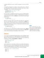
Figure 8-17 shows the original look of the gradient (top) and its appearance
after matching its size to that of the rectangle. After the transformation, the
radial gradient is now entirely visible.
By adding translation values to the method, you can also now reposition the
center of the gradient. For example, using 30 pixels for
tx and ty would place
the epicenter of the gradient in the lower-right corner of the rectangle, dem-
onstrated in the radial_gradient_3.fla source file.
15 var matrix:Matrix = new Matrix();
16 matrix.createGradientBox(100, 100, 0, 30, 30);
To demonstrate the rotation of a gradient, we’ll change the script in two
small ways. First, we’ll switch the gradient type from radial to linear so the
rotation is more noticeable (line 5). Then we’ll send a rotation value into
Figure 8-17. A radial gradient before (top)
and after (bottom) matrix transformations
Download from Wow! eBook <www.wowebook.com>
The Geometry Package
Chapter 8: Drawing with Vectors
213
the createGradientBox() method (line 11). The degree-to-radian conversion
function rounds out the changes in lines 16 through 18 of the following script.
Figure 8-18 shows before and after rotating a linear gradient 90 degrees. This
code can be found in the linear_gradient_matrix.fla source file.
17 var canvas = new Sprite();
18 addChild(canvas);
19 var g:Graphics = canvas.graphics;
20
21 var gradType:String = GradientType.LINEAR;
22 var colors:Array = [0xFF0000, 0x000000];
23 var alphas:Array = [1, 1];
24 var ratios:Array = [0, 255];
25
26 var matrix:Matrix = new Matrix();
27 matrix.createGradientBox(100, 100, deg2rad(90));
28 g.beginGradientFill(gradType, colors, alphas, ratios, matrix);
29
30 g.drawRect(0, 0, 100, 100);
31
32 function deg2rad(deg:Number):Number {
33 return deg * (Math.PI / 180);
34 }
Adjusting gradient line styles
The same matrix adjustment can improve the gradient line style example from
earlier in the chapter. The following example, from the line_style_ gradient_
matrix.fla source file, uses the changes indicated in bold to display the full
size of the gradient—exposing full red and full black at the left and right
sides, respectively. The result appears in Figure 8-19, which can be compared
with Figure 8-5 to see the change.
1 var canvas:Sprite = new Sprite();
2 addChild(canvas);
3 var g:Graphics = canvas.graphics;
4
5 canvas.x = canvas.y = 10;
6 g.lineStyle(20, 0x000000);
7
8 var gradType:String = GradientType.LINEAR;
9 var colors:Array = [0xFF0000, 0x000000];
10 var alphas:Array = [1, 1];
11 var ratios:Array = [0, 255];
12
13 var matrix:Matrix = new Matrix();
14 matrix.createGradientBox(200, 200, 0);
15
16 g.lineGradientStyle(gradType, colors, alphas, ratios, matrix);
17 g.drawRect(0, 0, 200, 200);
Adjusting bitmap line styles
So far, we’ve adjusted the size of gradients to improve their appearance in
fills and line styles. Now let’s look at using a matrix to translate the location
of a bitmap line style or fill. When a bitmap tiles, it initially tiles relative to
N OT E
The linear_gradient_matrix.fla source
file contains additional code to create a
second box with a gradient that is not
rotated. Comparing the boxes next to
each other, as seen in Figure 8-18, will
show the effect of the matrix manipula-
tion.
Figure 8-18. A linear gradient after (top)
and before (bottom) rotation with the
Matrix class
Figure 8-19. A gradient line style
transformed with a matrix to show the full
range of colors in the gradient. Compare
with Figure 8-5.
Download from Wow! eBook <www.wowebook.com>
Part II: Graphics and Interaction
214
The Geometry Package
a global positioning point. That is, point (0, 0) of your tile won’t necessar-
ily line up with point (0, 0) of your object. The following code, found in
line_style_bitmap_tiled_heart.fla, uses a heart tile to fill a 20-pixel line. The
initial result, shown in Figure 8-20, demonstrates what can happen when the
tile and object don’t initially line up properly.
1 var canvas:Sprite = new Sprite();
2 addChild(canvas);
3 var g:Graphics = canvas.graphics;
4
5 canvas.x = canvas.y = 10;
6 g.lineStyle(20, 0x000000);
7
8 g.lineBitmapStyle(new HeartTile(20, 19));
9 g.drawRect(0, 0, 200, 209);
However, we can use a matrix to translate the x and y coordinates of the bit-
map so that it better matches our shape. The following adjustments appear
in the line_style_bitmap_tiled_heart_matrix.fla source file. The changes to the
previous script add a matrix (line 9), use the
translate() method to move
the bitmap 10 pixels to the left and 9 pixels up, and then apply the matrix
when creating the line’s bitmap style (line 11). (To prevent this particular tile
from showing an extra pixel at the bottom, we also reduced the height of the
rectangle. Be prepared to fiddle with your values a bit, to achieve your goal.)
The result can be seen in Figure 8-21.
10 var matrix:Matrix = new Matrix();
11 matrix.translate(-10, -9);
12
13 g.lineBitmapStyle(new HeartTile(20, 19), matrix);
14 g.drawRect(0, 0, 200, 209);
Gradient Spread Method
For our last word on gradients, let’s talk about the available gradient spread
methods. Using these options, you can control the way a gradient behaves
when it fills an area larger than its own dimensions. In Flash Professional’s
Color panel this feature is called overflow (or flow in version CS5), but in
ActionScript it is called the spread method. The default behavior is extend
in the Color panel, which is called pad in ActionScript—specified by the
SpreadMethod.PAD constant. This setting continues the last color in the gradi-
ent throughout the remaining visible area to which the gradient is applied.
This can be seen in all prior figures depicting gradients, as well as in the first
illustration of Figure 8-22.
N OT E
The change in nomenclature for the gradient fill spread method was required because
overflow and extend both have important separate meanings in ActionScript.
Figure 8-20. Bitmap line style with no
transformation matrix
Figure 8-21. Bitmap line style corrected
with transformation matrix
Download from Wow! eBook <www.wowebook.com>
9-Slice Scaling
Chapter 8: Drawing with Vectors
215
The other two ActionScript options, SpreadMethod.REFLECT and SpreadMethod.
REPEAT
, share the same names and functionality with the Color panel. The
former reverses the colors as many times as is needed to occupy the available
space filled by the gradient, as if the gradient was held against a mirror. The
latter fills the visible area in a similar fashion but starts over at the first color
as if tiled. Figure 8-22 shows these effects in the middle and bottom illustra-
tions, respectively.
To control this feature, we must add another optional parameter to the
beg-
inGradientFill()
call. The following code is found in spread_method.fla,
and is based on the code from the linear_gradient_matrix.fla source file. The
changes in bold, reflect the gradient. Commented lines are included for test-
ing the pad and repeat options, as well. You can switch the comments to see
the varying results.
Remember that a gradient needs to spread only when it is smaller than the
canvas it is trying to fill. Therefore, this example reduces the width and height
of the gradient using the
createGradientBox() method to show the effect in
action. If both the gradient and rectangle were 100 × 100 pixels, no spreading
would occur.
1 var canvas:Sprite = new Sprite();
2 addChild(canvas);
3 var g:Graphics = canvas.graphics;
4
5 var gradType:String = GradientType.LINEAR;
6 var colors:Array = [0xFF0000, 0x000000];
7 var alphas:Array = [1, 1];
8 var ratios:Array = [0, 255];
9
10 var matrix:Matrix = new Matrix();
11 matrix.createGradientBox(50, 50, deg2rad(90), 0, 0);
12
13 //var spread:String = SpreadMethod.PAD;
14 var spread:String = SpreadMethod.REFLECT;
15 //var spread:String = SpreadMethod.REPEAT;
16 g.beginGradientFill(gradType, colors, alphas, ratios, matrix,
spread);
17
18 g.drawRect(0, 0, 100, 100);
19
20 function deg2rad(deg:Number):Number {
21 return deg * (Math.PI / 180);
22 }
9-Slice Scaling
Scaling vectors is usually a pleasure because the crispness of the vector art
isn’t lost when it’s resized. This is because the vectors are recalculated every
time an object is scaled. However, one of the downsides of this default behav-
ior is that certain visual characteristics, such as stroke weight and rounded
corners, can become distorted during scaling. This phenomenon can be seen
in the top two illustrations of Figure 8-23.
Figure 8-22. Gradient fill spread method
options pad (top), reflect (middle), and
repeat (bottom)
Download from Wow! eBook <www.wowebook.com>
Part II: Graphics and Interaction
216
9-Slice Scaling
To reduce distortion caused by scaling in many types of display objects, you
can use a feature called 9-slice scaling. This feature virtually slices a display
object into nine pieces and controls scaling of these pieces independently. A
typical grid of nine slices can be seen in Figure 8-23, marked with “9-slice
scaling enabled.” The four corners are not scaled. The top and bottom slices
between the corners are scaled only horizontally, the left and right slices
between the corners are scaled only vertically, and the center slice is scaled in
both directions.
To enable this feature using ActionScript, you must set the correspond-
ing
scale9grid property to a rectangle that, in essence, defines the object’s
center slice. ActionScript then extrapolates the corners and perimeter slices
by extending the sides of the virtual rectangle. The aforementioned “9-slice
scaling enabled” illustration in Figure 8-23 shows this by darkening the cen-
ter rectangle and outlining the slices with dashed lines. To demonstrate this
feature, the following exercise, found in the scale9.fla source file, will create a
sprite with rounded corners and then scale it using the mouse.
Lines 1 through 9 follow our familiar routine of creating a sprite, drawing vec-
tor assets, and positioning and adding the sprite to the display list. However,
there’s one new twist to this process. The
lineStyle() method in line 6 con-
tains an optional parameter we haven’t discussed. The third parameter tells
the method to give the line an alpha value of 100 percent. This parameter was
discussed in the Drawing Shapes section of the chapter when we overlapped
a 50-percent fill and a 50-percent line. (See the circle in Figure 8-1.) An alpha
value of 1 is the default behavior, but we need to include it here to add our
fourth parameter. (It’s not possible to vary the order in which parameters are
supplied to this method, so the first three must be present to use the fourth.)
The fourth parameter enables stroke hinting, which aligns strokes along
whole pixels, improving legibility. Specifically, this parameter reduces the
apparent loss of stroke thickness due to anti-aliasing and improves the look
of rounded corners, which is central to this exercise.
1 var canvas:Sprite = new Sprite();
2 canvas.x = canvas.y = 50;
3 addChild(canvas);
4
5 var g:Graphics = canvas.graphics;
6 g.lineStyle(1, 0x000000, 1, true);
7 g.beginFill(0xFFFF00, 0.5);
8 g.drawRoundRect(0, 0, 100, 50, 15);
9 g.endFill();
10
11 var slice9rect:Rectangle = new Rectangle(15, 15, 70, 20);
12 canvas.scale9Grid = slice9rect;
13
14 addEventListener(Event.ENTER_FRAME, onLoop, false, 0, true);
15 function onLoop(evt:Event):void {
16 canvas.width = Math.max(mouseX - canvas.x, 30);
17 canvas.height = Math.max(mouseY - canvas.y, 30);
18 }
original
scaled with distortion
9-slice scaling enabled
scaled without distortion
Figure 8-23. 9-Slice scaling reduces
distortion during scaling
N OT E
It is possible to slice a display object
into a different number of slices by
repositioning the slice-defining rectangle,
but unpredictable results may occur.
Download from Wow! eBook <www.wowebook.com>
Applied Examples
Chapter 8: Drawing with Vectors
217
Lines 11 and 12 create a rectangle that is inset from all four sides of the sprite
by 15 pixels, and sets the
scale9Grid property of the sprite to the specified
rectangle. An inset of 15 pixels is just enough to ensure that the rounded
corners of the rectangle are positioned in the four corners of the grid, thus
preventing scaling.
Finally, an event listener calls the
onLoop() function every enter frame, resiz-
ing the sprite based on the mouse location. Lines 16 and 17 set the width and
height, respectively, of the sprite to the mouse coordinates minus 50, which
are the
x and y values of the sprite assigned in line 2. So, if the mouse is at
point (150, 150), the sprite will have a size of 100 × 100.
One new element, introduced in lines 16 and 17, limits how small the rect-
angle can become. The
max() method of the Math class determines which of
the two values provided to it is larger and uses that value. Therefore, if the dis-
tance of the mouse from the sprite registration point’s x or y value is greater
than 30, that value is used. Conversely, if the mouse is closer than 30 pixels
to the sprite’s registration point, 30 will be used. This allows the rectangle to
scale but prevents it from getting any smaller than 30 × 30 pixels.
If you want to see a live comparison between using and not using 9-slice scal-
ing, add the bold lines in the following code to your script, or see the source
file, which already includes this code. Every time you click the mouse, the
feature toggles between on and off by alternately applying or removing the
rectangle to the sprite’s
scale9Grid property.
19 //switch between default and 9-slice scaling
20 function onLoop(evt:Event):void {
21 canvas.width = Math.max(mouseX - sp.x, 30);
22 canvas.height = Math.max(mouseY - sp.y, 30);
23 }
24
25 stage.addEventListener(MouseEvent.CLICK, onClick, false, 0, true);
26 function onClick(evt:Event):void {
27 if (canvas.scale9Grid) {
28 canvas.scale9Grid = null;
29 } else {
30 canvas.scale9Grid = slice9rect;
31 }
32 }
Applied Examples
Now let’s use much of what we’ve covered in this chapter in two applied
examples. In the first exercise, we’ll create the artwork for a basic color picker.
Then we’ll create a custom button tool that can serve as a lightweight, code-
only alternative to components. In both cases, let’s build the examples in
classes to practice using object-oriented programming.
N OT E
Remember that providing left-, top-,
right-, and bottom-edge coordinates does
not specify a Flash rectangle. Instead,
the x and y coordinates of the upper-left
corner, width, and height of the rect-
angle are specified. So, a rectangle that
insets 15 pixels from a 100 × 50-pixel
sprite, must start at the sprite’s point
15, 15, and have dimensions of 70 × 20
pixels.
P
u
s
h
Y
o
u
r
s
e
l
f
!
Download from Wow! eBook <www.wowebook.com>
Part II: Graphics and Interaction
218
Applied Examples
Starting a Color Picker
Let’s start by writing a class that will build the display portion of a simple
color picker. In the next chapter, we’ll show you how to retrieve values from
the picker using your mouse. To preview this exercise, test the color_picker_
graphics_example.fla source file, which simply instantiates the class we’re
about to discuss, and adds it to the display list.
The picker will contain two separate pieces: a color spectrum in vertical
blended stripes, and a transparent-to-black gradient overlay, as seen in Figure
8-24. The overlay will allow you to vary how much black is added to a color.
First we’ll create the color spectrum and add it to the display list. Then we’ll
create the transparent-to-black overlay and add it to the display list. Adding
it after the color spectrum gradient will position it on top. Because both
sprites will be added to the class, all you need to do is add an instance of the
finished class to the display list of your project and your color picker artwork
will be self-contained and ready for the functional enhancements planned in
Chapter 9.
Now take a look at the following code. Lines 1 through 10 cover the basic
syntax found in many classes. Line 1 defines the package, including a pack-
age location. This means that the
ColorPickerGraphics class will be found
inside a directory called color, which is inside learningactionscript3, which is
inside com.
Lines 3 through 6 import the necessary classes, line 8 defines the class, and
line 10 defines the constructor that will be executed immediately when the
class is instantiated. Note in line 8 that the class extends
MovieClip. This
means that this class will inherit the public and protected properties and
methods found in
MovieClip. It also means that we can add the class to the
display list as if it were a movie clip itself.
Our gradient method requires arrays for colors, alpha values, and color ratios,
as previously described. The colors array includes red, yellow, green, cyan,
blue, purple, and red again. The alphas array contains a 1 for every color,
rendering each step in the gradient at full alpha. The ratios array evenly dis-
tributes each color across the 0–255 span, without weighting any one color
over another.
The spectrum is next created and added to the display list in lines 18 through
20. The process is then repeated for the overlay. The overlay includes two
evenly distributed colors, black at 0 percent alpha, and black at 100 percent
alpha (lines 22 through 24). It’s then created and added to the display list.
We’ll explain the calls to
drawGradientBox(), in lines 18 and 26 when we
discuss the method. Review the following code and then we’ll look at the
method that creates the artwork.
Figure 8-24. Two layers of the color picker
N OT E
Creating the two layered gradients for
the picker requires the same code with
only minor variance in some of the set-
tings. Therefore, it makes sense to define
a method to handle the work without a
lot of repetition. This way, we can vary
the parameters sent to the method and
create multiple gradients with the same
code.
N OT E
The reverse domain naming convention
is discussed in Chapters 1 and 6.
N OT E
Because the artwork is created in the
constructor, and the data is passed to
the gradient method through param-
eters, there is no need for these values to
be stored in class properties.
Download from Wow! eBook <www.wowebook.com>