Beginning Game Programming (phần 8) docx
Bạn đang xem bản rút gọn của tài liệu. Xem và tải ngay bản đầy đủ của tài liệu tại đây (1.55 MB, 50 trang )
I consider the wheel complete, but I suppose the ‘‘star’’ pattern on the wheel might
cause some in the perfectionist crowd to pause. Never fear: it’s a simple matter to
switch back to Wireframe mode and nudge the vertices up to beat the rim of the
wheel into a semi-circular shape. You can manipulate vertices and lines directly in
Flat Shaded mode; often this is quite difficult, but I think this wheel is simple
enough that you can mange it. Just remember to hit A each time you want to select
a vertex, then hit M to move it, then drag it to a new location, and then hit A again
to select the next one. Working in 1-View mode is easier. (See Figure 13.36.)
While I’m at it, I think I’ll fine-tune the tire as well, as there are some weird jagged
edges there. You can do this if you want or you can just move on
The Frame
Well, after the experience of creating the wheel, the rest of the car will seem like
child’s play. As you can see from the tutorial on creating the wheel, it’s easy to
330 Chapter 13
n
Creating Your Own 3D Models with Anim8or
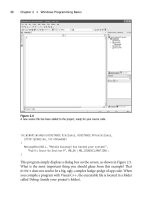
Figure 13.36
Fine-tuning the geometry of the rim part of the wheel
keep adding more and more detail to a 3D model. However, if you have the time
and willingness, the results are always better when you add more details to each
mesh. Now let’s work on the frame, which will be simplistic in comparison. Go
ahead and add a new object for the car frame.
Tip
When you need to add a new object in Anim8or, open the Object menu and select New.
The important thing to remember when working on meshes is that they can be
scaled in the scene, so don’t worry about making everything to scale right now (in
other words, don’t worry about comparing the car frame to the wheel mesh).
Creating the Main Car Frame
First, add a rectangular solid to the scene and then convert it to a mesh using the
Build menu. The actual shape is not all that important right away because you can
use the Object/Point Edit mode to grab a side of the mesh and drag it to the
dimensions you want. Try to make the car frame look like the one in Figure 13.37.
Creating the Car Mode l 331
Figure 13.37
The main car frame is basically just a rectangular solid.
Tip
Whenever you manipulate the vertices, lines, or faces of a mesh to resize it, you can use the Build,
Join Solids menu option to redefine the mesh at the new size.
Add a second cube (or rectangular solid from the Build menu) and convert it to a
mesh. Resize the mesh using the Object/Point Edit mode—select the lines of a
face and move them out so that the mesh sits on top of the car frame. The mesh
should be about half the length of the frame, as this is the cab or roof of the car.
See Figure 13.38.
Once you have completed the car’s body, click the Drag Select icon and drag a
selection box around both mesh objects to select both of them. Open the Build
menu and select Group. The car body will now be treated as a single mesh.
Now open up the Materials toolbar (Options, Materials) and double-click the
first empty material. Change the ambient color to an attractive car-paint color.
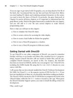
332 Chapter 13
n
Creating Your Own 3D Models with Anim8or
Figure 13.38
The cabin/roof mesh has been added on top of the car frame.
Add a few more materials in like manner using several different colors. You will
be able to change the car’s color by applying any one of these materials to the car
body. Choose a material that you like and apply it to the two car body pieces. See
Figure 13.39.
Tip
If you haven’t done so yet, save your work now!
The Windows
The windows are the same for both the front and rear of the car, while a second
set of windows is used for the two sides of the car. Figure 13.40 shows the
windows used for the front and rear. We won’t be modeling doors now, but that
would be a great project to try after the basic car is done. The windshield has a light
gray-colored material applied to it, and is made up of just a simple rectangular
Creating the Car Mode l 333
Figure 13.39
The car body has been grouped and a colorful material applied.
solid that has been stretched into a thin rectangle. It will take some tweaking of the
windows to get them to fit in the body of the car during scene-building time, at
which point you can return to the windows and edit them. Switching back and
forth between objects and scenes is something you will do frequently.
The side windows are similar to, but not quite as large as, the front and rear
windows. You can copy the front window, create a new object, and paste it into
the new object space, then resize as needed during scene time. Figure 13.41 shows
the side windows.
The Headlights and Taillights
All that remains to be done at this point are the headlights and taillights. Of
course, you could add a lot more detail to this car. I will leave that up to you
(though I may add some new objects to this car and use it in a game at some point
in the near future, because I’ve become quite fond of it!).
334 Chapter 13
n
Creating Your Own 3D Models with Anim8or
Figure 13.40
The front and rear windows shar e a mesh and are ready to be installed.
The Headlight
Add a new object to the works and then create a new rectangular solid (or a cube)
that is rather thin but otherwise square in width and height. Open the Build
menu and select Convert to Mesh. Go back into the Build menu and select
Subdivide Faces to bring up the Smooth Parameters dialog. Type in 0.25 for the
tension value and click OK.
Repeat this step again to subdivide the headlight again by 0.25. You can try to
subdivide it again if you want even more smoothness to try to get that headlight
bulb shape. See Figure 13.42.
Now the headlight needs a slightly glowing material so that it will look like a real
headlight. It won’t shoot out a beam of light, but it will at least appear to glow
(using the Emissive property), which is a pretty good effect. Figure 13.43 shows
the material properties for the headlight.
Creating the Car Mode l 335
Figure 13.41
The side windows also share a mesh.
The Taillight
Now for the taillights. The process will be similar to that of the headlights, except
that the taillight needs to be square rather than round. Add a new object and add
a rectangular solid or a cube that is very thin but equally wide and high, like you
did for the headlight.
Next, select the object and convert it to a mesh using the Build menu. Open the
Build menu again and select Subdivide Faces to bring up the Smooth Parameters
dialog.
First, subdivide the taillight by 1.0. That will turn it into four solids but will retain
the basic shape. Next, subdivide it again by 0.25. This will give it a basically square
shape, but with rounded corners.
Create a material that is a deep red with an emissive value of 0.4; this way, it
will have a faint glow to it. Figure 13.44 shows the material properties for the
336 Chapter 13
n
Creating Your Own 3D Models with Anim8or
Figure 13.42
The headlight is created by subdividing a simple rectangular solid.
Creating the Car Mode l 337
Figure 13.43
The headlight material is white with a faintly illuminated yellow color.
Figure 13.44
The taillight material is a faint ly illuminated red color.
taillight. (Of course, you won’t see the actual colors in the black-and-white
screenshots.)
Figure 13.45 shows the finished taillight with the material applied to it.
Creating a Scene
Generally, you will want to create an entire model as a single object rather than
assembling a model from component parts created as individual meshes in
Anim8or’s Object Edit mode. However, it is very convenient to be able to edit the
meshes on their own without other parts of the model getting in the way, and it is
a simple matter to copy and paste meshes from one object into another. If you
were going to create a complex scene with more than just the single car, you
would want to combine it all into a single object so that it would be possible to
control the car as a whole. As a learning experience, though, I think it was easier
338 Chapter 13
n
Creating Your Own 3D Models with Anim8or
Figure 13.45
The complete taillight mesh with an illuminated red color.
to construct the car using the Scene Editor. You can export the car to a 3ds max
(.3ds) file from the Scene Editor, so this works well for creating models to be used
in a game.
Figure 13.46 shows the completed Hummer in the Scene Editor. The most
surprising thing about this model is that no textures were used; only materials
were used to give the car texture and color! What I’m going to do at this point is
show you how to add one of the objects to the scene and then leave it up to you to
assemble the car, factory style! Just remember the things you have learned in the
chapter so far: how to select, rotate, move, and scale objects. If scaling is a big
problem and all of your pieces are way out of kilter, I recommend you switch to
the Object Editor and change the scale of the objects at the source rather than
inside the Scene Editor. Not only is this much easier, but it ensures that your car
model will be uniform and consistent.
Creating a Scene 339
Figure 13.46
The completed Hummer is ready for a test drive.
First, open the Mode menu and select Scene. This puts you in Scene Edit mode.
Next, open the Build menu and select Add Object. You can select an object from
the Object Selector dialog. If the objects are all unnamed, you may want to switch
back to Object Edit mode and give each part of the car an identifying name. You
can do this while in Object Edit mode by opening the Settings dialog and
choosing Object, which will bring up a dialog that will allow you to name the
object. This is especially helpful when you are working on a complex scene with
dozens or even hundreds of objects!
Caution
If you get completely stuck while trying to build the car in this chapter, you can always load the
Anim8or file off the CD-ROM. Just be sure to clear the read-only property of the car.an8 file. It is
located in \sources\chapter13.
What You Have Learned
This chapter provided a tutorial on how to use Anim8or to create your own 3D
models. Here are the key points:
n You learned that Anim8or is a free 3D modeling program.
n You learned where to find Anim8or on the Web.
n You learned how to use viewports to change the view of a scene.
n You learned how to create stock primitive objects.
n You learned how to manipulate points, lines, and faces in a mesh.
n You learned how to create objects and insert them into a scene.
n You learned enough information to create a 3D car from scratch.
340 Chapter 13
n
Creating Your Own 3D Models with Anim8or
Review Questions
The following questions will help you to determine whether you have retained
the information presented in this chapter.
1. What is a mesh?
2. How many editing modes are there in Anim8or?
3. How do you convert a stock primitive into a mesh?
4. How to you go into Object/Point Edit mode to manipulate a mesh?
5. How do you bring up the Materials toolbar?
Review Questions 341
On Your Own
The following exercises will help you to think outside the box and push your
limits, helping you to retain the information you’ve been shown.
Exercise 1. The Hummer model is still very primitive, but it was a good example
of what you can do. See if you can improve the model by adding more detail to
the car body itself. Add front and rear bumpers, a hood that rises toward the
windshield (rather than being flat), and passenger doors.
Exercise 2. This model would really benefit from the use of textures rather than
just simple materials. Try to locate the texture for a wheel on the Web and apply
it to the Hummer’s wheels. If you can’t find a wheel texture, then consider
creating one yourself using a graphic editor like The Gimp, which is available for
free from . Textures can be applied from the Material Editor
dialog.
342 Chapter 13
n
Creating Your Own 3D Models with Anim8or
Working with 3D
Model Files
This chapter is a natural follow-up to Chapter 13, in which you learned how to
create a 3D model from scratch using Anim8or. This chapter takes it a step
further, teaching you how to convert that model into a format that can be loaded
into your own Direct3D programs. You will learn how to convert, load, and
render the Hummer car model that was created in Chapter 13.
Here is what you will learn in this chapter:
n How to convert a 3DS file to .X.
n How to optimize a model file.
n How to load a model file into memory.
n How to manipulate and draw a model on the screen.
343
chapter 14
Converting 3D Files
The most difficult part of getting a model into your game is converting it to
the Direct3D format, which has an extension of .X. Without some guidance,
you face the hit-or-miss task of searching the Web for 3D file converters, and
you never know how reliable or up-to-date these programs are. Although
Direct3D can read the .X file format, it does not set up the materials and
textures for you; this is something that you will have to learn to do yourself.
Fortunately, it is possible to read the material and texture counts from the
mesh object after an .X file has been loaded , which can then be used to
iterate through the materials and textures and then render the .X model. I’ll
go over this relatively painless code shortly. First, let’s talk about converting
files.
Converting 3DS to .X
There is a program called conv3ds.exe that was once included in the DirectX SDK
up through version 8.1, but was dropped in version 9.0. It is true that Discreet no
longer supports the 3DS format, and that the MAX format is now the standard,
but most software products still work with 3DS files, including Anim8or. The
conv3ds.exe tool is very convenient for Anim8or users because Anim8or exports
to the 3DS format, so I have included it on the CD-ROM.
Tip
The conv3ds.exe program is included on the book’s CD-ROM in \software\conv3ds.
Using the conv3ds Utility
I recommend you copy conv3ds.exe to your \Windows or \WINNT folder on
your primary drive partition so it will be available to any command prompt. Or
you can just add it to the system path by opening Control Panel, System, then
clicking the Advanced tab, and then clicking the Environment Variables button.
Here you can edit the path to add any folder you want.
Type conv3ds.exe to see the list of options. The most common usage is this:
conv3ds -m file.3ds
This converts a 3ds file to .X and combines all meshes into a single mesh, which
optimizes the file. If the conversion succeeds, nothing is displayed on the screen.
344 Chapter 14
n
Working with 3D Model Files
If you want to see some details about the conversion as it takes place, you can add
the following verbose option:
conv3ds -m -v1 file.3ds
The -v1 option will display the meshes that are being converted over and saved in the
new .X file. The Hummer model is quite huge compared to the cube in Chapter 11,
forinstance,soinordertousethesamebasicrenderingoptionsinthecodeyouare
used to, it is helpful to reduce the scale of the car model. This isn’t totally necessary;
you could just zoom out with the camera to an appropriate distance so that the car
model will show up, but it’s more convenient to rescale the model as it is converted.
So, let’s convert over the car.3ds file that was exported from Anim8or. The option
to alter the scale of the model is -s, and you give it a scale value:
conv3ds -m -v1 -s0.05 car.3ds
Tip
You can export an entire scene in Anim8or using the Scene, Export option. To export a single mesh
(in Object/Edit mode), use the Object, Export option.
That command will produce a Hummer model that is only five percent of the
original size, without losing any details. The scaling problem is just due to the size
of the model that I created in Anim8or. When you create your own 3D models,
you’ll want to load them into your game to see how they scale compared to the
rest of the game. It’s better to adjust scale of the original model in your modeling
program, but in this example, I wanted to also show you an option for changing
the scale when the file is converted.
Using the MeshView Utility
After you have converted a 3ds max file to a Direct3D file, you can load it in your
program. But first, it’s a good idea to use the MeshView program (included with
the DirectX SDK). The MeshView program is located in \DX90SDK\Utilities.
You can also run it from the Start menu. Go to Programs, Microsoft DirectX 9.0
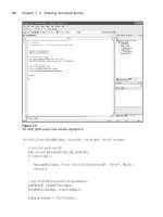
SDK, DirectX Utilities, Mesh Viewer. Figure 14.1 shows the Mesh Viewer with
our Hummer from Chapter 13 loaded.
Mesh Viewer includes a lot of advanced options that will help identify problems
with a mesh, such as incorrect texture coordinates, materials, or normals (used
for lighting). Take a look at the status bar on the bottom-right of the Mesh
Converting 3D Files 345
Viewer window and you’ll see some information about your .X file. The two
values on the right side show the total number of triangles (faces) and vertices,
respectively. Remember that a mesh created with triangle strips will share ver-
tices, which is why this model has many more faces than vertices. According to
Mesh Viewer, our Hummer model has 17,016 polygons. Not bad for your first
attempt at 3D modeling!
Optimizing the Model
What we’re really interested in is the optimization features of Mesh Viewer. If
you think about it, this Hummer model has been through quite a bit and is not
necessarily the most efficient model in the world. First, it was exported from
Anim8or’s Scene Editor into a .3ds file. Then it was converted to a .X file using
the conv3ds utility.
346 Chapter 14
n
Working with 3D Model Files
Figure 14.1
The Hummer created in the last chapter has been converted to .X and loaded into Mesh Viewer.
Try optimizing the model using some of the features in Mesh Viewer. Figure 14.2
shows one good option that will try to reduce the polygon count of the model. Go
into the MeshOps menu, select Optimize, Compact. Before you do this, take a
look at the vertex count at the bottom-right corner of the window. The Hummer
model that was converted to .X has 13,916 vertices. Pay attention to that number
as you perform various optimizations; it will go down to reflect a model that has
been cleaned up.
Triangle Removal Optimization
Another good optimization is in MeshOps, Weld Vertices (see Figure 14.3). This
will combine vertices and rebuild the triangle strip for every two polygons (faces)
that share two vertices. If you’ll recall, this car model was constructed from many
Converting 3D Files 347
Figure 14.2
Optimizing the mesh can reduce the number of vertices and fix any problems with the faces.
individual parts, so most of it is comprised of adjacent polygons that are not
joined. Welding the vertices in this way helps to clean up the model quite a bit.
I recommend selecting the first three options and leaving the rest alone, unless you
are a 3D guru (in which case, why are you reading this book?). Figure 14.4 shows
the Weld Vertices dialog box.
Here are the options I selected:
n Remove Back To Back Triangles. This will eliminate duplicate triangles
that are not needed.
n Regenerate Adjacency. This will rebuild the triangle strip structure after
the vertices have been welded (or shared).
348 Chapter 14
n
Working with 3D Model Files
Figure 14.3
Welding the vertices will rebuild the triangle strip and improve the mesh.
n Partial Weld Vertices. This will generate additional polygons, if necessary,
to share common vertices not at the line ends.
When you click Apply or OK, the vertex optimization will begin. Whoa—take a
look at Figure 14.5. Ten percent of the vertices have been eliminated by this single
optimization, from 13,916 vertices down to 11,308!
Weld Vertices Optimization
If your model is fairly simple and does not need to be manipulated at run time,
then you can try the next optimization. Go back into MeshOps and select Weld
Vertices again. This time, check just the Weld All Vertices option. Click Apply to
see the result. Very complex models probably should not have this optimization
done to them; then again, it’s worth a try to see if the model still looks correct in
your game. According to Figure 14.6, this results in 25 percent more vertices
removed from the model. Altogether, about 35 percent of the vertices have been
combined without any apparent change in the model.
Saving the File
Be sure to save the file before you close the Mesh Viewer utility! Go to File, Save
Mesh As to bring up the Save As dialog box (see Figure 14.7). You can type in the
filename and also the file type, which will be one of the following:
n Text
Converting 3D Files 349
Figure 14.4
The Weld Vertices dialog box
n Binary
n Binary Compressed
This is interesting because you can at least prevent someone from opening your
model files in a text editor by saving them in the binary compressed format—it’s
not much protection, but it does prevent players from modifying your model files
without a binary .X reader. Binary compressed .X files are about one-tenth the file
size of the text format (on average), so your game installation will be much smaller.
Just be sure to keep your source models in the standard 3ds or .X format.
350 Chapter 14
n
Working with 3D Model Files
Figure 14.5
The Weld Vertices optimization has eliminated 10 percent of the vertices.
Loading and Rendering a Model File
The only thing left to do is learn how to load a model from an .X file into your
Direct3D program and render it on the screen! Are you ready? I said, are you
ready!? Let’s get to it, then.
Loading and Rendering a Model File 351
Figure 14.6
Weld All Vertices optimization eliminates 25 percent more vertices.
Figure 14.7
Saving the model file
Loading an .X File
Direct3D provides a function to create a mesh out of an .X file that is loaded, and
that makes it very simple to read in any model file into your own games (because
you now have the ability to convert a 3DS file to .X).
Let’s learn how to load a model. Instead of starting off with 100 percent theory,
I’m going to show you complete, working code so you’ll be able to understand it
better when you get to the project I’ll give you later in the chapter.
Defining the MODEL Structure
First, we need a new struct to deal with model files that are to be loaded from disk:
struct MODEL
{
LPD3DXMESH mesh;
D3DMATERIAL9* materials;
LPDIRECT3DTEXTURE9* textures;
DWORD material_count;
};
Some programmers and modelers prefer to call them ‘‘mesh files,’’ but I submit
that ‘‘mesh’’ does not properly describe the contents of a typical 3D model file
(such as car.X). These files contain meshes, materials, and a lot of data types and
animation instructions. So to call it just a mesh file is incorrect. I much prefer
‘‘model,’’ hence the name of the struct above.
The
MODEL struct contains the primary objects needed to load and render a model
file. First, you have the mesh. If your original model file contained many meshes/
objects, then it should have been condensed down to a single mesh by the
conv3ds utility. Otherwise, the mesh here might represent multiple meshes
(which the .X file format supports).
Next, there is a
D3DMATERIAL9 pointer variable that will be loaded with an array
of materials defined in the model file.
LPDIRECT3DTEXTURE9 should already be
familiar to you after working with sprites, so no surprises here, except that a
model may contain multiple textures. These textures are not stored in the model
file itself, but in separate bitmap files, and the texture filenames are stored in the
model file.
Finally, there is a member variable that holds the number of materials in the
model, which is used during rendering. There may be many materials in a model,
352 Chapter 14
n
Working with 3D Model Files
but not every one is required to have a texture. However, a texture must be
defined within a material. Hence, we have a
material_count variable, but there is
no need to keep track of the number of textures.
Loading the Mesh
The key to loading a model file resides in the D3DXLoadMeshFromX function:
HRESULT WINAPI D3DXLoadMeshFromX(
LPCTSTR
pFilename
,
DWORD
Options
,
LPDIRECT3DDEVICE9
pDevice
,
LPD3DXBUFFER *
ppAdjacency
,
LPD3DXBUFFER *
ppMaterials
,
LPD3DXBUFFER *
ppEffectInstances
,
DWORD *
pNumMaterials
,
LPD3DXMESH *
ppMesh
);
The parameters for this function are filled with either defaults (in one form or
another) or NULLs, with key parameters being the filename, Direct3D device,
material buffer, material count, and mesh object. First, you need a material buffer
to load the materials into:
LPD3DXBUFFER matbuffer;
Let’s also assume that a pointer to the MODEL struct has already been created:
MODEL *model = (MODEL*)malloc(sizeof(MODEL));
The model struct is allocated in memory and returned by the LoadModel function
(which I’ll cover in a moment). Then you can read the model file and load the
materials and meshes at the same time. Here is sample code that calls this function:
result = D3DXLoadMeshFromX(
filename, //filename
D3DXMESH_SYSTEMMEM, //mesh options
d3ddev, //Direct3D device
NULL, //adjacency buffer
&matbuffer, //material buffer
NULL, //special effects
&model->material_count, //number of materials
&model->mesh); //resulting mesh
Loading and Rendering a Model File 353
Loading the Materials/Textures
The materials are stored in the material buffer, but they need to be converted into
Direct3D materials and textures before the model can be rendered. You are
familiar with the texture object, but the material object,
LPD3DXMATERIAL,isnew.
Here is how you copy the materials and textures out of the material buffer and
into individual material and texture arrays. First, let’s create the arrays:
D3DXMATERIAL* d3dxMaterials = (LPD3DXMATERIAL)matbuffer->GetBufferPointer();
model->materials = new D3DMATERIAL9[model->material_count];
model->textures = new LPDIRECT3DTEXTURE9[model->material_count];
The next step is to iterate through the materials and grab them out of the material
buffer. For each material, the ambient color is set and the texture is loaded into the
texture object. As these are dynamically allocated arrays, a model is limited only by
available memory and the ability of your video card to render it. You could have a
model with millions of faces, each with a different material.
for(i=0; i<model->material_count; i ++)
{
//grab the material
model->materials[i] = d3dxMaterials[i].MatD3D;
//set ambient color for material
model->materials[i].Ambient = model->materials[i].Diffuse;
model->textures[i] = NULL;
if( d3dxMaterials[i].pTextureFilename != NULL &&
lstrlen(d3dxMaterials[i].pTextureFilename) > 0 )
{
//load texture file specified in .X file
result = D3DXCreateTextureFromFile(d3ddev,
d3dxMaterials[i].pTextureFilename,
&model->textures[i]);
}
}
Rendering a Complete Model
Drawing the model is a piece of cake after it has been loaded. I’ll admit, the code to
load a model is not exactly easy to understand until you’ve walked through it line
by line a few times. The rendering code is much easier, and should be quite
understandable, because you have used the
DrawPrimitive function already.
354 Chapter 14
n
Working with 3D Model Files