Network+ 2005 In Depth (P4) ppt
Bạn đang xem bản rút gọn của tài liệu. Xem và tải ngay bản đầy đủ của tài liệu tại đây (844.32 KB, 30 trang )
This page intentionally left blank
Transmission Basics
and Networking
Media
Chapter 3
After reading this chapter and completing the exercises, you will be able to:
■ Explain basic data transmission concepts, including full duplexing,
attenuation, and noise
■ Describe the physical characteristics of coaxial cable, STP, UTP, and
fiber-optic media
■ Compare the benefits and limitations of different networking media
■ Identify the best practices for cabling buildings and work areas
■ Specify the characteristics of popular wireless transmission methods,
including 802.11, infrared, and Bluetooth
J
ust as highways and streets provide the foundation for automobile travel, networking media
provide the physical foundation of data transmission. Media are the physical or atmospheric
paths that signals follow. The first networks transmitted data over thick, heavy coaxial cables.
Today, data is commonly transmitted over a newer type of cable—one that resembles tele-
phone cords, with their flexible outsides and twisted copper wire insides. For long-distance net-
work connections, fiber-optic cable is preferred. And more and more, organizations are sending
signals through the atmosphere to form wireless networks. Because networks are always evolv-
ing and demanding greater speed, versatility, and reliability, networking media change rapidly.
Network problems often occur at or below the Physical layer. Therefore, understanding the
characteristics of various networking media is critical to designing and troubleshooting net-
works. You also need to know how data is transmitted over the media. This chapter discusses
network media and the details of data transmission. You’ll learn what it takes to make data
transmission dependable and how to correct some common transmission problems.
Transmission Basics
In data networking, the term transmit means to issue signals to the network medium. Trans-
mission refers to either the process of transmitting or the progress of signals after they have
been transmitted. In other words, you could say, “My NIC transmitted a message, but because
the network is slow, the transmission took 10 seconds to reach the server.”
Long ago, people transmitted information across distances via smoke or fire signals. Needless
to say, many different methods of data transmission have evolved since that time. The trans-
mission techniques in use on today’s networks are complex and varied. In the following sec-
tions, you will learn about some fundamental characteristics that define today’s data
transmission. In later chapters, you will learn about more subtle and specific differences between
types of data transmission.
Analog and Digital Signaling
One important characteristic of data transmission is the type of signaling involved. On a data
network, information can be transmitted via one of two signaling methods: analog or digital.
Both types of signals are generated by electrical current, the pressure of which is measured in
volts. The strength of an electrical signal is directly proportional to its voltage. Thus, when net-
work engineers talk about the strength of an analog or digital signal, they often refer to the
signal’s voltage.
The essential difference between analog and digital signals is the way voltage creates the sig-
nal. In analog signals, voltage varies continuously and appears as a wavy line when graphed over
time, as shown in Figure 3-1. Your speech, a siren, and live music are all examples of analog
waves.
Chapter 3 65
TRANSMISSION BASICS
FIGURE 3-1 An example of an analog signal
An analog signal, like other waveforms, is characterized by four fundamental properties: ampli-
tude, frequency, wavelength, and phase. A wave’s amplitude is a measure of its strength at any
given point in time. On a wave graph, the amplitude is the height of the wave at any point in
time. In Figure 3-1, for example, the wave has an amplitude of 5 volts at .25 seconds, an
amplitude of 0 volts at .5 seconds, and an amplitude of -5 volts at .75 seconds.
Whereas amplitude indicates an analog wave’s strength, frequency is the number of times that
a wave’s amplitude cycles from its starting point, through its highest amplitude and its lowest
amplitude, and back to its starting point over a fixed period of time. Frequency is expressed in
cycles per second, or hertz (Hz), named after German physicist Heinrich Hertz, who experi-
mented with electromagnetic waves in the late nineteenth century. For example, in Figure 3-1
the wave cycles to its highest then lowest amplitude and returns to its starting point once in
1 second. Thus, the frequency of that wave would be 1 cycle per second, or 1 Hz—which, as
it turns out, is an extremely low frequency.
Frequencies used to convey speech over telephone wires fall in the 300 to 3300 Hz range.
Humans can hear frequencies between 20 and 20,000 Hz. An FM radio station may use a fre-
quency between 850,000 Hz (or 850 KHz) and 108,000,000 Hz (or 108 MHz) to transmit its
signal through the air. You will learn more about radio frequencies used in networking later in
this chapter.
The distance between corresponding points on a wave’s cycle is called its wavelength.Wave-
lengths can be expressed in meters or feet. A wave’s wavelength is inversely proportional to its
frequency. In other words, the higher the frequency, the shorter the wavelength. For example,
a radiowave with a frequency of 1,000,000 cycles per second (1 MHz) has a wavelength of 300
meters, while a wave with a frequency of 2,000,000 Hz (2 MHz) has a wavelength of 150
meters.
The term phase refers to the progress of a wave over time in relationship to a fixed point. Sup-
pose two separate waves have identical amplitudes and frequencies. If one wave starts at its low-
est amplitude at the same time the second wave starts at its highest amplitude, these waves will
have different phases. More precisely, they will be 180 degrees out of phase (using the standard
assignment of 360 degrees to one complete wave). Had the second wave also started at its low-
est amplitude, the two waves would be in phase. Figure 3-2 illustrates waves with identical
amplitudes and frequencies whose phases are 90 degrees apart.
One benefit to analog signals is that, because they are more variable than digital signals, they
can convey greater subtleties with less energy. For example, think of the difference between your
voice and the digital voice of a digital answering machine. The digital voice has a poorer qual-
ity than your own voice—that is, it sounds “like a machine.” It can’t convey the subtle changes
in inflection that you expect in a human voice. Only very high-quality digital signals—for
example, those used to record music on compact discs—can achieve such accuracy.
66 Chapter 3
TRANSMISSION BASICS AND NETWORKING MEDIA
FIGURE 3-2 Waves with a 90-degree phase difference
However, because voltage is varied and imprecise in analog signals, analog transmission is
more susceptible to transmission flaws such as noise, or any type of interference that may
degrade a signal, than digital signals. If you have tried to listen to AM radio on a stormy night,
you have probably heard the crackle and static of noise affecting the signal.
Now contrast the analog signals pictured in Figures 3-1 and 3-2 to a digital signal, as shown
in Figure 3-3. Digital signals are composed of pulses of precise, positive voltages and zero
voltages. A pulse of positive voltage represents a 1. A pulse of zero voltage (in other words, the
lack of any voltage) represents a 0. The use of 1s and 0s to represent information is character-
istic of a binary system. Every pulse in the digital signal is called a binary digit, or bit.A bit
can have only one of two possible values: 1 or 0. Eight bits together form a byte.In
broad terms, one byte carries one piece of information. For example, the byte “01111001”
means “121” on a digital network.
Chapter 3 67
TRANSMISSION BASICS
FIGURE 3-3 An example of a digital signal
FIGURE 3-4 Components of a byte
Computers read and write information—for example, program instructions, routing informa-
tion, and network addresses—in bits and bytes. When a number is represented in binary form
(for example, “01111001”), each bit position, or placeholder, in the number represents a spe-
cific multiple of 2. Because a byte contains eight bits, it has eight placeholders. When count-
ing placeholders in a byte, you move from right to left. The placeholder farthest to the right is
known as the zero position, the one to its left is in the first position, and so on. The place-
holder farthest to the left is in the seventh position, as shown in Figure 3-4.
To find the decimal value of a bit, you multiply the 1 or 0 (whichever the bit is set to) by 2
x
,
where x equals the bit’s position. For example, the 1 or 0 in the zero position must be multi-
plied by 2 to the 0 power, or 2
0
, to determine its value. Any number (other than zero) raised
to the power of 0 has a value of 1. Thus, if the zero-position bit is 1, it represents a value of 1
x2
0
, or 1 x 1, which equals 1. If a 0 is in the zero position, its value equals 0 x 2
0
, or 0 x 1,
which equals 0. In every position, if a bit is 0, that position represents a decimal number of 0.
To convert a byte to a decimal number, determine the value represented by each bit, then add
those values together. If a bit in the byte is 1 (in other words, if it’s “on”), the bit’s numerical
equivalent in the coding scheme is added to the total. If a bit is 0, that position has no value
and nothing is added to the total. For example, the byte 11111111 equals: 1x2
7
+ 1x2
6
+ 1x2
5
+ 1x2
4
+ 1x2
3
+ 1x2
2
+ 1x2
1
+ 1x2
0
, or 128 + 64 + 32 + 16 + 8 + 4 + 2 + 1. Its decimal equiva-
lent, then, is 255. In another example, the byte 00100100 equals: 0x2
7
+ 0x2
6
+ 1x2
5
+ 0x2
4
+
0x2
3
+ 1x2
2
+ 0x2
1
+ 0x2
0
, or 0 + 0 + 32 + 0 + 0 + 4 + 0 + 0. Its decimal equivalent, then, is 36.
Figure 3-4 illustrates placeholders in a byte, the exponential multiplier for each position, and
the different decimal values that are represented by a 1 in each position.
To convert a decimal number to a byte, you reverse this process. For example, the decimal num-
ber 8 equals 2
3
, which means a single “on” bit would be indicated in the fourth bit position as
follows: 00001000. In another example, the decimal number 9 equals 8 + 1, or 2
3
+2
0
, and would
be represented by the binary number 00001001.
The binary numbering scheme may be used with more than eight positions. However, in the
digital world, bytes form the building blocks for messages, and bytes always include eight posi-
tions. In a data signal, multiple bytes are combined to form a message. If you were to peek at
the 1s and 0s used to transmit an entire e-mail message, for example, you might see millions
of zeros and ones passing by. A computer can quickly translate these binary numbers into codes,
such as ASCII or JPEG, that express letters, numbers, and pictures.
Converting between decimal and binary numbers can be done by hand, as shown previously,
or by using a scientific calculator, such as the one available with the Windows XP operating
system. Take, for example, the number 131. To convert it to a binary number:
1. On a Windows XP computer, click Start, point to All Programs, point to Acces-
sories, and then click Calculator.
2. Click View, and then click Scientific. Make sure that the Dec option button is selected.
3. Type 131, and then click the Bin option button. The binary equivalent of the number
131, 10000011, appears in the display window.
4. Close the Calculator window.
You can reverse this process to convert a binary number to a decimal number.
Because digital transmission involves sending and receiving only a pattern of 1s and 0s, repre-
sented by precise pulses, it is more reliable than analog transmission, which relies on variable
waves. In addition, noise affects digital transmission less severely. On the other hand, digital
transmission requires many pulses to transmit the same amount of information that an analog
68 Chapter 3
TRANSMISSION BASICS AND NETWORKING MEDIA
signal can transmit with a single wave. Nevertheless, the high reliability of digital transmission
makes this extra signaling worthwhile. In the end, digital transmission is more efficient than
analog transmission because it results in fewer errors and, therefore, requires less overhead to
compensate for errors.
Overhead is a term used by networking professionals to describe the nondata information that
must accompany data for a signal to be properly routed and interpreted by the network. For
example, the Data Link layer header and trailer, the Network layer addressing information,
and the Transport layer flow control information added to a piece of data in order to send it
over the network are all part of the transmission’s overhead.
It is important to understand that in both the analog and digital worlds, a variety of signaling
techniques are used. For each technique, standards dictate what type of transmitter, commu-
nications channel, and receiver should be used. For example, the type of transmitter (NIC) used
for computers on a LAN and the way in which this transmitter manipulates electric current to
produce signals is different from the transmitter and signaling techniques used with a satellite
link. While not all signaling methods are covered in this book, you will learn about the most
common methods used for data networking.
Data Modulation
Data relies almost exclusively on digital transmission. However, in some cases the type of con-
nection your network uses may be capable of handling only analog signals. For example, tele-
phone lines are designed to carry analog signals. If you dial into an ISP’s network to surf the
Internet, the data signals issued by your computer must be converted into analog form before
they get to the phone line. Later, they must be converted back into digital form when they
arrive at the ISP’s access server. A modem accomplishes this translation. The word modem
reflects this device’s function as a modulator/demodulator—that is, it modulates digital signals
into analog signals at the transmitting end, then demodulates analog signals into digital sig-
nals at the receiving end.
Data modulation is a technology used to modify analog signals to make them suitable for car-
rying data over a communication path. In modulation, a simple wave, called a carrier wave, is
combined with another analog signal to produce a unique signal that gets transmitted from
one node to another. The carrier wave has preset properties (including frequency, amplitude,
and phase). Its purpose is to help convey information; in other words, it is only a messenger.
Another signal, known as the information or data wave, is added to the carrier wave. When
the information wave is added, it modifies one property of the carrier wave (for example, the
frequency, amplitude, or phase). The result is a new, blended signal that contains properties of
both the carrier wave and added data. When the signal reaches its destination, the receiver
separates the data from the carrier wave.
Modulation can be used to make a signal conform to a specific pathway, as in the case of FM
(frequency modulation) radio, in which the data must travel along a particular frequency. In
frequency modulation, the frequency of the carrier signal is modified by the application of the
data signal. In AM (amplitude modulation), the amplitude of the carrier signal is modified by
Chapter 3 69
TRANSMISSION BASICS
NET+
1.6
the application of the data signal. Modulation may also be used to issue multiple signals to the
same communications channel and prevent the signals from interfering with one another. Fig-
ure 3-5 depicts an unaltered carrier wave, a data wave, and the combined wave as modified
through frequency modulation. Later in this book you will learn about networking technolo-
gies, such as DSL, that make use of modulation.
70 Chapter 3
TRANSMISSION BASICS AND NETWORKING MEDIA
NET+
1.6
FIGURE 3-5 A carrier wave modified through frequency modulation
Transmission Direction
Data transmission, whether analog or digital, may also be characterized by the direction in
which the signals travel over the media.
Simplex, Half-Duplex, and Duplex
In cases in which signals may travel in only one direction, the transmission is considered sim-
plex. An example of simplex communication is a football coach calling out orders to his team
through a megaphone. In this example, the coach’s voice is the signal, and it travels in only
one direction—away from the megaphone’s mouthpiece and toward the team. Simplex is
sometimes called one-way, or unidirectional, communication.
In half-duplex transmission, signals may travel in both directions over a medium but in only
one direction at a time. Half-duplex systems contain only one channel for communication, and
that channel must be shared for multiple nodes to exchange information. For example, an apart-
ment’s intercom system that requires you to press a “talk” button to allow your voice to be trans-
mitted over the wire uses half-duplex transmission. If you visit a friend’s apartment building,
you press the “talk” button to send your voice signals to his apartment. When your friend
responds, he presses the “talk” button in his apartment to send his voice signal in the opposite
direction over the wire to the speaker in the lobby where you wait. If you press the “talk” but-
ton while he’s talking, you will not be able to hear his voice transmission. In a similar manner,
some networks operate with only half-duplex capability.
When signals are free to travel in both directions over a medium simultaneously, the trans-
mission is considered full-duplex. Full-duplex may also be called bidirectional transmission or,
sometimes, simply duplex. When you call a friend on the telephone, your connection is an
example of a full-duplex transmission, because your voice signals can be transmitted to your
friend at the same time your friend’s voice signals are transmitted in the opposite direction to
you. In other words, both of you can talk and hear each other simultaneously.
Figure 3-6 compares simplex, half-duplex, and full-duplex transmissions.
Chapter 3 71
TRANSMISSION BASICS
FIGURE 3-6 Simplex, half-duplex, and full-duplex transmission
Full-duplex transmission is also used on data networks. For example, modern Ethernet net-
works are capable of full-duplex. In this situation, full-duplex transmission uses multiple chan-
nels on the same medium. A channel is a distinct communication path between nodes, much
as a lane is a distinct transportation path on a freeway. Channels may be separated either log-
ically or physically. You will learn about logically separate channels in the next section. An
example of physically separate channels occurs when one wire within a network cable is used
for transmission while another wire is used for reception. In this example, each separate wire
in the medium allows half-duplex transmission. When combined in a cable, they form a
medium that provides full-duplex transmission. Full-duplex capability increases the speed
with which data can travel over a network. In some cases—for example, telephone service over
the Internet—full-duplex data networks are a requirement.
Many network devices, such as modems and NICs, allow you to specify whether the device
should use half- or full-duplex communication. It’s important to know what type of transmis-
sion a network supports before installing network devices on that network. If you configure a
computer’s NIC to use full-duplex while the rest of the network is using half-duplex, for
example, that computer will not be able to communicate on the network.
Multiplexing
A form of transmission that allows multiple signals to travel simultaneously over one medium
is known as multiplexing. To carry multiple signals, the medium’s channel is logically sepa-
rated into multiple smaller channels, or subchannels. Many different types of multiplexing are
available and the type used in any given situation depends on what the media, transmission,
and reception equipment can handle. For each type of multiplexing, a device that can combine
many signals on a channel, a multiplexer (mux), is required at the sending end of the channel.
At the receiving end, a demultiplexer (demux) separates the combined signals and regenerates
them in their original form.
Multiplexing is commonly used on networks to increase the amount of data that can be trans-
mitted in a given time span. One type of multiplexing, TDM (time division multiplexing),
divides a channel into multiple intervals of time, or time slots. It then assigns a separate time
slot to every node on the network and, in that time slot, carries data from that node. For exam-
ple, if five stations are connected to a network over one wire, five different time slots are estab-
lished in the communications channel. Workstation A may be assigned time slot 1, workstation
B time slot 2, workstation C time slot 3, and so on. Time slots are reserved for their designated
nodes regardless of whether the node has data to transmit. If a node does not have data to
send, nothing is sent during its time slot. This arrangement can be inefficient if some nodes
on the network rarely send data. Figure 3-7 shows a simple TDM model.
Statistical multiplexing is similar to time division multiplexing, but rather than assigning a
separate slot to each node in succession, the transmitter assigns slots to nodes according to pri-
ority and need. This method is more efficient than TDM, because in statistical multiplexing
72 Chapter 3
TRANSMISSION BASICS AND NETWORKING MEDIA
FIGURE 3-7 Time division multiplexing
time slots are unlikely to remain empty. To begin with, in statistical multiplexing, as in TDM,
each node is assigned one time slot. However, if a node doesn’t use its time slot, statistical mul-
tiplexing devices recognize that and assign its slot to another node that needs to send data.
The contention for slots may be arbitrated according to use or priority or even more sophisti-
cated factors, depending on the network. Most importantly, statistical multiplexing maximizes
available bandwidth on a network. Figure 3-8 depicts a simple statistical multiplexing system.
Chapter 3 73
TRANSMISSION BASICS
FIGURE 3-8 Statistical multiplexing
WDM (wavelength division multiplexing) is a technology used with fiber-optic cable. In
fiber-optic transmission, data is represented as pulses of light, rather than pulses of electric
current. WDM enables one fiber-optic connection to carry multiple light signals simultane-
ously. Using WDM, a single fiber can transmit as many as 20 million telephone conversations
at one time. WDM can work over any type of fiber-optic cable.
In the first step of WDM, a beam of light is divided into up to 40 different carrier waves, each
with a different wavelength (and therefore, a different color). Each wavelength represents a sep-
arate transmission channel capable of transmitting up to 10 Gbps. Before transmission, each
carrier wave is modulated with a different data signal. Then, through a very narrow beam of
light, lasers issue the separate, modulated waves to a multiplexer. The multiplexer combines all
of the waves, in the same way that a prism can accept light beams of different wavelengths and
concentrate them into a single beam of white light. Next, another laser issues this multiplexed
beam to a strand of fiber within a fiber-optic cable. The fiber carries the multiplexed signals to
a receiver, which is connected to a demultiplexer. The demultiplexer acts as a prism to separate
the combined signals according to their different wavelengths (or colors). Then, the separate
waves are sent to their destinations on the network. If the signal risks losing strength between
the multiplexer and demultiplexer, an amplifier might be used to boost it. Figure 3-9 illustrates
WDM transmission.
FIGURE 3-9 Wavelength division multiplexing
The form of WDM used on most modern fiber-optic networks is DWDM (dense wave divi-
sion multiplexing). In DWDM, a single fiber in a fiber-optic cable can carry between 80 and
160 channels. It achieves this increased capacity because it uses more wavelengths for signaling.
In other words, there is less separation between the usable carrier waves in DWDM than there is
in the original form of WDM. Because of its extraordinary capacity, DWDM is typically used
on high-bandwidth or long-distance WAN links, such as the connection between a large ISP
and its (even larger) network service provider.
Relationships Between Nodes
So far you have learned about two important characteristics of data transmission: the type of
signaling (analog or digital) and the direction in which the signal travels (simplex, half-duplex,
full-duplex, or multiplex). Another important characteristic is the number of senders and
receivers, as well as the relationship between them. In general, data communications may
involve a single transmitter with one or more receivers, or multiple transmitters with one or
more receivers. The remainder of this section introduces the most common relationships
between transmitters and receivers.
When a data transmission involves only one transmitter and one receiver, it is considered a
point-to-point transmission. An office building in Dallas exchanging data with another office
in St. Louis over a WAN connection is an example of point-to-point transmission. In this
case, the sender only transmits data that is intended to be used by a specific receiver. By con-
trast, broadcast transmission involves one transmitter and multiple receivers. For example, a
TV station indiscriminately transmitting a signal from its tower to thousands of homes with
TV antennas uses broadcast transmission. A broadcast transmission sends data to any and all
receivers, without regard for which receiver can use it. Broadcast transmissions are frequently
used on networks because they are simple and quick. They are used to identify certain nodes,
to send data to certain nodes (even though every node is capable of picking up the transmit-
ted data, only the destination node will actually do it), and to send announcements to all
nodes. Another example of network broadcast transmission is sending video signals to multi-
ple viewers on a network. When used over the Web, this type of broadcast transmission is called
Webcasting. Figure 3-10 contrasts point-to-point and broadcast transmissions.
Throughput and Bandwidth
The data transmission characteristic most frequently discussed and analyzed by networking pro-
fessionals is throughput. Throughput is the measure of how much data is transmitted during
a given period of time. It may also be called capacity or bandwidth (though as you will learn,
bandwidth is technically different from throughput). Throughput is commonly expressed as a
quantity of bits transmitted per second, with prefixes used to designate different throughput
amounts. For example, the prefix “kilo” combined with the word “bit” (as in “kilobit”) indicates
1000 bits per second. Rather than talking about a throughput of 1000 bits per second, you typ-
ically say the throughput was 1 kilobit per second (1 Kbps). Table 3-1 summarizes the termi-
nology and abbreviations used when discussing different throughput amounts. As an example,
74 Chapter 3
TRANSMISSION BASICS AND NETWORKING MEDIA
a typical modem connecting a home PC to the Internet would probably be rated for a maxi-
mum throughput of 56.6 Kbps. A fast LAN might transport up to 10 Gbps of data. Contem-
porary networks commonly achieve throughputs of 10 Mbps, 100 Mbps, or 1 Gbps.
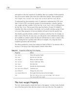
Table 3-1 Throughput measures
Quantity Prefix Complete Example Abbreviation
1 bit per second n/a 1 bit per second bps
1000 bits per second kilo 1 kilobit per second Kbps
1,000,000 bits per second mega 1 megabit per second Mbps
1,000,000,000 bits per second giga 1 gigabit per second Gbps
1,000,000,000,000 bits per second tera 1 terabit per second Tbps
Chapter 3 75
TRANSMISSION BASICS
FIGURE 3-10 Point-to-point versus broadcast transmission
Be careful not to confuse bits and bytes when discussing throughput. Although data
storage quantities are typically expressed in multiples of bytes, data transmission
quantities (in other words, throughput) are more commonly expressed in multiples of
bits per second. When representing different data quantities, a small “b” represents
NOTE
Often, the term “bandwidth” is used interchangeably with throughput, and in fact, this may be
the case on the Network+ certification exam. Bandwidth and throughput are similar concepts,
but strictly speaking, bandwidth is a measure of the difference between the highest and low-
est frequencies that a medium can transmit. This range of frequencies, which is expressed in
Hz, is directly related to throughput. For example, if the FCC told you that you could trans-
mit a radio signal between 870 and 880 MHz, your allotted bandwidth (literally, the width of
your frequency band) would be 10 MHz.
Baseband and Broadband
Baseband is a transmission form in which (typically) digital signals are sent through direct cur-
rent (DC) pulses applied to the wire. This direct current requires exclusive use of the wire’s
capacity. As a result, baseband systems can transmit only one signal, or one channel, at a time.
Every device on a baseband system shares the same channel. When one node is transmitting
data on a baseband system, all other nodes on the network must wait for that transmission to
end before they can send data. Baseband transmission supports half-duplexing, which means
that computers can both send and receive information on the same length of wire. In some
cases, baseband also supports full duplexing.
Ethernet is an example of a baseband system found on many LANs. In Ethernet, each device
on a network can transmit over the wire—but only one device at a time. For example, if you
want to save a file to the server, your NIC submits your request to use the wire; if no other
device is using the wire to transmit data at that time, your workstation can go ahead. If the
wire is in use, your workstation must wait and try again later. Of course, this retrying process
happens so quickly that you don’t even notice the wait.
Broadband is a form of transmission in which signals are modulated as radiofrequency (RF)
analog waves that use different frequency ranges. Unlike baseband, broadband technology
does not encode information as digital pulses.
As you may know, broadband transmission is used to bring cable TV to your home. Your cable
TV connection can carry at least 25 times as much data as a typical baseband system (like
Ethernet) carries, including many different broadcast frequencies on different channels. In
traditional broadband systems, signals travel in only one direction—toward the user. To allow
users to send data as well, cable systems allot a separate channel space for the user’s transmis-
sion and use amplifiers that can separate data the user issues from data the network transmits.
Broadband transmission is generally more expensive than baseband transmission because of
the extra hardware involved. On the other hand, broadband systems can span longer distances
than baseband.
76 Chapter 3
TRANSMISSION BASICS AND NETWORKING MEDIA
bits, while a capital “B” represents bytes. To put this into context, a modem may trans-
mit data at 56.6 Kbps (kilobits per second); a data file may be 56 KB (kilobytes) in
size. Another difference between data storage and data throughput measures is that
in data storage the prefix kilo means “2 to the 10
th
power,” or “1024,” not “1000.”
In the field of networking, some terms have more than one meaning, depending on their con-
text. “Broadband” is one of those terms. The “broadband” described in this chapter is the
transmission system that carries RF signals across multiple channels on a coaxial cable, as used
by cable TV. This definition was the original meaning of broadband. However, broadband has
evolved to mean any of several different network types that use digital signaling to transmit
data at very high transmission rates.
Transmission Flaws
Both analog and digital signals are susceptible to degradation between the time they are issued
by a transmitter and the time they are received. One of the most common transmission flaws
affecting data signals is noise.
Noise
As you learned earlier, noise is any undesirable influence that may degrade or distort a signal.
Many different types of noise may affect transmission. A common source of noise is EMI
(electromagnetic interference), or waves that emanate from electrical devices or cables carry-
ing electricity. Motors, power lines, televisions, copiers, fluorescent lights, manufacturing
machinery, and other sources of electrical activity (including a severe thunderstorm) can cause
EMI. One type of EMI is RFI (radiofrequency interference), or electromagnetic interfer-
ence caused by radiowaves. (Often, you’ll see EMI referred to as EMI/RFI.) Strong broadcast
signals from radio or TV towers can generate RFI. When EMI noise affects analog signals,
this distortion can result in the incorrect transmission of data, just as if static prevented you
from hearing a radio station broadcast. However, this type of noise affects digital signals much
less. Because digital signals do not depend on subtle amplitude or frequency differences to com-
municate information, they are more apt to be readable despite distortions caused by EMI
noise.
Another form of noise that hinders data transmission is crosstalk. Crosstalk occurs when a
signal traveling on one wire or cable infringes on the signal traveling over an adjacent wire or
cable. If you have ever been on the phone and heard the conversation on your second line in
the background, you have heard the effects of crosstalk. In this example, the current carrying
a signal on the second line’s wire imposes itself on the wire carrying your line’s signal, as shown
in Figure 3-11. The resulting noise, or crosstalk, is equal to a portion of the second line’s sig-
nal. Crosstalk in the form of overlapping phone conversations is bothersome, but does not
usually prevent you from hearing your own line’s conversation. In data networks, however,
crosstalk can be extreme enough to prevent the accurate delivery of data.
In addition to EMI and crosstalk, less obvious environmental influences, including heat, can
also cause noise. In every signal, a certain amount of noise is unavoidable. However, engineers
have designed a number of ways to limit the potential for noise to degrade a signal. One way
is simply to ensure that the strength of the signal exceeds the strength of the noise. Proper cable
design and installation are also critical for protecting against noise’s effects. Note that all forms
of noise are measured in decibels (dB).
Chapter 3 77
TRANSMISSION BASICS
NET+
4.8
Attenuation
Another transmission flaw is attenuation, or the loss of a signal’s strength as it travels away
from its source. To compensate for attenuation, both analog and digital signals are strength-
ened en route so they can travel farther. However, the technology used to strengthen an ana-
log signal is different from that used to strengthen a digital signal. Analog signals pass through
an amplifier, an electronic device that increases the voltage, or strength, of the signals. When an
analog signal is amplified, the noise that it has accumulated is also amplified. This indiscriminate
amplification causes the analog signal to worsen progressively. After multiple amplifications,
an analog signal may become difficult to decipher. Figure 3-12 shows an analog signal distorted
by noise and then amplified once.
78 Chapter 3
TRANSMISSION BASICS AND NETWORKING MEDIA
FIGURE 3-11 Crosstalk between wires in a cable
NET+
4.8
FIGURE 3-12 An analog signal distorted by noise and then amplified
Cable
Wire transmitting
signal
Crosstalk
Wires affected
by crosstalk
When digital signals are repeated, they are actually retransmitted in their original form, with-
out the noise they may have accumulated previously. This process is known as regeneration.
A device that regenerates a digital signal is called a repeater. Figure 3-13 shows a digital sig-
nal distorted by noise and then regenerated by a repeater.
Amplifiers and repeaters belong to the Physical layer of the OSI Model. Both are used to
extend the length of a network. Because most networks are digital, however, they typically use
repeaters.
Chapter 3 79
TRANSMISSION BASICS
FIGURE 3-13 A digital signal distorted by noise and then repeated
Latency
In an ideal world, networks could transmit data instantaneously between sender and receiver,
no matter how great the distance between the two. However, in the real world every network
is subjected to a delay between the transmission of a signal and its eventual receipt. For exam-
ple, when you press a key on your computer to save a file to the network, the file’s data must
travel through your NIC, the network wire, a one or more connectivity devices, more cabling,
and the server’s NIC before it lands on the server’s hard disk. Although electrons travel rapidly,
they still have to travel, and a brief delay takes place between the moment you press the key
and the moment the server accepts the data. This delay is called latency.
The length of the cable involved affects latency, as does the existence of any intervening con-
nectivity device, such as a router. Different devices affect latency to different degrees. For exam-
ple, modems, which must modulate both incoming and outgoing signals, increase a connection’s
latency far more than hubs, which simply repeat a signal. The most common way to measure
latency on data networks is by calculating a packet’s RTT (round trip time), or the length of
time it takes for a packet to go from sender to receiver, then back from receiver to sender. RTT
is usually measured in milliseconds.
Latency causes problems only when a receiving node is expecting some type of communica-
tion, such as the rest of a data stream it has begun to accept. If that node does not receive the
rest of the data stream within a given time period, it assumes that no more data is coming.
This assumption may cause transmission errors on a network. When you connect multiple
NET+
4.8
network segments and thereby increase the distance between sender and receiver, you increase
the latency in the network. To constrain the latency and avoid its associated errors, each type
of cabling is rated for a maximum number of connected network segments and each transmis-
sion method is assigned a maximum segment length.
Common Media Characteristics
Now that you are familiar with variations in data signaling, you are ready to learn more about
the physical and atmospheric paths that these signals traverse. When deciding which kind of
transmission media to use, you must match your networking needs with the characteristics of
the media. This section describes the characteristics of all types of media, including through-
put, cost, size and scalability, connectors, and noise immunity.
Throughput
Perhaps the most significant factor in choosing a transmission method is its throughput. All
media are limited by the laws of physics that prevent signals from traveling faster than the speed
of light. Beyond that, throughput is limited by the signaling and multiplexing techniques used
in a given transmission method. Transmission methods using fiber-optic cables achieve faster
throughput than those using copper or wireless connections. Noise and devices connected to
the transmission medium can further limit throughput. A noisy circuit spends more time com-
pensating for the noise and, therefore, has fewer resources available for transmitting data.
Cost
The precise costs of using a particular type of cable or wireless connection are often difficult
to pinpoint. For example, although a vendor might quote you the cost-per-foot for new net-
work cabling, you might also have to upgrade some hardware on your network to use that type
of cabling. Thus, the cost of upgrading your media would actually include more than the cost
of the cabling itself. Not only do media costs depend on the hardware that already exists in a
network, but they also depend on the size of your network and the cost of labor in your area
(unless you plan to install the cable yourself ). The following variables can all influence the
final cost of implementing a certain type of media:
◆ Cost of installation—Can you install the media yourself, or must you hire contractors
to do it? Will you need to move walls or build new conduits or closets? Will you
need to lease lines from a service provider?
◆ Cost of new infrastructure versus reusing existing infrastructure—Can you use existing
wiring? In some cases, for example, installing all new Category 7 UTP wiring may
not pay off if you can use existing Category 5 UTP wiring. If you replace only part
of your infrastructure, will it be easily integrated with the existing media?
80 Chapter 3
TRANSMISSION BASICS AND NETWORKING MEDIA
NET+
4.8
◆ Cost of maintenance and support—Reuse of an existing cabling infrastructure does not
save any money if it is in constant need of repair or enhancement. Also, if you use an
unfamiliar media type, it may cost more to hire a technician to service it. Will you
be able to service the media yourself, or must you hire contractors to service it?
◆ Cost of a lower transmission rate affecting productivity—If you save money by reusing
existing slower lines, are you incurring costs by reducing productivity? In other words,
are you making staff wait longer to save and print reports or exchange e-mail?
◆ Cost of obsolescence—Are you choosing media that may become passing fads, requir-
ing rapid replacement? Will you be able to find reasonably priced connectivity hard-
ware that will be compatible with your chosen media for years to come?
Size and Scalability
Three specifications determine the size and scalability of networking media: maximum nodes
per segment, maximum segment length, and maximum network length. In cabling, each of
these specifications is based on the physical characteristics of the wire and the electrical char-
acteristics of data transmission. The maximum number of nodes per segment depends on atten-
uation and latency. Each device added to a network segment causes a slight increase in the
signal’s attenuation and latency. To ensure a clear, strong, and timely signal, you must limit the
number of nodes on a segment.
The maximum segment length depends on attenuation and latency plus the segment type. A
network can include two types of segments: populated and unpopulated. A populated segment
is a part of a network that contains end nodes. For example, a hub connecting users in a class-
room is part of a populated segment. An unpopulated segment, also known as a link seg-
ment, is a part of the network that does not contain end nodes, but simply connects two
networking devices such as hubs.
Segment lengths are limited because after a certain distance, a signal loses so much strength
that it cannot be accurately interpreted. The maximum distance a signal can travel and still be
interpreted accurately is equal to a segment’s maximum length. Beyond this length, data loss
is apt to occur. As with the maximum number of nodes per segment, maximum segment
length varies between different cabling types. The same principle of data loss applies to max-
imum network length, which is the sum of the network’s segment lengths.
Connectors and Media Converters
Connectors are the pieces of hardware that connect the wire to the network device, be it a file
server, workstation, switch, or printer. Every networking medium requires a specific kind of
connector. The type of connectors you use will affect the cost of installing and maintaining the
network, the ease of adding new segments or nodes to the network, and the technical exper-
tise required to maintain the network.The connectors you are most likely to encounter on mod-
ern networks are illustrated throughout this chapter and shown together in Appendix C.
Chapter 3 81
COMMON MEDIA CHARACTERISTICS
NET+
1.4
Connectors are specific to a particular media type, but that doesn’t prevent one network from
using multiple media. Some connectivity devices are designed to accept more than one type of
media. If you are working with a connectivity device that can’t, you can integrate the two
media types by using media converters. A media converter is a piece of hardware that enables
networks or segments running on different media to interconnect and exchange signals. For
example, suppose a segment leading from your company’s data center to a group of worksta-
tions uses fiber-optic cable, but the workgroup hub can only accept twisted-pair (copper)
cable. In that case, you could use a media converter to interconnect the hub with the fiber-
optic cable. The media converter completes the physical connection and also converts the elec-
trical signals from the copper cable to light wave signals that can traverse the fiber-optic cable,
and vice versa. Such a media converter is shown in Figure 3-14.
82 Chapter 3
TRANSMISSION BASICS AND NETWORKING MEDIA
NET+
1.4
1.6
FIGURE 3-14 UTP-to-fiber media converter
A media converter is a type of transceiver, a device that transmits and receives signals. Because
transmitting and receiving signals is also an important function of NICs, NICs can also be con-
sidered transceivers.
Noise Immunity
As you learned earlier, noise can distort data signals. The extent to which noise affects a sig-
nal depends partly on the transmission media. Some types of media are more susceptible to
noise than others. The type of media least susceptible to noise is fiber-optic cable, because it does
not use electric current, but light waves, to conduct signals.
On most networks, noise is an ever-present threat, so you should take measures to limit its
impact on your network. For example, you should install cabling well away from powerful elec-
tromagnetic forces. If your environment still leaves your network vulnerable, you should choose
a type of transmission media that helps to protect the signal from noise. For example, wireless
signals are more apt to be distorted by EMI/RFI than signals traveling over a cable. It is also
possible to use antinoise algorithms to protect data from being corrupted by noise. If these mea-
sures don’t ward off interference, in the case of wired media, you may need to use a metal con-
duit, or pipeline, to contain and further protect the cabling.
Now that you understand data transmission and the factors to consider when choosing a trans-
mission medium, you are ready to learn about different types of transmission media. To qual-
ify for Network+ certification, you must know the characteristics and limitations of each type
of media, how to install and design a network with each type, how to troubleshoot network-
ing media problems, and how to provide for future network growth with each option.The terms
“wire” and “cable” are used synonymously in some situations. Strictly speaking, however, “wire”
is a subset of “cabling,” because the “cabling” category may also include fiber-optic cable,
which is almost never called “wire.” The exact meaning of the term “wire” depends on context.
For example, if you said, in a somewhat casual way, “We had 6 Gigs of data go over the wire
last night,” you would be referring to whatever transmission media helped carry the data—
whether fiber, radio waves, coax, or UTP.
Coaxial Cable
Coaxial cable, called “coax” for short, was the foundation for Ethernet networks in the 1970s
and remained a popular transmission medium for many years. Over time, however, twisted-pair
and fiber-optic cabling have replaced coax in modern LANs. If you work on long-established
networks, however, you may have to work with coaxial cable.
Coaxial cable consists of a central copper core surrounded by an insulator, a braided metal
shielding, called braiding, and an outer cover, called the sheath or jacket. Figure 3-15 depicts
a typical coaxial cable. The copper core may be constructed of one strand of copper or several
thin strands of copper. The core carries the electromagnetic signal, and the braided metal
shielding acts as both a shield against noise and a ground for the signal. The insulator layer
usually consists of a plastic material such as polyvinyl chloride (PVC) or Teflon. It protects the
Chapter 3 83
COAXIAL CABLE
NET+
1.5
FIGURE 3-15 Coaxial cable
copper core from the metal shielding, because if the two made contact, the wire would short-
circuit. The sheath, which protects the cable from physical damage, may be PVC or a more
expensive, fire-resistant plastic.
Because of its shielding, most coaxial cable has a high resistance to noise. It can also carry sig-
nals farther than twisted-pair cabling before amplification of the signals becomes necessary
(although not as far as fiber-optic cabling). On the other hand, coaxial cable is more expensive
than twisted-pair cable because it requires significantly more raw materials to manufacture.
Coaxial cabling comes in hundreds of specifications, although you are likely to see only two or
three types of coax in use on data networks. In any case, all types have been assigned an RG
specification number. (RG stands for “radio guide,” which is appropriate because coaxial cabling
is used to guide radiofrequencies in broadband transmission.) The significant differences
between the cable types lie in the materials used for their center cores, which in turn influence
their impedance (or the resistance that contributes to controlling the signal, as expressed in
ohms), throughput, and purpose.
Historically, data networks have used two Physical layer specifications to transmit data over
coaxial cable:
◆ Thicknet (thickwire Ethernet)—The original Ethernet medium, Thicknet uses
RG-8 coaxial cable, which is approximately 1-cm thick and contains a solid copper
core. IEEE designates Thicknet as 10BASE-5 Ethernet. The “10” represents its
throughput of 10 Mbps, the “Base” stands for baseband transmission, and the “5”
represents the maximum segment length of a Thicknet cable, which is 500 meters.
Thicknet relies on a bus topology. You will never find Thicknet on new networks,
but you may find it on older networks.
◆ Thinnet (thin Ethernet)—A popular medium for Ethernet LANs in the 1980s,
Thinnet uses RG-58A/U coaxial cable. Its diameter is approximately 0.64 cm, which
makes it more flexible and easier to handle and install than Thicknet. Its core is typ-
ically made of several thin strands of copper. IEEE has designated Thinnet as
10BASE-2 Ethernet, with the “10” representing its data transmission rate of 10
Mbps, the “Base” representing the fact that it uses baseband transmission, and the
“2” representing its maximum segment length of 185 meters (or roughly 200). Thin-
net relies on a bus topology. Like Thicknet, Thinnet is almost never on modern net-
works, although you may encounter it on networks installed in the 1980s.
One situation in which you might still work with coaxial cable is if you are setting up a net-
work that connects to the Internet through a broadband cable carrier (for example, Comcast
or Charter). The cable that comes into a house from the carrier is RG-6 coaxial cable. This
cable connects to a cable modem, a device that modulates and demodulates the broadband
cable signals using an F-Type connector. F-Type connectors are threaded and screw together
like a nut and bolt assembly. The pin of the connector is the conducting core of the coaxial
cable. An F-Type connector is shown in Figure 3-16.
Next, you will learn about the most common media installed on modern LANs, twisted-pair
cable.
84 Chapter 3
TRANSMISSION BASICS AND NETWORKING MEDIA
NET+
1.5
NET+
1.5
1.2
NET+
1.5
1.4
Twisted-Pair Cable
Twisted-pair cable consists of color-coded pairs of insulated copper wires, each with a diam-
eter of 0.4 to 0.8 mm (approximately the diameter of a straight pin). Every two wires are twisted
around each other to form pairs and all the pairs are encased in a plastic sheath, as shown in
Figure 3-17. The number of pairs in a cable varies, depending on the cable type.
Chapter 3 85
TWISTED-PAIR CABLE
FIGURE 3-16 F-Type connector
NET+
1.5
FIGURE 3-17 Twisted-pair cable
The more twists per inch in a pair of wires, the more resistant the pair will be to crosstalk.
Higher-quality, more expensive twisted-pair cable contains more twists per foot. The number
of twists per meter or foot is known as the twist ratio. Because twisting the wire pairs more
tightly requires more cable, however, a high twist ratio can result in greater attenuation. For
optimal performance, cable manufacturers must strike a balance between minimizing crosstalk
and reducing attenuation.
Because twisted-pair is used in such a wide variety of environments and for a variety of pur-
poses, it comes in hundreds of different designs. These designs vary in their twist ratio, the
number of wire pairs that they contain, the grade of copper used, the type of shielding (if any),
and the materials used for shielding, among other things. A twisted-pair cable may contain
from 1 to 4200 wire pairs. Modern networks typically use cables that contain four wire pairs,
in which one pair is dedicated to sending data and another pair is dedicated to receiving data.
In 1991, two standards organizations, the TIA/EIA, finalized their specifications for twisted-
pair wiring in a standard called “TIA/EIA 568.” Since then, this body has continually revised
the international standards for new and modified transmission media. Its standards now cover
cabling media, design, and installation specifications. The TIA/EIA 568 standard divides
twisted-pair wiring into several categories. The types of UTP you will hear most about are
Level 1 (the original type of telephone wire) or CAT (category) 3, 4, 5, 5e, 6, 6e, and CAT 7.
All of the category cables fall under the TIA/EIA 568 standard. Modern LANs use CAT 5 or
higher wiring.
Twisted-pair cable is the most common form of cabling found on LANs today. It is relatively
inexpensive, flexible, and easy to install, and it can span a significant distance before requiring
a repeater (though not as far as coax). Twisted-pair cable easily accommodates several differ-
ent topologies, although it is most often implemented in star or star-hybrid topologies. Fur-
thermore, twisted-pair can handle the faster networking transmission rates currently being
employed. Due to its wide acceptance, it will probably continue to be updated to handle the
even faster rates that will emerge in the future. All twisted-pair cable falls into one of two cat-
egories: STP (shielded twisted-pair) or UTP (unshielded twisted-pair).
STP (Shielded Twisted-Pair)
STP (shielded twisted-pair) cable consists of twisted wire pairs that are not only individually
insulated, but also surrounded by a shielding made of a metallic substance such as foil. Some
STP use a braided copper shielding. The shielding acts as a barrier to external electromagnetic
forces, thus preventing them from affecting the signals traveling over the wire inside the shield-
ing. It also contains the electrical energy of the signals inside. The shielding may be grounded
to enhance its protective effects. The effectiveness of STP’s shield depends on the level and
type of environmental noise, the thickness and material used for the shield, the grounding
mechanism, and the symmetry and consistency of the shielding. Figure 3-18 depicts an STP
cable.
86 Chapter 3
TRANSMISSION BASICS AND NETWORKING MEDIA
NET+
1.5