Tài liệu Chapter-28-XFree86 in depth ppt
Bạn đang xem bản rút gọn của tài liệu. Xem và tải ngay bản đầy đủ của tài liệu tại đây (191.6 KB, 19 trang )
2Apr il 2003, 17:00:47 The Complete FreeBSD (xtheory.mm), page 505
28
XFree86 in depth
In this chapter:
• The problem with
boards and monitors
• Xconfiguration: the
theor y
• XF86Config
• Multiple monitors and
ser vers
• Xinthe networ k
In this chapter:
• The problem with
boards and monitors
• Xconfiguration: the
theor y
• XF86Config
• Multiple monitors and
ser vers
• Xinthe networ k
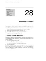
The information in Chapter 6 should be enough to get X up and running. There’salot
more to X than that, however, enough to fill manybooks. In this chapter we’ll look at
some of the more interesting topics:
• The next section describes the technical background of running X displays.
• On page 513 we’ll look at setting up the XF86Config file.
• On page 520 we’ll look at using more than one monitor with X.
• On page 521 we’ll look at using X in a network.
Xconfiguration: the theory
Setting up your XF86Config file normally takes a fewminutes, but sometimes you can
run into problems that makegrown men cry.Inthe rest of this chapter,we’ll look at the
technical background:
• Howdisplay boards and monitors work.
• Howtoset up XFree86 to work with your hardware.
• Howtotune your hardware for maximum display performance.
• Howtofry your monitor.
Imean the last point seriously: conventional wisdom says that you can’tdamage
hardware with a programming mistake, but in this case, you can, and people do it from
time to time. When you’ve read the section on howmonitors work, you’ll understand,
xtheory.mm,v v4.11 (2003/04/02 04:22:45) 505
Xconfiguration: the theory506
2April 2003, 17:00:47 The Complete FreeBSD (xtheory.mm), page 506
but please don’tstart tuning until you understand the dangers involved.
HowTVs and monitorswork
Youdon’thav e to be a computer expert to see the similarity between monitors and TVs:
current monitor technology is derivedfrom TV technology,and manyolder display
boards have modes that can use TVs instead of monitors. Those of us who were on the
microcomputer scene 20 to 25 years ago will remember the joyofgetting a computer
display on a portable TV,a‘‘glass tty’’connected by a serial line running at 300 or 1200
bps.
There are at least twoways to create pictures on a cathode ray tube: one is derivedfrom
oscilloscopes, where each individual character is scanned by the electron beam, rather
likewriting in the sand with your finger.Some early terminals used this technology,but
it has been obsolete for several decades.
TVs and monitors display the picture by scanning equally spaced lines across the entire
screen. Likeinabook, the first line starts at the top left of the screen and goes to the top
right. Each successive line starts slightly belowthe previous line. This continues until
the screen is full. The picture is formed by altering the intensity of the electron beam as
it scans the lines.
To perform this scan, the TV has two deflection units:one scans from left to right, and the
other scans, much more slowly,from top to bottom. Not surprisingly,these units are
called the horizontal and vertical deflection units. Youmay also encounter the terms line
and frame deflection.
Figure 28-1 shows the resultant pattern.
etc
First scan line
Second scan line
Flyback
Figure28-1: Scanning patternonthe monitor
xtheory.mm,v v4.11 (2003/04/02 04:22:45)
507 Chapter 28: XFree86 in depth
2April 2003, 17:00:47 The Complete FreeBSD (xtheory.mm), page 507
The tube can only move the electron beam at a finite speed. When the electron beam
reaches the right hand side of the screen, it needs to be deflected back again. This part of
the scan is called the horizontal flyback,and it is not used for displaying picture data.
The actual time that the hardware requires for the flyback depends on the monitor,but it
is in the order of 5% to 10% of the total line scan time. Similarly,when the vertical
deflection reaches the bottom of the screen, it performs a vertical flyback,which is also
not used for display purposes.
It’snot enough to just deflect, of course: somehowyou need to ensure that the scanning is
synchronized with the incoming signal, so that the scan is at the top of the screen when
the picture information for the top of the screen arrives. You’ve seen what happens when
synchronization doesn’twork: the picture runs up and down the screen (incorrect vertical
synchronization) or tears awayfrom the left of the screen (incorrect horizontal
synchronization). Synchronization is achievedbyincluding synchronization pulses in the
horizontal and vertical flyback periods. Theyhav e avoltage leveloutside the normal
picture data range to ensure that theyare recognized as synchronization pulses.
As if that wasn’tenough, the video amplifier,the part of the TV that alters the intensity of
the spot as it travels across the screen, needs time to ensure that the flyback is invisible,
so there are brief pauses between the end of the line and the start of the sync pulse, and
again between the end of the sync pulse and the beginning of the data. This process is
called blanking,and the delays are called the front porch (before the sync pulse) and the
backporch (after the sync pulse). Figure 28-2 depicts a complete scan line.
Sync pulse
Back porch Front porch
Sync pulse
Picture data
(Reference point) HDE SHR EHR HTRegisters:
Figure28-2: Scan line and register values
The register information at the bottom of the picture refers to the video controller
registers. We’ll look at howtointerpret them on page 509.
That, in a nutshell, is howhorizontal deflection works. Vertical deflection works in
almost the same way,just slower,with one minor exception. This basic display
mechanism was developed for TVs in the 1930s, at a time when terms likehigh-tech (or
xtheory.mm,v v4.11 (2003/04/02 04:22:45)
Xconfiguration: the theory508
2April 2003, 17:00:47 The Complete FreeBSD (xtheory.mm), page 508
ev enelectronics) hadn’tevenbeen invented, and eventoday we’re stuck with the lowdata
rates that theydecided upon in those days. Depending on the country,conventional TVs
display only 25 or 30 frames (pages of display) per second. This would cause an
unpleasant flicker in the display.This flicker is minimized with a trick called interlacing:
instead of displaying the frame in one vertical scan, the odd and evenlines are displayed
in twoalternating half frames, which doubles the apparent vertical frequency.
Howmonitorsdiffer from TVs
So howdoweapply this to computer displays? Let’slook at the US standard NTSC
system—the international PAL and SECAM systems are almost identical except for the
number of lines and a minor difference in the frequencies. NTSC specifies 525 lines, but
that includes the vertical flyback time, and in fact only about 480 lines are visible. The
aspect ratio of a normal TV is 4:3, in other words the screen is one-third wider than it is
high, so if we want square pixels,
1
we need to have one-third more pixels per line. This
means that we can display 640 pixels per line on 480 lines.
2
This resolution is normally
abbreviated to ‘‘640x480.’’ PAL and SECAM have lower vertical frequencies, which
allows a nominal 625 lines, of which about 600 are displayed. Either way,these values
have two huge disadvantages: first, the resolution is barely acceptable for modern
graphics displays, and secondly theyare interlaced displays. Older PC display hardware,
such as the CGA and some EGA modes, was capable of generating these signal
frequencies, but normal graphic cards can no longer do it. Instead, dedicated TV output
cards are available if that’swhat you want to do.
The first problem is interlace: it works reasonably for TVs, but it’sapain for computer
displays—there’sstill more flicker than a real 50 Hz or 60 Hz display.Modern display
boards can still run in interlace mode, but don’teventhink about doing so unless you’re
forced to—the resultant picture looks out of focus and is very tiring to read.
The second problem is the resolution: nowadays, 1024x768 is a minimum resolution, and
some monitors display up to 2048x1536 pixels. On the other hand, even60Hzrefresh
rate is barely adequate: read anymarketing literature and you’ll discoverthat 72 Hz is the
point at which flicker suddenly disappears. To get high-resolution, high refresh rate
displays, you need some very high internal frequencies—we’ll look at that further down.
Howtofry your monitor
Remember that a monitor is just a glorified TV? Well, one of the design constraints of
real TVs is that theyhav e only a single horizontal frequencyand only a single vertical
frequency. This simplifies the hardware design considerably: the horizontal deflection
uses a tuned circuit to create both the deflection frequencyand the high voltage required
to run the tube. This circuit is comprised of a transformer (the line transformer)and a
condenser.Run a line transformer evenfractionally offits intended frequencyand it runs
much less efficiently and use more current, which gets converted to heat. If you run a
conventional monitor offspec for anylength of time, it will burn out the line transformer.
1. Asquare pixel is one with the same height and width. Theydon’thav e to be that way,but it makes graphics
software much simpler.
2. Does this look familiar?
xtheory.mm,v v4.11 (2003/04/02 04:22:45)
509 Chapter 28: XFree86 in depth
2April 2003, 17:00:47 The Complete FreeBSD (xtheory.mm), page 509
Youdon’thav e to roll your own X configuration to burn out the monitor: 20 years ago,
the standard display boards were CGAs and HDAs,
1
and theyhad different horizontal
frequencies and thus required different monitors. Unfortunately,theyboth used the same
data connector.Ifyou connected an HDA(18.43 kHz horizontal frequency) to a CGA
monitor (15.75 kHz, the NTSC line frequency), you would soon see smokesignals.
All modern PC monitors handle at least a range of horizontal frequencies. This doesn’t
mean that an out of spec signal can’tdamage them—you might just burn out something
else, frequently the power supply.Most better monitors recognize out-of-spec signals
and refuse to try to display them; instead, you get an error display.Unfortunately,there
are plenty of other monitors, especially older or cheaper models, which don’tprotect
themselves against out of spec signals. In addition, just because the monitor displays
correctly doesn’tmean that it is running in spec. The moral of the story:
Never run your monitor out of spec. If your display is messed
up, there’sagood chance that the frequencies are out, so turn
offthe monitor.
Monitors aren’tthe only thing that you can burn out, of course. If you try hard, you can
also burn out chips on some display boards by running them at frequencies that are out of
spec. In practice, though, this doesn’thappen nearly as often.
Another difference between TVs and monitors is the kind of signal theytake. A real TV
includes a receiver, ofcourse, so you have anantenna connection, but modern TVs also
have connections for inputs from VCRs, which are usually twoaudio signals and a video
signal. The video signal contains fiveimportant components: the red, green and blue
signals, and the horizontal and vertical sync pulses. This kind of signal is called
composite video.Bycontrast, most modern monitors separate these signals onto separate
signal lines, and older boards, such as the EGA, evenused several lines per colour.
Unfortunately,there is no complete agreement about howthese signals should work: the
polarity of the sync pulses can vary,and some boards cheat and supply the sync pulses on
the green signal line. This is mainly of historical interest, but occasionally you’ll come
across a real bargain 20" monitor that only has three signal connections, and you may not
be able to get it to work—this could be one of the reasons.
The CRTcontroller
The display controller,usually called a CRT(Cathode Ray Tube) controller,isthe part of
the display board that creates the signals we’ve just been talking about. Early display
controllers were designed to produce signals that were compatible with TVs: theyhad to
produce a signal with sync pulses, front and back porches, and picture data in between.
Modern display controllers can do a lot more, but the principles remain the same.
The first part of the display controller creates the framework we’re looking for: the
horizontal and vertical sync pulses, blanking and picture information, which is
represented as a series of points or dots.Tocount, we need a pulse source, which also
1. Color Graphics Adapter and Hercules Display Adapter.
xtheory.mm,v v4.11 (2003/04/02 04:22:45)
Xconfiguration: the theory510
2April 2003, 17:00:47 The Complete FreeBSD (xtheory.mm), page 510
determines the duration of individual dots, so it is normally called a dot clock.For
reasons lost in history,CRT controllers start counting at the top left of the display,and not
at the vertical sync pulse, which is the real beginning of the display.Todefine a line to
the horizontal deflection, we need to set four CRTC registers to tell it—see the diagram
on page 507:
• The Horizontal Display End register (HDE) specifies howmanydots we want on
each line. After the CRTC has counted this manypixels, it stops outputting picture
data to the display.
• The Start Horizontal Retrace register (SHR) specifies howmanydot clock pulses
occur before the sync pulse starts. The difference between the contents of this
register and the contents of the HDE register defines the length of the front porch.
• The End Horizontal Retrace register (EHR) defines the end of the sync pulse. The
width of the sync pulse is the difference between the contents of this register and the
SHR register.
• The Horizontal Total register (HT) defines the total number of dot clocks per line.
The width of the back porch is the difference between the contents of this register and
the EHR register.
In addition, the Start Horizontal Blanking and End Horizontal Blanking registers (SHB
and EHB) define when the video signals are turned offand on. The server sets these
registers automatically,sowedon’tneed to look at them in more detail.
The control of the vertical deflection is similar.Inthis case, the registers are Vertical
Display End (VDE), Start Vertical Retrace (SVR), End Vertical Retrace (EVR), Vertical
Total (VT), Start Vertical Blanking (SVB), and End Vertical Blanking (EVB). The values
in these registers are counted in lines.
VGAhardware evolved out of older 8 bit character-based display hardware, which
counted lines in characters, not dot clocks. As a result, all of these registers are 8 bits
wide. This is adequate for character displays, but it’saproblem when counting dots: the
maximum value you can set in anyofthese registers is 255. The designers of the VGA
resorted to a number of nasty kludges to get around this problem: the horizontal registers
count in groups of 8 dot clocks, so theycan represent up to 2048 dot clocks. The vertical
registers overflowinto an overflowregister.Evenso, the standard VGA can’tcount
beyond 1024 lines. Super VGAs vary in howtheyhandle this problem, but typically they
add additional overflowbits. Togiv e you an idea of howclean the VGA design is,
consider the way the real Vertical Total (total number of lines on the display) is defined
on a standard VGA. It’sa10bit quantity,but the first 8 bits are in the VT register,the 9th
bit is in bit 0 of the overflowregister,and the 10th bit is in bit 5 of the overflowregister.
xtheory.mm,v v4.11 (2003/04/02 04:22:45)
511 Chapter 28: XFree86 in depth
2April 2003, 17:00:47 The Complete FreeBSD (xtheory.mm), page 511
The XF86Config mode line
One of the steps in setting up XFree86 is to define these register values. Fortunately,you
don’thav e to worry about which bits to set in the overflowregister: the mode lines count
in dots, and it’suptothe server to convert the dot count into something that the display
board can understand. Atypical Mode line looks like:
Modeline "640x480a" 28 640 680 728 776 480 480 482 494
These ten values are required. In addition, you may specify modifiers at the end of the
line. The values are:
• Alabel for the resolution line. This must be enclosed in quotation marks, and is used
to refer to the line from other parts of the XF86Config file. Traditionally,the label
represents the resolution of the display mode, but it doesn’thav e to. In this example,
the resolution really is 640x480, but the a at the end of the label is a clue that it’san
alternative value.
• The clock frequency, 28MHz in this example.
• The Horizontal Display End, which goes into the HDE register.This value and all
that followare specified in dots. The server mangles them as the display board
requires and puts them in the corresponding CRTC register.
• The Start Horizontal Retrace (SHR) value.
• The End Horizontal Retrace (EHR) value.
• The Horizontal Total (HT) value.
• The Vertical Display End (VDE) value. This value and the three following are
specified in lines.
• The Start Vertical Retrace (SVR) value.
• The End Vertical Retrace (EVR) value.
• The Vertical Total (VT) value.
This is pretty dry stuff. Tomakeiteasier to understand, let’slook at howwewould set a
typical VGA display with 640x480 pixels. Sure, you can find values for this setup in any
release of XFree86, but that doesn’tmean that they’re the optimum for your system.We
want a non-flicker display,which we’ll taketomean a vertical frequencyofatleast 72
Hz, and of course we don’twant interlace. Our monitor can handle anyhorizontal
frequencybetween 15 and 40 kHz: we want the least flicker,sowe’ll aim for 40 kHz.
First, we need to create our lines. Theycontain 640 pixels, twoporches and a sync pulse.
The only value we really knowfor sure is the number of pixels. Howlong should the
porches and the sync pulses be? If you have a good monitor with good documentation, it
should tell you, but most monitor manufacturers don’tseem to believe ingood
documentation. When theydodocument the values, theyvary significantly from monitor
to monitor,and evenfrom mode to mode: they’re not as critical as theylook. For
example, here are some typical values from my NEC 5D handbook:
xtheory.mm,v v4.11 (2003/04/02 04:22:45)