Chapter 13: Systems Engineering pdf
Bạn đang xem bản rút gọn của tài liệu. Xem và tải ngay bản đầy đủ của tài liệu tại đây (146.75 KB, 10 trang )
February 2003 13-1
Chapter 13
Systems Engineering
CONTENTS
13.1 INTRODUCTION 3
13.2 PROCESS DESCRIPTION 4
13.2.1 D
EVELOPMENT
P
HASING
4
13.2.2 S
YSTEMS
E
NGINEERING
P
ROCESS
4
13.2.2.1 Process Inputs 5
13.2.2.2 Requirements Analysis 5
13.2.2.3 Functional Analysis And Allocation 5
13.2.2.4 Design Synthesis 5
13.2.2.5 Process Outputs 5
13.2.2.6 System Analysis and Control 6
13.2.2.7 Other Activities 7
13.2.3 L
IFE
C
YCLE
I
NTEGRATION
7
13.2.4 C
OMMERCIAL
O
FF
-T
HE
-S
HELF
(COTS) 7
13.3 SYSTEMS ENGINEERING CHECKLIST 8
13.3.1 S
YSTEMS
E
NGINEERING
8
13.3.2 COTS [3] 9
13.4 REFERENCES 9
13.5 RESOURCES 9
Chapter 13: Systems Engineering Condensed GSAM Handbook
13-2 February 2003
This page intentionally left blank.
February 2003 13-3
Chapter 13
Systems Engineering
“That central life is somewhat superior to creation, superior to knowledge and thought, and contains all its cir-
cles.” – Ralph Waldo Emerson
13.1 Introduction
An arrow may seem like a simple object with a single, one-dimensional function – to kill or wound something. Nev-
ertheless, if one were asked to make an arrow, many questions would suddenly become critical. How big should the
feathers on the back end be? Are three feathers sufficient, or would four be better? Is there a better material than
feathers? What should the length, diameter, strength, and weight of the shaft be? What kind of point should the ar-
row have? What is it to be used against? How should it interface with the target? (i.e. How far must it penetrate?
How sharp should it be? Should it be bladed or round? Should it be made so that it cannot be withdrawn without
tearing up the target?) What materials have worked best in the past? Now that the arrow is seen as a collection of
components, how do the feathers and point connect to, or interface with, the shaft to form the arrow system? And
finally, how does the arrow interface with the bow to form the larger system of “bow and arrow?”
Today’s weapon systems are far more complex than the bow and arrow. But in like manner they are composed of
systems of subsystems and components. In some cases, systems are even composed of other systems. Also in like
manner, each subsystem must be analyzed to correctly specify its requirements, and then be designed so that it will
meet the subsystem requirements, interface correctly with the other subsystems to form the system, and meet the
system requirements. These are many aspects of systems engineering. But they are not all of systems engineering.
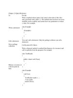
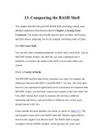
Figure 13-1 shows a summary of the overall scope of this discipline that spans the product life cycle.
Product Delivered
Exploration
Customer Needs
Technology
Availability
Product Line
Availability
Proposal or R&D
Management
Concept Synthesis
Specific Analyses
Development
Technical
Management
Technical Generalist
Technical Specialist
Operations
Major and Minor
Upgrades
Anomaly Investigation
Anomaly Resolution
Organizational Liaison
Go-Ahead to Develop or Purchase
Product Retired
Time
Figure 13-1 Scope of Systems Engineering [1]
Many of the other chapters in this book deal with project management principles and issues. By contrast, systems
engineering consists more of technical principles and issues. While the overall project is directed by a Project Man-
ager (PM), who directs the project toward project success, systems engineering is a technical discipline and should
be led by a skilled and experienced Systems Engineer (SE), whose primary goal is product success. Systems engi-
neering transforms an operational need into a set of system performance parameters and a preferred system configu-
ration. [2]
When projects with technical problems are analyzed to determine the root of their trouble, the majority can trace the
cause back to insufficient or improper systems engineering. The complexity of modern systems makes it an absolute
necessity to divide the product into various segments and subsystems, employing many disciplines to design and
Chapter 13: Systems Engineering Condensed GSAM Handbook
13-4 February 2003
build these parts of the whole. However, the parts will not work together unless there is an effective system-level
designer and builder ensuring all the parts interface, work together, and meet the requirements. Systems engineering
defines the system requirements and specifications, designs the system, including allocating functionality to subsys-
tems, and continues to monitor and assist product development until integration and testing are complete to make
sure the system is built according to specifications.
13.2 Process Description
Systems engineering can be divided into two ma-
jor sub-disciplines. The first is the actual technical
knowledge domain, usually referred to systems
engineering. The second is systems engineering
management. Often, one or the other of these two
is mistaken as the whole discipline. Systems en-
gineering management consists of three primary
activities, development phasing, life cycle inte-
gration, and the systems engineering process.
These activities are shown, along with their prod-
ucts or sub-activities in Figure 13-2.
13.2.1 Development Phasing
The design process is a series of development
stages where progressively more detailed sys-
tems descriptions or designs are produced. To
begin, studies of what the system should do and how it would operate are performed and documented in the system
concept. This is the first look at whether there is a feasible solution to the operational need. Assuming the conceptual
system is technically, operationally, and economically feasible, development proceeds through system development
to produce a functional baseline, where all the functions the system are identified and specified. The next step is the
preliminary design, during which subsystems are defined and the functions are allocated to the various subsystems
to create the allocated baseline. The final step in this process is the detailed design. During this phase actual prod-
ucts to perform the functions are identified for acquisition or development, producing the product baseline. This
stepped process is shown in Figure 13-3. [2]
Concept Studies
System Definition
System Concept
Description
Preliminary Design
Functional
Baseline
Allocated
Baseline
Detailed Design
Product
Baseline
Figure 13-3 Steps and Products of Development Phasing
13.2.2 Systems Engineering Process
While development phasing determines what major design activities are performed, the actual process performed is
known as the systems engineering process, shown in Figure 13-4.
Life Cycle
Integration
Development
Phasing
Systems
Engineering
Process
Systems
Engineering
Management
Life Cycle
Planning
Baselines
Integrated
Teaming
Figure 13-2 Systems Engineering Management Activities [2]
Condensed GSAM Handbook Chapter 13: Systems Engineering
February 2003 13-5
Requirements
Analysis
Functional
Analysis and
Allocation
Design
Synthesis
Requirements
Loop
Design Loop
System Analysis
and Control
Input
Output
Verification
Figure 13-4 Systems Engineering Process [2]
13.2.2.1 Process Inputs
The inputs to this process consist of customer requirements in the form of needs, objectives, missions, environments,
constraints, and measures of effectiveness. Other inputs include the available technology base, previous program
requirements, program decision requirements, and standards and specifications requirements. [2]
13.2.2.2 Requirements Analysis
The systems engineering process begins with requirements analysis. During this activity missions and environments
are analyzed and functional requirements are identified. Additionally, performance and design constraint require-
ments are defined and refined. [2]
13.2.2.3 Functional Analysis And Allocation
During the next step, functional analysis and allocation, the requirements are decomposed into lower level functions
and all performance and constraint requirements are allocated to functional levels. Internal and external functional
interfaces are defined and a functional architecture is produced.[2]
13.2.2.4 Design Synthesis
The third activity, design synthesis, transforms a functional architecture to a physical architecture. Alternative sys-
tem elements, concepts, and configuration items are defined and preferred product sets and processes are identified.
The internal and external physical interfaces are also defined and refined. This activity is iterated until a system ar-
chitecture is developed. [2]
13.2.2.5 Process Outputs
The outputs of the systems engineering process include documentation of the alternatives and all decisions. They
also include the specifications and baselines and architectures. The architecture development is shown in Figure 13-
5.
Chapter 13: Systems Engineering Condensed GSAM Handbook
13-6 February 2003
Functional Architecture
Requirements
Functional &
Performance
Requirements
& Interfaces
Physical Architecture
Sub-Systems,
Components, &
Interfaces
I/F
I/F
I/F
I/F
System Architecture
Products &
Interfaces
I/F
I/F
I/F
I/F
Design Synthesis
Functional Analysis & Allocation
Design Synthesis
I/F I/F I/F
I/F
Figure 13-5 Systems Engineering Architecture Development
13.2.2.6 System Analysis and Control
The systems engineering process activities are augmented and controlled by auxiliary system analysis and control
functions. These functions include activities to measure progress, evaluate and select alternatives, and document all
activity and decisions. The following list contains examples of system analysis and control activities.
• Determine and track requirements • Maintain liaison with the customer/user.
• Track decisions and decision rationale. • Track cost and schedule.
• Maintain technical baselines. • Track technical performance.
• Manage and maintain interface definitions. • Verify requirements are met.
• Identify and manage risks. • Review and monitor progress.
• Control the Configuration. • Document the Configuration.
Condensed GSAM Handbook Chapter 13: Systems Engineering
February 2003 13-7
13.2.2.7 Other Activities
The requirements and design loops are used to reevaluate the previous work in light of current activities. It is often
found that further refinement of requirements, allocations, and designs are necessary and desirable after discovering
additional data at the next level of development. The final activity is verification. When baselines and architectures
are completed, they are compared to the requirements to ensure the solutions fulfill the requirements. All require-
ments should be verifiable and systems engineering documentation should define the method used for verification of
each requirement. [2]
13.2.3 Life Cycle Integration
Life cycle integration is the concurrent consideration of all life cycle needs during the development process. For
example, wouldn’t it be nice if the manufacturer of your car had given more thought to the location of the oil filter,
spark plugs, and other user serviceable components when designing your car’s engine? In other words, rather than
just producing a system that meets the initial requirements, life cycle integration designs a system or product that
considers, as a minimum, the product life cycle functions in the following list. [2]
• Manufacturing/Production • Verification • Development
• Deployment • Operation • Support
• Disposal • Training
DoD policy requires integrated product development to be implemented at all levels of acquisition. This is usually
accomplished through the use of Integrated Product Teams (IPTs). IPTs are comprised of members from multiple
disciplines to ensure considerations from all life cycle phases and functions are considered when developing a prod-
uct. [2]
13.2.4 Commercial Off-The-Shelf (COTS)
A significant change to military acquisition that has been implemented during the last decade is the use of commer-
cial components and assemblies that are already developed and available for sale in the public marketplace. The idea
behind this change is, “If there is a commercial product already built that will satisfy our requirements, let’s buy it
instead of developing our own.” This may require the lowering of standards so that the commercial product will
meet the requirements. However, if a realistic appraisal determines that military specifications are not needed in a
particular acquisition, there are several potential benefits that may be realized. They include: [3]
• Reduced or eliminated development costs. • Product Improvements paid for by vendor.
• Reduced or eliminated development schedule. • Wide user base to prove the product.
• Available skill base. • Industry investment in technology base.
• Lower acquisition costs. • More component or vendor alternatives.
So what was the reason to buy military components in the first place? First, the military often needs to be able to
operate under more severe environmental conditions than the average buyer. Because of the critical nature of the
military’s mission, drawings, specifications, and source code are often needed to be able to maintain systems as long
as the military needs them, not just until the industry decides to move on to something else. There are other factors
to consider, including security issues, product changes, safety issues, and compatibility with existing systems.
While it may appear to be a case of “faster and cheaper” COTS components vs. “better” mil spec components, there
are a number of risks that must be considered before deciding to acquire COTS instead of developing an item. These
are some of the major concerns: [3]
1. Support (maintenance and logistics) may not be responsive enough to meet your requirements.
2. Unforeseen environmental conditions may fall outside the COTS product specifications.
3. There may be incompatibilities with hardware, software, processes, or the operational environment.
Chapter 13: Systems Engineering Condensed GSAM Handbook
13-8 February 2003
4. Verification and validation effort and costs may be higher than anticipated.
5. Integration may be more difficult than estimated.
6. Training costs may be higher than for government-developed systems.
7. Operation and maintenance costs may be higher than for equivalent government components.
8. Vendor viability (technical proficiency, stability, dependency on other sources).
9. Security questions may be unresolved. Is there hidden, malicious code, a “back door,” or easily bypassed
security checks?
10. Product volatility. Product changes are subject to the vendor’s choices and timing.
11. Product quality may be lower than required, impacting reliability, safety, maintainability, and other consid-
erations.
In order to reduce the effects of risks involved with COTS products in an acquisition or development project, the
following mitigation techniques should be employed. [3]
1. Thoroughly understand the requirements of the system to be built.
2. Use good systems engineering practices, i.e., understand the functions the COTS software is to perform and
the necessary interfaces with the remainder of the system.
3. Gain knowledge about the marketplace and vendors. Know which are viable.
4. Learn about the products, i.e., the functions performed and the required interfaces, to be able to make in-
formed judgments.
5. Understand which things must change the least and which things are likely to change the most.
6. Know all the options.
7. Conduct a make vs. buy vs. rent trade study.
8. Reduce integration and other issues by designing around a major COTS product.
9. Employ industry standards wherever feasible.
10. Establish a robust verification plan and environment.
11. Involve the vendor throughout the life cycle.
12. Get product or vendor certification if possible.
13. Have vendor put source code into “escrow” for future needs.
14. Consider a product line approach.
13.3 Systems Engineering Checklist
This checklist is provided to assist you in understanding the systems engineering issues of your project. If you can-
not answer a question affirmatively, you should carefully examine the situation and take appropriate action.
13.3.1 Systems Engineering
! 1. Do you understand the systems engineering process?
! 2. Are you implementing an optimal systems engineering process?
! 3. Have you implemented proper and sufficient systems engineering controls and techniques?
! 4. Are you implementing systems engineering across the whole development life cycle?
! 5. Is there an experienced and skilled systems engineer directing the systems engineering effort?
Condensed GSAM Handbook Chapter 13: Systems Engineering
February 2003 13-9
! 6. Is a systems engineering representative providing input to or comments on all product change proposals?
! 7. Is the systems engineer seeing that all the various development efforts are coordinated and integrated?
! 8. Do you know what software development life cycle your project will be employing and how it coordinates
with the software and project life cycles?
! 9. Are you considering all phases of the entire life cycle in your requirements, architectures, and designs?
! 10. Are you implementing an integrated product environment?
! 11. Have you established integrated (interdisciplinary) product teams?
! 12. Have you included all the necessary disciplines on the integrated product teams?
! 13. Are you documenting all studies, decisions, and configurations?
! 14. Have all internal and external interfaces been defined?
! 15. Are all your requirements verifiable?
! 16. Do all your requirements trace to products and vice versa?
13.3.2 COTS [3]
! 17. Do you conduct make vs. buy vs. rent trade studies instead of just assuming that buy is the right choice?
! 18. Do you use your requirements as the criteria for your trade studies?
! 19. Do you consider the full life cycle when deciding whether to make, buy, or rent?
! 20. Do you know all your options?
! 21. Are you knowledgeable of the marketplace and the vendors?
! 22. Does the vendor understand your needs?
! 23. Are you not lowering your requirements indiscriminately to use COTS?
! 24. Do you understand the total life cycle costs?
! 25. Are the product and vendor likely to be around for the lifetime of the system?
! 26. Have you satisfactorily resolved all security issues?
! 27. Have you reduced all known risks to an acceptable level?
13.4 References
[1] Sarah A. Sheard, et al, “Systems Engineering Beyond Capability Models,” Proceedings of INCOSE, Aug. 2002.
[2] System Engineering Fundamentals, 2001, Defense Acquisition University:
www.dau.mil/pubs/gdbks/sys_eng_fund.asp
[3] Kohl, Ronald J., “COTS Based Systems: Benefits, Potential Risks and Mitigation Techniques”:
www.geia.org/etmconf/Workshop/sed/COTS_Issues.pdf
13.5 Resources
Commercial Item Acquisition Report, OSD. Download PDF: www.acq.osd.mil/ar/doc/cotsreport.PDF
Commercial Item Handbook, OSD. Download PDF: www.acq.osd.mil/ar/doc/cihandbook.pdf
CPATS – Systems Engineering, Defense Acquisition Deskbook:
/>=L2-1&Exp=N&Doc=/reflib/daf/019gz/001/019gz001doc.htm&BMK=C1021
Crosstalk Magazine: www.stsc.hill.af.mil/crosstalk/
Chapter 13: Systems Engineering Condensed GSAM Handbook
13-10 February 2003
− “Opportunities and Complexities of Applying Commercial-Off-the-Shelf Components”:
www.stsc.hill.af.mil/crosstalk/1998/04/applying.asp
− “An Activity Framework for COTS-Based Systems”:
www.stsc.hill.af.mil/crosstalk/2000/09/brownsword.html
− “The Double-Edged COTS IT Sword”: www.stsc.hill.af.mil/crosstalk/1998/04/publisher.asp
− “Evaluating COTS Using Function Fit Analysis”: www.stsc.hill.af.mil/crosstalk/2000/02/holmes.html
− “A Web Repository of Lessons Learned from COTS-Based Software Development1”:
www.stsc.hill.af.mil/crosstalk/2002/09/rus.html
− “A COTS-Based Replacement Strategy for Aging Avionics Computers”:
www.stsc.hill.af.mil/crosstalk/2001/12/haldeman.html
− “The Commandments of COTS: Still in Search of the Promised Land”:
www.stsc.hill.af.mil/crosstalk/1997/05/commandments.asp
− “Lessons Learned From Using COTS Software on Space Systems”:
www.stsc.hill.af.mil/crosstalk/2001/06/adams.html
DERA Systems Engineering Practices Reference Model: www.incose.org/stc/SEGD12_2.htm
Hitchens, Derek, Systems Thinking, Engineering, & Management site: www.hitchins.co.uk/STEM.html
International Council on Systems Engineering: www.incose.org/
NASA Systems Engineering Handbook:
ldcm.gsfc.nasa.gov/library/ NASA%20Syst%20Eng%20Handbook.pdf
Program Manager’s Guide for Managing Software, 0.6, 29 June 2001, Chapter 7:
www.geia.org/sstc/G47/SWMgmtGuide%20Rev%200.4.doc
SEI 1998 Software Symposium on COTS. Download slides: www.sei.cmu.edu/cbs/cbs_slides/98symposium/
Sheard, Sara A., et al, “Systems Engineering Standards and Models Compared”:
www.software.org/pub/ExternalPapers/9804-2.html
Sheard, Sara A., et al, “Systems Engineering Beyond Capability Models”:
www.software.org/pub/ExternalPapers/SEBeyondCM.doc
System Engineering Fundamentals, 2001, Defense Acquisition University, download at:
www.dau.mil/pubs/gdbks/sys_eng_fund.asp
Systems Engineering Guide, Version 1.1, 5 April 1996, ASC/EN SMC/SD:
/>University of Maryland, COTS Lessons Learned database: />