Part 7: Specification for materials and workmanship: cold formed sections potx
Bạn đang xem bản rút gọn của tài liệu. Xem và tải ngay bản đầy đủ của tài liệu tại đây (491.25 KB, 20 trang )
BRITISH STANDARD
BS 5950-7:
1992
Structural use of
steelwork in building —
Part 7: Specification for materials and
workmanship: cold formed sections
BS5950-7:1992
This British Standard, having
been prepared under the
direction of the Civil
Engineering and Building
Structures Standards Policy
Committee, was published
under the authority of the
Standards Board and comes
intoeffecton
28February1992
© BSI 12-1998
The following BSI references
relate to the work on this
standard:
Committee reference CSB/27
Draft for comment88/10164 DC
ISBN 0 580 20313 1
Committees responsible for this
British Standard
The preparation of this British Standard was entrusted by the Civil
Engineering and Building Structures Standards Policy Committee (CSB/-) to
Technical Committee CSB/27, upon which the following bodies were
represented:
British Constructional Steelwork Association Ltd.
British Industrial Fasteners Federation
British Railways Board
British Steel Industry
Department of the Environment (Building Research Establishement)
Department of the Environment (Construction Directorate)
Department of the Environment (Property Services Agency)
Health and Safety Executive
Institution of Civil Engineers
Institution of Structural Engineers
Royal Institute of British Architects
Steel Construction Institute
Welding Institute
The following bodies were also represented in the drafting of the standard,
through subcommittees and panels:
Cold Rolled Sections Association
Construction Industry Research and Information Association
Flat Roofing Contractors’ Advisory Board
Metal Roof Deck Association
Storage Equipment Manufacturers Association
Amendments issued since publication
Amd. No. Date Comments
BS5950-7:1992
© BSI 12-1998
i
Contents
Page
Committees responsible Inside front cover
Foreword iii
Section 1. General
1.1 Scope 1
1.2 Definitions 1
1.3 Major symbols 1
Section 2. Materials
2.1 Structural steel 2
2.1.1 Steels for cold formed sections 2
2.1.2 Steels for profiled sheet 2
2.1.3 Other steels 2
2.1.4 Strength of steels 2
2.2 Fasteners 2
2.2.1 Ordinary bolts 2
2.2.2 Plain washers 2
2.2.3 High-strength friction grip fasteners 2
2.2.4 Screw fasteners 2
2.2.5 Rivets 2
2.2.6 Powder-actuated fasteners 2
2.3 Welding consumables 3
Section 3. Fabrication
3.1 Methods 4
3.2 Cutting 4
3.3 Holing 4
3.4 Identification 4
3.5 Handling and storage 4
3.6 Repair of protective coatings 4
Section 4. Assembly and erection of structures in cold formed sections
4.1 General 5
4.2 Bolting 5
4.3 Friction grip fasteners used in the pre-tensioned condition 5
4.4 Screw fixings 5
4.5 Rivets 5
4.6 Welding 5
4.6.1 Arc welding 5
4.6.2 Spot welding 5
4.7 Erection 5
4.7.1 General 5
4.7.2 Purlins and sheeting rails 6
4.7.3 Alignment 6
4.7.4 Accuracy of construction 6
4.7.5 Supports and foundations 6
4.8 Erection tolerances 6
4.8.1 General 6
4.8.2 Connection to concrete elements 6
4.8.3 Column bases 6
4.8.4 Plumbing and alignment of columns 7
4.8.5 Position in plan of members 7
BS5950-7:1992
ii
© BSI 12-1998
Page
4.8.6 Levels 7
4.9 Protective treatment 7
Section 5. Manufacturing and fabrication tolerances
5.1 General 8
5.2 Dimensional tolerances — cold formed open sections 8
5.2.1 Position of measurement 8
5.2.2 Thickness 8
5.2.3 External dimensions 8
5.2.4 Length 8
5.2.5 Angular tolerances 9
5.2.6 Straightness 9
5.2.7 Angle of twist 9
5.2.8 Compound members 9
5.3 Dimensional tolerances — profiled sheets 9
5.3.1 Thickness 9
5.3.2 Length 9
5.3.3 Out-of-squareness 9
5.3.4 Straightness 9
5.3.5 Bulging or contraction 9
5.3.6 Dimensions of profiled sheets 10
Appendix A General recommendations for steelwork tenders
and contracts 11
Figure 1 — Internal element of open section 8
Figure 2 — Outstand element 8
Figure 3 — Deviation from straightness for cold formed sections 9
Figure 4 — Deviation from squareness 9
Figure 5 — Deviation from straightness for profiled sheets 9
Figure 6 — Bulging and contraction of a profiled sheet 10
Figure 7 — Profiled sheet 10
Table 1 — Internal elements of open sections 8
Table 2 — Outstand elements 8
Table 3 — Profiled sheets 10
Publication(s) referred to 12
BS 5950-7:1992
© BSI 12-1998
iii
Foreword
This Part of BS5950 has been prepared under the direction of the Civil
Engineering and Building Structures Standards Policy Committee. BS5950 is a
document combining codes of practice to cover the design, construction and fire
resistance of steel structures and specifications for materials, workmanship and
erection.
It comprises the following Parts:
— Part1: Code of practice for design in simple and continuous construction: hot
rolled sections;
— Part2: Specification for materials, fabrication and erection: hot rolled
sections;
— Part3: Design in composite construction;
— Section3.1: Code of practice for design of simple and continuous composite
beams;
— Section3.2
1)
: Code of practice for design of composite columns and frames;
— Part4: Code of practice for design of floors with profiled steel sheeting;
— Part5: Code of practice for design of cold formed sections;
— Part6
1)
: Code of practice for design of light gauge profiled sheeting;
— Part7: Specification for materials and workmanship: cold formed sections
and profiled sheets;
— Part8: Code of practice for fire resistant design;
— Part9
1)
: Code of practice for stressed skin design.
It has been assumed in the drafting of this British Standard that the execution of
its provisions will be entrusted to appropriately qualified and experienced people.
A British Standard does not purport to include all the necessary provisions of a
contract. Users of British Standards are responsible for their correct application.
Compliance with a British Standard does not of itself confer immunity
from legal obligations.
Summary of pages
This document comprises a front cover, an inside front cover,pages i to iv,
pages1 to12, aninside back cover and a back cover.
This standard has been updated (see copyright date) and may have had
amendments incorporated. This will be indicated in the amendment table on
theinside front cover.
1)
In preparation.
iv
blank
BS 5950-7:1992
© BSI 12-1998
1
Section 1. General
1.1 Scope
This Part of BS5950 specifies requirements for the
materials, fabrication and erection, using cold
formed sections, of structural steelwork in building.
It also specifies requirements for profiled sheets for
cladding, roof decking and flooring in buildings up to
the time the product is delivered to the building site,
but not for their erection on site.
The special requirements pertaining to the
fabrication of curved profiled sheets are not
included.
NOTE1The installation of profiled steel sheet cladding is
covered in BS5427.
2)
The requirements given in this Part apply to the
materials and the assembly process, but the
designer needs to be aware of those items which
affect the design.
NOTE2The requirements specified herein, whilst suitable for
inclusion in contract documents, may need to be modified to align
with specific needs.
NOTE3The titles of the publications referred to in this
standard are listed on page12.
1.2 Definitions
For the purposes of this Part of BS5950, the
following definitions apply.
1.2.1
designer
appropriately qualified and experienced person
responsible for the structural design
1.2.2
fabricator
organization which produces finished steel
members ready for assembly on site
1.2.3
manufacturer
organization which produces a basic structural
component, such as a bolt, a steel section or a steel
sheet
1.3 Major symbols
2)
Some requirements for the erection, use and maintenance of profiled sheets in buildings are given in ECCS41 “European
Recommendations for Steel Construction: Good practice in steel cladding and roofing” published by the European Convention for
Constructional Steelwork, obtainable from the Steel Construction Institute, Silwood Park, Buckhurst Road, Ascot, Berkshire
SL57QN.
B flange width
C outstand
D profile depth
L length
W cover width
e deviation
t thickness
BS5950-7:1992
2
© BSI 12-1998
Section 2. Materials
2.1 Structural steel
2.1.1 Steels for cold formed sections
Steels used for the manufacture of cold formed
sections for use as structural members shall comply
with the requirements for the relevant strength
grade of one of the standards listed below, but
excluding grades with a minimum yield strength
greater than450N/mm
2
, as follows:
BS1449-1
BS2989
BS6830
BS EN10025
BS EN10130
BS EN10142
When an organic coating or metallic coating not
covered by BS2989 is applied before forming it shall
be as specified by the designer.
NOTEIt is expected that further European Standards in the
BSEN10xxx series will gradually supersede BS1449, BS2989
and BS6830.
2.1.2 Steels for profiled sheet
Steels used for the manufacture of profiled sheet for
use as roof or wall cladding, roof decking or flooring
shall comply with the requirements for the relevant
strength grade of one of the following:
BS1449-1
BS2989
BS6830
BS EN10130
BS EN10142
When an organic coating or metallic coating not
covered by BS2989 is applied before forming it shall
be as specified by the designer.
NOTE1The specific requirements for material in profiled steel
sheets are given in BS5950-4.
NOTE2See note to2.1.1.
2.1.3 Other steels
Where steels other than those specified in2.1.1
or2.1.2 are to be used, they shall meet the relevant
performance requirements of the appropriate
British Standards cited in2.1.1 and2.1.2.
2.1.4 Strength of steels
Where the material used to manufacture cold
formed sections or profiled steel sheets is supplied
as complying with the requirements of grades HR3
or HR4 of BS1449, or of grades Z1 or Z2 of
BS2989, the design strength shall be taken as the
relevant value given in BS5950-5 or BS5950-6 as
appropriate.
For further certificated steels, the minimum yield
strength given in the relevant specification shall be
used for the formed section or profiled sheet.
Alternatively, for any steel, the strength of the sheet
material shall be determined by testing in
accordance with BSEN10002-1. Every coil or
bundle of material used shall be tested and test
certificates shall be provided if required.
Where the steel section or sheet is to be hot dip
galvanized, or undergoes any other heating process
after fabrication, steps shall be taken to ensure that
the design strengths given in BS5950-4, BS5950-5
or BS5950-6, as appropriate, are achieved.
2.2 Fasteners
2.2.1 Ordinary bolts
Ordinary bolts and nuts shall comply with BS3692,
BS4190 or BS4933 as appropriate, or alternatively
with the strength grades of BS3692 but with the
dimensions, finish and tolerances of BS4190. In
either case, the nuts shall be of at least the strength
grade appropriate to the grade of bolt with which
they are used. As a third alternative, bolts and nuts
complying with BS4395 shall be used.
2.2.2 Plain washers
Plain washers for use with ordinary bolts and nuts
shall comply with BS4320.
2.2.3 High-strength friction grip fasteners
High-strength friction grip bolts, nuts and washers
shall comply with BS4395, except where other
proprietary types are specified or approved by the
designers. Where other proprietary types of
high-strength friction grip fasteners are used, they
shall have mechanical properties similar to bolts
complying with BS4395 and shall be capable of
being reliably tightened to at least the minimum
preloads specified in BS4604.
2.2.4 Screw fasteners
Self-tapping screws shall comply with BS4174.
All other proprietary screw fasteners shall be as
specified or approved by the designer.
2.2.5 Rivets
Rivets shall comply with BS641 or BS4620.
All other proprietary rivets shall be as specified or
approved by the designer.
2.2.6 Powder-actuated fasteners
Powder-actuated fasteners shall be as specified or
approved by the designer. The thickness of the base
material into which the fastener is fixed shall be not
less than6mm.
BS5950-7:1992
© BSI 12-1998
3
Section 2
2.3 Welding consumables
All welding consumables shall comply with BS639
or BS2901-1 as appropriate.
The welding consumables and procedures used shall
be such that the yield strength and the tensile
strength of deposited weld metal shall be not less
than the respective minimum values for the parent
metal being welded, except where the designer
specifies or approves the use of lower strength
welds.
BS5950-7:1992
4
© BSI 12-1998
Section 3. Fabrication
3.1 Methods
Fabrication methods shall be chosen so as to
minimize any damage to pre-applied protective
coatings. Where any damage does occur it shall be
made good as specified in3.6.
3.2 Cutting
Cutting shall be by shearing, cropping or sawing.
Burrs which can cause injury or prevent the proper
alignment or bedding of sections or sheeting shall be
removed. After cutting, all parts required to be in
surface-to-surface contact shall be free from
distortion.
3.3 Holing
Holes in cold formed sections shall be punched or
drilled. The holes shall be free from burrs which
would prevent solid seating of the parts after
tightening.
Slotted holes shall either be punched in one
operation or else formed by punching or drilling two
round holes and completed by high-quality flame
cutting and dressing to ensure that the bolt can
freely travel the full length of the slot.
3.4 Identification
Where required by the purchaser, each piece or
bundle shall be suitably identified or marked before
delivery in such a way that will facilitate the
erection sequence. The mark shall not damage the
material.
3.5 Handling and storage
Cold formed sections, profiled sheets and
accessories shall be suitably packed and stored to
provide protection against any damage. All material
shall be handled in such a way as to prevent any
damage. Any necessary repairs shall be carried out
in such a way as not to weaken the material or
damage the protective coating.
3.6 Repair of protective coatings
Where damage to protective coating has occurred,
repairs shall be carried out to restore the coating to
the specified quality of protection.
BS 5950-7:1992
© BSI 12-1998
5
Section 4. Assembly and erection of structures in
cold formed sections
4.1 General
All components shall be assembled and erected in
such a manner that they are not bent, twisted or
otherwise damaged.
Drifting to align holes shall not enlarge the holes or
distort the metal.
4.2 Bolting
It shall be assumed that washers are required
except where the drawings or design documents
state that washers are not required. Where washers
are required, they shall be used under both the bolt
head and the nut. In the case of countersunk bolts,
washers shall be used under the nut.
NOTE1Where it is proposed to specify or agree that washers
need not be used, reference should be made to 8.2.5 of
BS5950-5:1987.
The threaded portion of each bolt shall project
through the nut at least one thread.
The nuts on connections subject to vibration shall be
secured to prevent loosening. Self-locking nuts shall
be used or else the nuts shall be secured by the use
of locknuts or upsetting of the threads of the bolts
after assembly and tightening.
Where slotted holes are provided for movement
connections, the joint shall be free to move over the
full length of the slots. Slots in an outer ply shall be
covered by cover plates of appropriate dimensions
and thickness.
All bolts, nuts and washers shall be protected
against corrosion. Where the connected parts are
protected against corrosion, the protection system
used for the bolts shall be compatible (see4.9).
Bolts, nuts and washers used to connect
metal-sprayed or galvanized steelwork shall be
spun galvanized or sherardized or else electroplated
with zinc, cadmium or aluminium.
NOTE2Electroplated finishes may not provide the same
degree of protection as metal-sprayed or galvanized steelwork.
4.3 Friction grip fasteners used in the
pre-tensioned condition
The use of pre-tensioned high-strength friction grip
bolts complying with BS4395 shall be in accordance
with BS4604.
Where the use of other types of pre-tensioned
friction grip fasteners is permitted (see2.2.3), they
shall be installed in accordance with the
manufacturer’s recommendations and shall be
tightened to at least the minimum shank tensions
specified in BS4604.
4.4 Screw fixings
Screw fixings shall be installed in accordance with
the manufacturer’s recommendations.
4.5 Rivets
Rivets shall be installed in accordance with the
manufacturer’s recommendations.
4.6 Welding
4.6.1 Arc welding
Arc welding shall be in accordance with BS5135.
NOTE1For through-deck welding reference should be made to
appendix A of BS5950-3.1:1990.
Fusion faces and the surrounding surfaces shall be
free from heavy scale, moisture, oil, paint or any
other substance which might affect the quality of
the weld or impede the progress of welding.
NOTE2This is particularly important when a
hydrogen-controlled welding process is used. Certain proprietary
protective coatings are specially formulated with the intention
that they should not interfere with welding. The use of such
coatings is not excluded by the requirements of this clause but, if
so required, their acceptability should be demonstrated by means
of specimen welds (see BS6084).
4.6.2 Spot welding
Resistance spot welding of coated and uncoated
steel shall be in accordance with BS1140.
4.7 Erection
4.7.1 General
The erection of the steelwork for the structural
frame shall be planned and carried out so as to
ensure safe working conditions at all times.
NOTEFor guidance, reference may be made to BS5531 and
Health and Safety document GS28.
3)
Throughout the erection of the structure, the
steelwork shall be securely bolted or fastened in
order to ensure that it can adequately withstand all
loadings liable to be encountered during erection,
including, where necessary, those from erection
plant and its operation. Any temporary bracing or
temporary restraint shall be left in position until
such time as erection is sufficiently advanced so as
to allow its safe removal.
All connections to any temporary bracing or other
members provided for erection purposes shall be so
made that they do not weaken the permanent
structure or impair serviceability.
3)
Available from HMSO,49 High Holborn, London WC1V6HB (for personal callers) or by post from HMSO Publications Centre,
PO276, London SW185DT.
BS5950-7:1992
6
© BSI 12-1998
Section 4
4.7.2 Purlins and sheeting rails
Where anti-sag bars are used, they shall be installed
prior to the commencement of fixing the cladding.
4.7.3 Alignment
Each part of the structure shall be aligned as soon
as practicable after it has been erected. Permanent
connections shall not be made between members
until sufficient of the structure has been aligned,
levelled, plumbed and temporarily connected to
ensure that members will not be displaced during
subsequent erection or alignment of the remainder
of the structure.
4.7.4 Accuracy of construction
The accuracy with which the steelwork is erected
shall be as stated on the drawings or in the design
documents. Where values are not specified, those
given in4.8 shall be applied.
Due account shall be taken of the effects of
temperature on the structure and on the measuring
instruments whenever measurements are made for
setting-out and erection or for any subsequent
dimensional checks.
4.7.5 Supports and foundations
4.7.5.1 Positioning and setting-in of foundation
bolts
Foundation bolts shall be set out within the limits
for position and level specified in4.8
Foundation bolts shall be held firmly in position
during all setting-in operations, and care shall be
taken to ensure that the full movement tolerances
are achieved.
Bolts, threads and nuts shall be protected against
damage, cement grout, corrosion, etc. at all stages of
construction.
Where tubes are to be concreted into foundations to
be used at a later stage for grouting-up of bolt
pockets, they shall be securely fixed and effectively
sealed to prevent ingress of grout from the
surrounding concrete during placing operations.
Pockets formed around fabrication bolts shall be
kept clean and free from debris, water, etc.
Proprietary bolting systems shall be used in
accordance with the manufacturer’s
recommendations.
4.7.5.2 Packings
Packs, shims and other supporting devices shall be
flat, of adequate strength and rigidity, and not
larger than necessary. Where packings are to be left
in position and subsequently grouted, they shall be
placed such that they are totally enclosed by the
grout.
4.7.5.3 Bedding and grouting up of structures
No grouting shall be carried out until a sufficient
portion of the structure (for multistorey buildings, a
sufficient number of bottom lengths of stanchions)
has been aligned, levelled, plumbed and adequately
braced by other structural components which have
been levelled and are securely held by their
permanent connections.
Immediately before grouting, the space under the
steel shall be clear of all debris and free water.
4.8 Erection tolerances
4.8.1 General
Where erection tolerances are not stated on the
drawings or in the design documents, the tolerances
specified in4.8.2 to4.8.6 shall be applied.
NOTEAttention is drawn to the need to consider the
cumulative effect of all permitted deviations being at their
maximum values concurrently.
4.8.2 Connection to concrete elements
4.8.2.1 Position
The position of the centre of any bolt at the point
where it connects to the steelwork shall not deviate
by more than ± 3mm from its specified position for
bolts rigidly cast-in, nor by more than ± 5mm for
bolts in sleeves. The position of the other end of the
bolt shall be set such that any resulting slope of the
bolt is not so large as to cause difficulties in fitting
the connection to the structural frame.
4.8.2.2 Projection of bolt end
The projection of the end of the bolt shall not deviate
from that specified by more than +25mm
or– 5mm.
4.8.2.3 Movement tolerance for bolts in sleeves
It shall be possible to move the bolt to the full extent
of the sleeve as provided.
4.8.3 Column bases
4.8.3.1 Position in plan
The position in plan of a steel column at the base
shall not deviate from the specified position relative
to the site gridlines by more than10mm along
either of the principal setting-out axes.
4.8.3.2 Level
The level of the underside of a steel base plate shall
not deviate from the specified level by more
than± 10mm.
BS 5950-7:1992
© BSI 12-1998
7
4.8.4 Plumbing and alignment of columns
4.8.4.1 Single-storey columns
The deviation of the top of a column from its
specified position relative to the base shall not
exceed the greater of5mm or1/600 of the height
base to cap in any direction, except in the case of the
deviation of the tops of the columns of a portal frame
measured in the plane of the frame.
4.8.4.2 Multistorey columns
The deviations of the columns at any level shall not
exceed the greater of 5mm or1/600 of the storey
height over the actual positions of the columns at
the level immediately below.
The deviations of the columns at the topmost storey
relative to required positions at the foundations
shall not exceed5mm/storey.
4.8.5 Position in plan of members
Members other than columns shall not deviate from
their specified position relative to the columns to
which they are connected by more than5mm.
4.8.6 Levels
The level of the top of the steelwork at any storey
shall be within ± 10mm of the specified level, and
shall not deviate by more than ± 5mm within any
distance of5m measured at that storey level.
4.9 Protective treatment
All preliminary and protective treatments shall be
carried out as stated on the drawings or in the
design documents.
Where the thickness of the material is less
than4mm, all steel parts shall receive protective
treatment before they leave the fabricating works,
sufficient at least to resist environments likely to be
met in the period of transport, storage on site and
initial erection.
NOTEBS5493 and DD24 give guidance on protective
treatments. Reference may also be made to PD6484.
Areas of steel which are not to be treated or coated,
or are to be clean and free from loose rust, loose
scale, oil, dirt or paint, shall be clearly indicated on
the drawings.
Surfaces in contact but inaccessible after assembly
(other than the interiors of sealed hollow members)
shall receive their specified protective treatment
before assembly.
Welds and adjacent parent metal shall not be
painted prior to deslagging, inspection and
approval.
BS5950-7:1992
8
© BSI 12-1998
Section 5. Manufacturing and fabrication tolerances
5.1 General
The tolerances set out in this section shall be
considered as representative of those which have
been assumed in designs carried out in accordance
with Parts4,5 and6 of this standard.
NOTE1It may be necessary to specify other tolerances to suit
particular applications.
NOTE2For complex sections the tolerances should be agreed
with the manufacturer.
Notwithstanding the specified tolerances on
individual components the structure shall be
fabricated in such a way that it can be erected
within the specified erection tolerances (see4.8).
NOTE3The tolerances on cold formed sections apply only to
open section. Tolerances for cold formed structural hollow
sections are given in BS6363.
5.2 Dimensional tolerances: cold
formed open sections
5.2.1 Position of measurement
Cross-sectional dimensions, other than thickness,
shall be measured at points not less than200mm
from the ends of the member.
5.2.2 Thickness
The thickness tolerances shall be as given in the
relevant British Standard for the steel used in the
manufacture of the cold formed section.
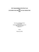
5.2.3 External dimensions
In open sections, the tolerances on external
dimensions of internal elements bounded by two
corner radii as shown inFigure1 shall be given
inTable1.
Table1 — Internal elements of open sections
The tolerances on external dimensions of outstand
elements bounded by a corner radius and a free end,
as shown inFigure2, shall be given inTable2.
Table2 — Outstand elements
5.2.4 Length
The length of a member shall not deviate from its
specified length by more than ± 3mm.
Wall
thickness
Permitted deviations for nominal plate
dimensions B
≤≤ 50 >50 ≤≤ 100 > 100 ≤≤ 200 > 200
mm mm mm mm mm
<3 ±0.75 ±1.0 ±1.25 ±2.0
≥ 3 <6 ±1.0 ±1.25 ±1.5 ±2.5
≥ 6 <8 ±1.25 ±1.5 ±1.75 ±3.0
NOTEIn a range of proprietary sections having varying
thicknesses, manufacturers usually quote nominal dimensions.
Because of rolling techniques the exact measurements vary
with the thickness and should be ascertained when checking
dimensional tolerances.
Figure1 — Internal element of open
section
Figure2 — Outstand element
Condition Thickness Nominal
plate
dimensions
C
Permitted
deviation
mm mm mm
Milled edge <3 ≤ 110 ±2.0
≥ 3 <8 ≤ 110 ±3.0
Sheared
edge
<3 ≤ 110 ±1.0
≥ 3 <8 ≤ 110 ±1.75
NOTEIn a range of proprietary sections having varying
thicknesses, manufacturers usually quote nominal dimensions.
Because of rolling techniques, the exact measurements vary
with the thickness and should be ascertained when checking
dimensional tolerances.
BS5950-7:1992
© BSI 12-1998
9
Section 5
5.2.5 Angular tolerances
The angle between adjacent elements of a section
shall not deviate from the specified angle by more
than ± 1°.
5.2.6 Straightness
The deviation e of a member from straightness (or
its intended shape) shall not exceed3mm or L/500,
whichever is more (seeFigure3).
In the case of complex cross sections, such as
markedly asymmetric sections, the permitted
deviations from straightness shall be agreed
between the designer and the manufacturer.
5.2.7 Angle of twist
The angle of twist shall not exceed1°/m of length.
In the case of complex cross sections the permissible
angle of twist shall be agreed at the time of enquiry
and order.
5.2.8 Compound members
Dimensional tolerances for compound members
made up from two or more sections and built-up
structural elements, such as lattice girders, shall be
agreed between the designer and the fabricator or
manufacturer.
5.3 Dimensional tolerances: profiled
sheets
5.3.1 Thickness
The thickness tolerances shall be as given in the
relevant British Standard for the steel used in the
manufacture of the profiled sheet.
5.3.2 Length
The length of a sheet shall not deviate from its
intended length by more than ± 5mm, except where
different tolerances are agreed in advance between
the designer and the manufacturer.
NOTE1Where sheets are situated between adjacent
components, it may be necessary to specify zero positive
tolerances.
NOTE2For very long sheets larger tolerances may be
appropriate.
5.3.3 Out-of-squareness
The deviation e of a profiled sheet from squareness,
measured at the orthogonal projection of a
transverse end onto a longitudinal edge
(seeFigure4), shall not exceed3mm.
5.3.4 Straightness
The deviation from straightness e, including any
parallel bulging (seeFigure5) of the longitudinal
edges of a profiled sheet shall not exceed2mm/m of
length up to a maximum of 10mm.
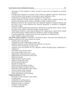
5.3.5 Bulging or contraction
The contraction or bulging e (seeFigure6) over the
length of a profiled sheet shall not exceed10.0mm
for profiles not exceeding55mm in depth,
and12.5mm for profiles greater than55mm in
depth.
Figure3 — Deviation from straightness for
cold formed sections
Figure4 — Deviation from squareness
Figure5 — Deviation from straightness
for profiled sheets
BS5950-7:1992
10
© BSI 12-1998
5.3.6 Dimensions of profiled sheets
For sheets with a nominal thickness of0.35mm
to1.2mm, the deviations of the profile dimensions
given inFigure7 shall not exceed the permitted
deviations given inTable3, except where different
tolerances are agreed in advance between the
designer and the manufacturer.
Table3 — Profiled sheets
Tolerances for material outside this range of
thickness shall be agreed between the designer and
the manufacturer.
Profile dimension Permitted deviation
Cover width W ±5 mm
Profile depth D +2 mm or –1 mm
Flange width B ±2 mm
Figure6 — Bulging and contraction of a profiled sheet
Figure7 — Profiled sheet
BS 5950-7:1992
© BSI 12-1998
11
Appendix A General
recommendations for steelwork
tenders and contracts
Reference should be made to appendix A of
BS5950-2:1985 which gives recommendations for
general information. When drawing up a contract
those points relevant to structures in cold formed
sections and profiled sheets should be considered.
If the use of a special cold formed section or profiled
sheet is being considered the manufacturer should
be consulted to determine optimum ordering
quantities.
BS5950-7:1992
© BSI 12-1998
12
Publication(s) referred to
BS639, Specification for covered carbon and carbon manganese steel electrodes for manual metal-arc
welding.
BS641, Dimensions of small rivets for general purposes (obsolescent).
BS1140, Specification for resistance spot welding of uncoated and coated low carbon steel.
BS1449, Steel plate, sheet and strip.
BS1449-1, Carbon and carbon-manganese plate, sheet and strip.
BS2901, Specification for filler rods and wires for gas-shielded arc welding.
BS2901-1, Ferritic steels.
BS2989, Specification for continuously hot-dip zinc coated and iron-zinc alloy coated steel of structural
qualities: wide strip, sheet/plate and slit wide strip.
BS3692, Specification for ISO metric precision hexagon bolts, screws and nuts. Metric units.
BS4174, Specification for self-tapping screws and metallic drive screws.
BS4190, Specification for ISO metric black hexagon bolts, screws and nuts.
BS4320, Specification for metal washers for general engineering purposes. Metric series.
BS4395, Specification for high strength friction grip bolts and associated nuts and washers for structural
engineering.
BS4604, Specification for the use of high strength friction grip bolts in structural steelwork. Metric series.
BS4620, Specification for rivets for general engineering purposes.
BS4933, Specification for ISO metric black cup and countersunk head bolts and screws with hexagon nuts.
BS5135, Specification for welding of carbon and carbon manganese steels.
BS5427, Code of practice for performance and loading criteria for profiled sheeting in building.
BS5493, Code of practice for protective coating of iron and steel structures against corrosion.
BS5531, Code of practice for safety in erecting structural frames.
BS5950, Structural use of steelwork in building.
BS 5950-1, Code of practice for design in simple and continuous construction: hot rolled sections
4)
.
BS 5950-2, Specification for materials, fabrication and erection: hot rolled sections.
BS 5950-3, Design in composite construction.
BS 5950-3.1, Code of practice for design of simple and continuous composite beams.
BS 5950-4, Code of practice for design of floors with profiled steel sheeting.
BS 5950-5, Code of practice for design of cold formed sections.
BS 5950-6, Code of practice for design of light gauge profiled sheeting.
BS 5950-8, Code of practice for fire resistant design
4)
.
BS6084, Method of test for comparison of prefabrication primers by porosity rating in arc welding.
BS6363, Specification for welded cold formed steel structural hollow sections.
BS6830, Specification for continuously hot-dip aluminium/zinc alloy coated cold rolled carbon steel flat
products.
BS EN10002-1, Tensile testing of metallic materials.
BS EN10002-1, Method of test at ambient temperature.
BS EN10025, Specification for hot rolled products of non-alloy structural steels and their technical delivery
conditions.
BS EN10130, Specification for cold rolled low carbon steel flat products for cold forming: technical delivery
conditions.
BS EN10142, Specification for continuous hot-dip zinc coated low carbon steel sheet and strip for cold
forming: technical delivery conditions.
DD24, Recommendations for methods of protection against corrosion on light section steel used in building.
PD6484, Commentary on corrosion at bimetallic contacts and its alleviation.
4)
Mentioned in the foreword only.
BS5950-7:1992
© BSI 12-1998
GS28, Safe errection of structures. HSE Guidance Note28. The Health and Safety Executive.
HMSO publication
5)
.
GS28-1, Initial design and planning.
GS28-2, Site management and procedures.
GS28-3, Working places and access.
GS28-4, Legislation and training.
ECCS41, European Recommendations for Steel Construction: Good practice in steel cladding and roofing.
Published by the European Convention for Constructional Steelwork. Available from the Steel Construction
Institute, Silwood Park, Buckhurst Road, Ascot, Berkshire SL5 7QN.
5)
Available from HMSO,49 High Holborn, London WC1V6HB (for personal callers) or by post from HMSO Publications Centre,
PO276, London SW185DT.
BSI
389 Chiswick High Road
London
W4 4AL
|
|
|
|
|
|
|
|
|
|
|
|
|
|
|
|
|
|
|
|
|
|
|
|
|
|
|
|
|
|
|
|
|
|
|
|
|
|
|
|
|
|
|
|
|
|
|
|
|
|
|
|
|
|
|
|
|
|
|
|
|
|
|
|
|
|
|
|
|
|
|
|
|
|
|
|
|
|
|
|
|
|
|
|
|
|
|
|
|
|
|
|
|
|
|
|
|
|
|
|
|
|
|
|
|
|
|
|
|
|
|
|
|
|
|
|
|
|
|
|
|
|
|
|
|
|
|
BSI Ð British Standards Institution
BSI is the independent national body responsible for preparing British Standards. It
presents the UK view on standards in Europe and at the international level. It is
incorporated by Royal Charter.
Revisions
British Standards are updated by amendment or revision. Users of British Standards
should make sure that they possess the latest amendments or editions.
It is the constant aim of BSI to improve the quality of our products and services. We
would be grateful if anyone finding an inaccuracy or ambiguity while using this
British Standard would inform the Secretary of the technical committee responsible,
the identity of which can be found on the inside front cover. Tel: 020 8996 9000.
Fax: 020 8996 7400.
BSI offers members an individual updating service called PLUS which ensures that
subscribers automatically receive the latest editions of standards.
Buying standards
Orders for all BSI, international and foreign standards publications should be
addressed to Customer Services. Tel: 020 8996 9001. Fax: 020 8996 7001.
In response to orders for international standards, it is BSI policy to supply the BSI
implementation of those that have been published as British Standards, unless
otherwise requested.
Information on standards
BSI provides a wide range of information on national, European and international
standards through its Library and its Technical Help to Exporters Service. Various
BSI electronic information services are also available which give details on all its
products and services. Contact the Information Centre. Tel: 020 8996 7111.
Fax: 020 8996 7048.
Subscribing members of BSI are kept up to date with standards developments and
receive substantial discounts on the purchase price of standards. For details of
these and other benefits contact Membership Administration. Tel: 020 8996 7002.
Fax: 020 8996 7001.
Copyright
Copyright subsists in all BSI publications. BSI also holds the copyright, in the UK, of
the publications of the international standardization bodies. Except as permitted
under the Copyright, Designs and Patents Act 1988 no extract may be reproduced,
stored in a retrieval system or transmitted in any form or by any means ± electronic,
photocopying, recording or otherwise ± without prior written permission from BSI.
This does not preclude the free use, in the course of implementing the standard, of
necessary details such as symbols, and size, type or grade designations. If these
details are to be used for any other purpose than implementation then the prior
written permission of BSI must be obtained.
If permission is granted, the terms may include royalty payments or a licensing
agreement. Details and advice can be obtained from the Copyright Manager.
Tel: 020 8996 7070.