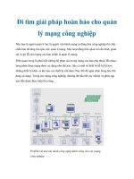
Mạng công cộng PSTN ( public service Telecom Network)
Bạn đang xem bản rút gọn của tài liệu. Xem và tải ngay bản đầy đủ của tài liệu tại đây (650.13 KB, 46 trang )
The University of Texas at Dallas
Erik Jonsson School of
Engineering & Computer Science
c
C. D. Cantrell (08/2010)
THE PUBLIC SWITCHED TELEPHONE NETWORK
Notes prepared for EEDG/CE 6345
by
Professor Cyrus D. Cantrell, P.E.
August–December 2010
THE UNIVERSITY OF TEXAS AT DALLAS
Erik Jonsson School of Engineering
and Computer Science
c
C. D. Cantrell (08/2004)
THE ANALOG TELEPHONE SYSTEM
• In use over wide areas until recently in some countries
Still widely used for connections to end users in North America
The local subscriber network reaches more users than any other network
Represents ∼ 90% of the net worth of the local Bell companies
• Precursor of the modern (mostly digital) PSTN
Services offered by long-established telephone companies are strongly
influenced by the history of the analog network
Regulatory environment
You have to understand the old analog network before you can understand
why we are where we are with digital networks
THE UNIVERSITY OF TEXAS AT DALLAS
Erik Jonsson School of Engineering
and Computer Science
S. D. Personick, Proc. IEEE 81, 1549–1557 (1993)
THE ANALOG TELEPHONE SYSTEM
THE UNIVERSITY OF TEXAS AT DALLAS
Erik Jonsson School of Engineering
and Computer Science
c
C. D. Cantrell (08/2004)
THE ANALOG SUBSCRIBER LOOP (1)
• Transmission media
Single wire with earth return
◦ Vulnerable to currents induced by atmospheric electric-field variations
along the wire, ground loops, and variable ground resistance
A differential signal transmitted on a wire pair
◦ Common-mode rejection with proper matching and balanced detection
◦ Uninsulated open wire pair
◦ Twisted pair
No. 22 AWG copper wire (ρ
L
≈ 16.5 Ω/1000 feet)
Wires are called “tip” (+) and “ring” (−) (terminology comes from
phone plugs used in manual switching)
Closed, balanced loop not referenced to earth ground
Bandwidth: 180 Hz to 3.2 kHz (at 3 dB points)
Multipair cable
/>THE PHONE LINE
A RELAY
200 Ohms Telephone . Subscriber
Exchange .
. TIP +
~~~~~~~ o o
|5H| .
||.
+||.
| . No 22 AWG wire
- 48V DC | . up to 10 Miles Long
| .
- A RELAY | .
-| 200 Ohms | .
| | .
| | . RING -
~~~~~~~ | o o
5H | | .
Audio 2uF | 2uF | .
coupling 250V 250V
Capacitors
||
o \ |
|
A RELAY Contacts |
|
o \
The University of Texas at Dallas
Erik Jonsson School of
Engineering & Computer Science
c
C. D. Cantrell (08/2004)
THE ANALOG SUBSCRIBER LOOP (2)
• Power supply
48 V DC, supplied by batteries located in the central (i.e., end) office
• Full-duplex communication
Talk and listen simultaneously
◦ A simple implementation requires 2 pairs (1 transmit and 1 receive)
Too expensive for widespread residential use
◦ Solution: Use 1 pair for both transmit and receive functions between
subscriber and central office
Sidetone: Some, but not too much, of the transmitted signal must be
fed back into the handset receiver
Partial cancellation achieved by appropriate phasing
Loop compensation adjusts audio level to −9 dBm (averaged)
The University of Texas at Dallas
Erik Jonsson School of
Engineering & Computer Science
c
C. D. Cantrell (09/2006)
CENTRAL OFFICE BATTERIES
THE UNIVERSITY OF TEXAS AT DALLAS
Erik Jonsson School of Engineering
and Computer Science
c
C. D. Cantrell (08/2004)
THE ANALOG SUBSCRIBER LOOP (3)
• Signaling at the handset
Call alerting at receiving telephone
◦ 90 V RMS @ 20 Hz, superimposed on DC
Loop-start signaling
◦ Taking a telephone off-hook makes current flow in the subscriber loop
◦ When a telephone goes off-hook to initiate a call:
The central office propagates dial tone to the telephone
◦ When a telephone goes off-hook to receive a call:
The central office cancels the ring signal
Address signaling
◦ Pulse dialing
The loop is interrupted (at ∼.1 s intervals) a number of times equal
to the digit being dialed, or 10 times for 0 (in the US)
◦ DTMF
Introduced to permit signaling across microwave links
THE UNIVERSITY OF TEXAS AT DALLAS
Erik Jonsson School of Engineering
and Computer Science
/>DTMF PAD AND FREQUENCIES
(Low ____ ____ ____ ____
Group)| |||||||
697Hz >| 1 | | 2 | | 3 | | A |
|____| |____| |____| |____|
____ ____ ____ ____
||||||||
770Hz >| 4 | | 5 | | 6 | | B |
|____| |____| |____| |____|
____ ____ ____ ____
||||||||
825Hz >| 7 | | 8 | | 9 | | C |
|____| |____| |____| |____|
____ ____ ____ ____
||||||||
941Hz >| * | | 0 | | # | | D |
|____| |____| |____| |____|
^^^^
1209Hz 1336Hz 1477Hz 1633Hz
(High Group)
THE UNIVERSITY OF TEXAS AT DALLAS
Erik Jonsson School of Engineering
and Computer Science
c
C. D. Cantrell (08/2004)
THE ANALOG CENTRAL OFFICE
• Addressing (North American system)
972 − 883
exchange
− 2111
station
Does not apply to 8xx, 9xx or WATS numbers
• Space-division switching and switch control
Step-by-step (uniselector plus bi-motional selectors plus Strowger switch)
◦ An exchange supports 10,000 stations with 4-digit addresses
The 10,000-number “block” is still the unit of PSTN addressing
◦ Combines switching with direct progressive control
Crossbar switch
◦ Selective, multi-unit, two-stage relay
Selecting units are horizontal bars and attached wire fingers
Entire address is received before a path through the switch is selected
Separates control from switching
THE UNIVERSITY OF TEXAS AT DALLAS
Erik Jonsson School of Engineering
and Computer Science
tech sxs.html
STEP-BY-STEP SWITCHING
THE UNIVERSITY OF TEXAS AT DALLAS
Erik Jonsson School of Engineering
and Computer Science
survey chapter 6.html
CROSSBAR SWITCH MECHANISM
THE UNIVERSITY OF TEXAS AT DALLAS
Erik Jonsson School of Engineering
and Computer Science
c
C. D. Cantrell (08/2004)
ANALOG INTEROFFICE TRUNKS
• Small cities have one central office; large cities have multiple CO’s
Signal attenuation (∼ 3 dB/3.5 mi) becomes an issue for total path lengths
greater than about 12 mi
◦ Amplification is required for long links
◦ Amplification is not feasible on a wire pair carrying full-duplex signals
◦ Conversion between a two-wire channel and a four-wire channel is
accomplished at the CO using a hybrid
Hierarchical network architecture:
◦ Design a combination of direct interoffice trunks and tandem (trunk-to-
trunk) switches to minimize call blocking probability for a given total
cost and average traffic pattern
Interoffice trunks:
◦ Originally open-wire, then multipair cables (common until optical fiber)
◦ Later: 12 voice channels frequency-multiplexed onto one pair
◦ Still later: Coaxial cable, carrying subcarrier-multiplexed signals
THE UNIVERSITY OF TEXAS AT DALLAS
Erik Jonsson School of Engineering
and Computer Science
/>2-WIRE/4-WIRE HYBRID
THE UNIVERSITY OF TEXAS AT DALLAS
Erik Jonsson School of Engineering
and Computer Science
William Stallings, Data and Computer Communications, 6th Edition
FREQUENCY-DIVISION MULTIPLEXING (TX)
Subcarrier modulator
f
1
m
1
(t)
Subcarrier modulator
f
2
Subcarrier modulator
f
n
Transmitter
f
c
m
2
(t)
s(t)
•
•
•
•
•
•
m
n
(t)
s
1
(t)
s
2
(t)
s
n
(t)
m
b
(t)
FDM signal
Composite baseband
modultating signal
THE UNIVERSITY OF TEXAS AT DALLAS
Erik Jonsson School of Engineering
and Computer Science
William Stallings, Data and Computer Communications, 6th Edition
FREQUENCY-DIVISION MULTIPLEXING (SPECTRUM)
Spectrum of composite signal using subcarriers at 64 kHz, 68 kHz, and 72 kHz
f
60 kHz
Lower
sideband, s
1
(t)
64 kHz 68 kHz 72 kHz
Lower
sideband, s
2
(t)
Lower
sideband, s
3
(t)
THE UNIVERSITY OF TEXAS AT DALLAS
Erik Jonsson School of Engineering
and Computer Science
William Stallings, Data and Computer Communications, 6th Edition
FREQUENCY-DIVISION MULTIPLEXING (RX)
Bandpass filter, f
1
•
•
•
s
1
(t)
Main
Receiver
s(t)
m
b
(t)
FDM signal
Demodulator, f
1
m
1
(t)
Bandpass filter, f
2
s
2
(t)
Demodulator, f
2
m
2
(t)
Bandpass filter, f
n
s
n
(t)
Demodulator, f
n
m
n
(t)
Composite baseband
signal
THE UNIVERSITY OF TEXAS AT DALLAS
Erik Jonsson School of Engineering
and Computer Science
William Stallings, Data and Computer Communications, 7th Edition
FDM CARRIER STANDARDS
North American and International FDM Carrier Standards
Number of voice
channels
Bandwidth Spectrum AT&T ITU-T
12 48 kHz 60–108 kHz Group Group
60 240 kHz 312–552 kHz Supergroup Supergroup
300 1.232 MHz 812–2044 kHz Mastergroup
600 2.52 MHz 564–3084 kHz Mastergroup
900 3.872 MHz
8.516–12.388
MHz
Supermaster
group
N × 600
Mastergroup
multiplex
3,600 16.984 MHz
0.564–17.548
MHz
Jumbogroup
10,800 57.442 MHz
3.124–60.566
MHz
Jumbogroup
multiplex
THE UNIVERSITY OF TEXAS AT DALLAS
Erik Jonsson School of Engineering
and Computer Science
c
C. D. Cantrell (08/2004)
ANALOG LONG-DISTANCE TECHNOLOGY (1)
• Transmission media
Wire pair (New York–Chicago, 1892)
◦ Vacuum-tube amplifiers introduced in 1914
Coaxial cable, carrying subcarrier-multiplexed signals
◦ 1941: First installation of coaxial cable in the network was between
Minneapolis, MN, and Stevens Point, WI (480 voice channels)
First practical coaxial cable was invented at AT&T in 1929
Later: Microwave radio links using subcarrier multiplexing
• Echo cancellation necessary
• Wide-area network architecture
Mostly hierarchical
Some high-usage trunks between end offices
Fully interconnected core (class 1 switches)
THE UNIVERSITY OF TEXAS AT DALLAS
Erik Jonsson School of Engineering
and Computer Science
John Bellamy, Digital Telephony, 2nd Edition
BELL PUBLIC NETWORK HIERARCHY, 1982
Switch Functional No. in No. in Total
Class Designation Bell System Independents
1 Regional center 10 0 10
2 Sectional center 52 0 67
3 Primary center 148 20 168
4 Toll center 508 425 933
5 End office 9803 9000 18,803
THE UNIVERSITY OF TEXAS AT DALLAS
Erik Jonsson School of Engineering
and Computer Science
c
C. D. Cantrell (08/2004)
ANALOG LONG-DISTANCE TECHNOLOGY (2)
• Disadvantages
Signal degradation as a result of amplification
◦ Increased noise figure
◦ Distortion due to nonlinearities
Phase-to-amplitude conversion
Intermodulation distortion
THE UNIVERSITY OF TEXAS AT DALLAS
Erik Jonsson School of Engineering
and Computer Science
c
C. D. Cantrell (08/2004)
INTRODUCTION OF DIGITAL TECHNOLOGY
• Motivations
Increased traffic capacity on interoffice trunks
Improved signal quality
• T-1 carrier (1961)
Developed at Bell Laboratories
◦ Signal format is DS-1
◦ T-1 is the specific electrical implementation
Multiplexes 24 (single-duplex) voice channels onto one wire pair
◦ Synchronous
One voice channel occupies a specific “slot” in the DS-1 frame
Demultiplexing is easy
◦ Problem: Repeaters required every 2 km for “3-R” regeneration
Retiming, regeneration of the signal, and retransmission
THE UNIVERSITY OF TEXAS AT DALLAS
Erik Jonsson School of Engineering
and Computer Science
c
C. D. Cantrell (02/2000)
DIGITAL TRANSMISSION OF ANALOG SIGNALS
• Example: North American PSTN
• The analog time-varying voltage produced by sound waves impinging on a
microphone travels over a twisted pair of copper wires to an end office
The time-varying voltage is sampled at intervals of 125 µs (8000 s
−1
)
◦ The result is a pulse amplitude modulation signal
◦ Original baseband signal can be reconstructed from PAM sequence
◦ Could transmit the PAM sequence on trunk lines, but then we’d have
distortion and noise again
The PAM signal is quantized and encoded digitally using 8 bits/sample
◦ The result is a pulse code modulation signal
◦ Quantization noise is an unavoidable side effect of digitization
• The octets from 24 different logical channels are inserted into a DS-1 frame
and transmitted over a trunk line at a rate of 8000 frames/second
End
office
Toll
office
End
office
Analog
(local
loop)
Bit-serial TDM digital
(telephone
company
trunks)
Analog
(local
loop)
PCM
Codec
PCM
Codec
Customer premises
equipment
Customer premises
equipment
∆f ≤ 3.3 kHz
∆f ≤ 3.3 kHz
Datapath for a telephone call via the PSTN (U.S.)
THE UNIVERSITY OF TEXAS AT DALLAS
Erik Jonsson School of Engineering
and Computer Science
c
C. D. Cantrell (01/2000)
PULSE AMPLITUDE MODULATION (PAM)
t
t
1
t
2
t
3
t
4
t
5
t
6
t
7
Sampling times