UWB Antenna TOH ppt
Bạn đang xem bản rút gọn của tài liệu. Xem và tải ngay bản đầy đủ của tài liệu tại đây (428.48 KB, 4 trang )
2172 IEEE TRANSACTIONS ON ANTENNAS AND PROPAGATION, VOL. 57, NO. 7, JULY 2009
Communications
A Planar UWB Antenna With a Broadband Feeding
Structure
Wee Kian Toh, Zhi Ning Chen, and Xianming Qing
Abstract—A planar antenna with a broadband feeding structure is pre-
sented and analyzed for ultrawideband applications. The proposed antenna
consists of a suspended radiator fed by an n-shape microstrip feed. Study
shows that this antenna achieves an impedance bandwidth from 3.1–5.1
GHz (48%) for a reflection of coefficient of
, and an
average gain of 7.7 dBi. Stable boresight radiation patterns are achieved
across the entire operating frequency band, by suppressing the high order
mode resonances. This design exhibits good mechanical tolerance and man-
ufacturability.
Index Terms—Broadband antennas, microstrip patch antennas, sus-
pended plate antennas, ultrawideband (UWB) antennas.
I. INTRODUCTION
A low profile and embeddable unidirectional antenna is required for
certain ultrawideband (UWB) [1] communication, imaging, localiza-
tion, and radar applications. The lower and upper UWB spectrums are
3.1–4.8 GHz (43%) and 6.0–10.6 GHz (55%), respectively. The ex-
isting broadband directional antennas, such as the Vivaldi [2], log-pe-
riodic, cavity-backed, waveguide, horn, and dish antennas, cover the
entire 3.1–10.6 GHz band (109%). However, they are electrically large,
and have a high profile in the direction of wave propagation. Omni- and
bi-directional antennas, suchas the planar monopoles [3]–[5], disc cone
[6], and slot antennas [7], have a low gain and back radiation pattern,
therefore they are not suitable for sectorial or unidirectional commu-
nication. Also, it is a challenge to maintain a stable radiation pattern
across the whole frequency band, since the radiation aperture is fre-
quency dependent.
To lower the Q-value for increasing the impedance bandwidth of
the patch antenna, the dielectric substrate is replaced by air, the patch
is usually suspended at a height of
, where
is the free
space wavelength. However, when the height of the patch antenna
is increased, the high inductance [8] from a long feeding probe
makes it difficult to achieve impedance matching. To broaden the
impedance bandwidth, notches and slots have been employed, such
as the E-shaped [9], U-slot patches [10], and planar electric dipole
with shorted patches [11], to compensate the large input inductance.
Furthermore, other broadband feeding techniques such as the aperture
coupled feed [12], L-probe feed [13], center slot feed [14], suspended
probe feed [15], and folded feed [16] have been used. Although a
broadband impedance matching is achieved, the radiation patterns
of such patch antennas at the higher frequency are degraded by the
occurrence of high order modes. Consequently, the co-polarization
Manuscript received January 15, 2008; revised January 15, 2008. First pub-
lished May 02, 2009; current version published July 09, 2009.
The authors are with the RF & Optical Department, Institute for Infocomm
Research, Singapore 138632, Singapore (e-mail: ).
Color versions of one or more of the figures in this communication are avail-
able online at .
Digital Object Identifier 10.1109/TAP.2009.2021968
radiation patterns in the E-plane are squinted, while the cross-polar-
ization radiation levels in the H-plane are increased. Therefore, the
boresight gain and half-power beamwidth are inconsistent across the
broad operating bandwidth. This feature limits the applications of
patch antennas in UWB systems requiring stable radiation patterns,
such as the beacon or requestor for location systems.
In this communication, a planar unidirectional UWB antenna with
non-squinting radiation patterns and a relatively constant gain profile
(
1.5 dBi) is presented. Using a single patch radiator and a simple
n-shape feeding structure, broadband impedance matching is achieved.
II. A
NTENNA STRUCTURE
The schematic diagram of a single-element planar antenna is shown
in Fig. 1. It consists of a radiator and a feeding structure. The radiator
measures 22
30 mm, and is positioned at a height of
.
The n-shape microstrip feeding line is excited by a 50
SMA con-
nector, while the other end is connected to the radiator through a ver-
tical strip. Thewidth of the feeding line is 5 mm wide (89
), suspended
at a height of
, using Styrofoam material with a relative
permittivity of
. The antenna is designed to operate in the lower
UWB band of 3.1 to 4.8 GHz. At 3.0 GHz, the free space wavelength
. The radiator structure measures
,
and the ground plane is
. The copper plates are 0.5 mm thick.
The 7.5 mm wide (70
)
feeding line is optimized to improve the
impedance matching. A gradual 50-70-89
impedance transforma-
tion provides a broadband impedance matching between the feeding
line and the patch.
III. R
ESULTS
All the simulations in this communication were conducted using
a full-wave simulator IE3D. The antenna was subsequently pro-
totyped for experimental verification. The reflection coefficient
measurement was taken using a HP8510C vector network analyzer.
A broad impedance bandwidth covering from 3.1–5.1 GHz (48%) for
is shown in Fig. 2. The simulated resonances are in
good agreement with those of the measurement.
The measured radiation patterns at 3.0 , 4.0, and 5.0 GHz are shown
in Figs. 3(a)–(c). The maximum H-plane cross-polarization levels grad-
ually increase with increasing frequency, and peaked at
.
At 5.0 GHz, the increase in cross-polarization levels is due to the oc-
currences of high order mode resonances. Nonetheless, the radiation
patterns remain stable, and there is no squinting from 3.0–5.0 GHz.
Fig. 4 shows the maximum co-polarizations gain profile, which is also
directed at the boresight, and the maximum cross-polarization on the
E- and H-planes. An average gain of 7.7 dBi is achieved with
1.5 dBi
of gain fluctuation. As the H-plane cross-polarization levels increase,
the co-polarization gain decreases. Fig. 5 shows the 3-dB beamwidth
plot for both the E- and H-planes, varying from 40
to 65
and 70 to
90
respectively.
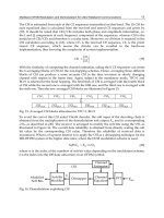
Fig. 6 shows the simulated boresight gain and reflection coefficient
characteristics for the antenna, when the ground plane is reduced
from infinity to 40
40 mm. The measured gain profile on a 100
100 mm ground plane agrees well with that of the simulation,
comparing Fig. 4 and Fig. 6. Both readings show a peak gain of
9.4 dBi at 3.75 GHz, and a decreasing gain of 6.5 dBi at 5.0 GHz,
with less than 0.4 dBi of differences. The impedance matching
remains unchanged, when the ground plane is varied from infinity
0018-926X/$25.00 © 2009 IEEE
Authorized licensed use limited to: Phan Phuong. Downloaded on October 6, 2009 at 04:45 from IEEE Xplore. Restrictions apply.
IEEE TRANSACTIONS ON ANTENNAS AND PROPAGATION, VOL. 57, NO. 7, JULY 2009
2173
Fig. 1. Schematic diagram antenna.
to 60 60 mm ( at 3.0 GHz). The corresponding
peak gain varies from 8.0 dBi for an infinitely large ground plane,
to 9.5 dBi for a 100
100 mm ground plane, and 8.0 dBi for
a60
60 mm ground plane. The 80 80 mm ground plane
provides the most stable gain performance.
IV. A
NALYSIS
The lower and higher resonant frequencies of this antenna are
mainly determined by two components, (a) the length of the radiator
, and (b) the height of the vertical strip. The resonant
frequencies are estimated by
(1)
Fig. 2. Measured and simulated reflection coefficient .
where is in GHz,
and
are in mm. Fig. 7(a) and (b)
depict the instantaneous current distribution and vector plot of a
cycle, at 3.4 and 4.6 GHz, respectively. The two current minima
Authorized licensed use limited to: Phan Phuong. Downloaded on October 6, 2009 at 04:45 from IEEE Xplore. Restrictions apply.
2174 IEEE TRANSACTIONS ON ANTENNAS AND PROPAGATION, VOL. 57, NO. 7, JULY 2009
Fig. 3. Measured radiation patterns at (a) 3.0 GHz, (b) 4.0 GHz, and
(c) 5.0 GHz.
of the current distribution on the patch depict the half-wavelength
resonant frequencies. At the lower resonance, the vertical strip is
considered as part of the radiating element. The dash-lines depict the
half-wavelength resonant. Therefore, the effective radiating length is
43 mm, and
. The difference between the estimated
and measured lower resonating frequencies is 2.5%. At the higher
resonance, the radiation on the vertical strip is substantially weaker
than that of at the lower resonance. Therefore, the effective radiating
length is 30 mm, and
. The difference between the
estimated and measured higher resonating frequencies is 5.2%. It is
validated that (1) could be used as design guidelines to estimate the
resonating frequencies for the proposed antenna. These guidelines
are not applicable when the height of the patch is raised from
to , when the two resonances and
are far apart from each other; where the coupling between the
n-shaped microstrip line and patch is reduced.
A parametric study of this antenna, by varying the length
and height of the n-shaped feeding line, and height
of the patch
Fig. 4. Measured maximum gain on the E- and H-planes.
Fig. 5. 3-dB beamwidth of the radiation patterns on the H- and E-planes.
Fig. 6. Simulated reflection coefficient and boresight gain performances
for various ground plane dimensions.
were conducted. The results are shown in Figs. 8 and 9. When
is in-
creased from 13–20 mm (53.8%), the impedance bandwidth is reduced
to 3.1–4.4 GHz (17.3%). The boresight gain is reduced, and begins to
squint after 4.3 GHz. This is due to the reduced coupling between the
n-shaped microstrip line and patch. When
is extended from
26–30 mm (15.3%), there are no changes to the gain performance, no
squinting, and the impedance matching remains at
.
Authorized licensed use limited to: Phan Phuong. Downloaded on October 6, 2009 at 04:45 from IEEE Xplore. Restrictions apply.
IEEE TRANSACTIONS ON ANTENNAS AND PROPAGATION, VOL. 57, NO. 7, JULY 2009
2175
Fig. 7. Instantaneous current distribution and vector plot of a cycle. (a) 3.4
GHz; (b) 4.6 GHz.
Fig. 8. Maximum gain, boresight gain, and reflection coefficient plots for con-
figurations A (original), B (extended patch height), and C (extended n-shaped
feed line), using simulator.
Fig. 9. Maximum gain, boresight gain, and reflection coefficient plots for con-
figurations D
,E , and F ,
using simulator with infinite ground plane.
Fig. 9 shows the impedance bandwidth and gain profile when height
( 20%), using infinite ground plane. It can be
seen that there are minimal changes to the impedance matching and
gain profile. Therefore this design has a good mechanical tolerance due
to the low Q value of the antenna. Furthermore, from Fig. 7(b), it is
seen that at the higher resonance, the current at the top radiator does
not have any cross-polarized component; hence beam squinting effect
from higher order modes at the higher frequency has been reduced.
V. C
ONCLUSION
A planar UWB antenna design using a broadband feeding technique
has been presented and discussed. This simple feeding structure cou-
pled with the radiator has suppressed high order mode resonances at
higher frequencies. Therefore it achieved a non-squinting broadside ra-
diation patterns across the broad operating bandwidth of 48%. The two
resonances have been explained, and a simple formula has been pro-
vided to estimate the resonating frequencies. This design has a high
mechanical tolerance.
REFERENCES
[1] First Report and Order Federal Communications Commission (FCC),
Feb. 2002.
[2] P. J. Gibson, “The Vivaldi aerial,” in
Eur. Microw. Conf., Oct. 1979,
pp. 101–105.
[3] N. P. Agrawall, G.Kumar, and K. P.Ray, “Wide-band planar monopole
antennas,” IEEE Trans. Antennas Propag., vol. 46, no. 2, pp. 294–295,
Feb. 1998.
[4] Z. N. Chen, “Broadband rolled monopole,” IEEE Trans. Antennas
Propag., vol. 51, no. 11, pp. 3175–3177, Nov. 2003.
[5] Z. N. Chen, M. Y. Chia, and M. J. Ammann, “Optimization and
comparison of broadband monopoles,” Proc. IEE Microw. Antennas
Propag., vol. 150, no. 6, pp. 429–435, Dec. 2003.
[6] X. Qing, Z. N. Chen, and M. Y. W. Chia, “UWB characteristics of disc
cone antenna,” in Proc. Int. Workshop on Antenna Technol. IWAT, Mar.
2005, pp. 97–100.
[7] Y. F. Liu, K. L. Lau, and C. H. Chan, “Experimental studies of printed
wide-slot antenna for wide-band applications,” IEEE Antennas Wire-
less Propag. Lett., vol. 3, pp. 273–275, 2004.
[8] P. S. Hall, “Probe compensation in thick microstrip patches,” Electron.
Lett., vol. 23, pp. 606–607, May 1987.
[9] F. Yang, X. Zhang, X. Ye, and Y. Rahmat-Samii, “Wide-band E-shaped
patch antennas for wireless communications,” IEEE Trans. Antennas
Propag., vol. 49, no. 7, pp. 1094–1100, Jul. 2001.
[10] T. Huynh and K. F. Lee, “Single-layer single patch wideband mi-
crowave antenna,” IEE Electron. Lett., vol. 31, no. 16, pp. 1310–1312,
Aug. 1995.
[11] K. M. Luk and H. Wong, “A new wideband unidirectional antenna,”
Int. J. Microw. Opt. Technol., vol. 1, no. 1, pp. 35–44, Jun. 2006.
[12] D. M. Pozar, “A microstrip antenna aperture coupled to a microstip
line,” Electron. Lett., vol. 21, pp. 49–50, Jan. 1985.
[13] K. M. Luk, C. L. Mak, Y. L. Chow, and K. F. Lee, “Broadband
microstrip patch antenna,” IEE Electron. Lett., vol. 34, no. 15, pp.
1442–1443, Jul. 1998.
[14] Z. N. Chen and M. Y. W. Chia, Broadband Planar Antennas: Design
and Applications. Hoboken, NJ: Wiley, Feb. 2006.
[15] N. Herscovici, “A wide-band single-layer patch antenna,” IEEE Trans.
Antennas Propag., vol. 46, pp. 471–474, Apr. 1998.
[16] Z. N. Chen and W. K. Toh, “Dual broadband folded antenna embedded
into access-point decices,” presented at the EuCAP 2006, Nov. 2006.
Authorized licensed use limited to: Phan Phuong. Downloaded on October 6, 2009 at 04:45 from IEEE Xplore. Restrictions apply.