Designation: B 9 – 90 (Reapproved 1998)e2 - Bronze Trolley Wire1 ppsx
Bạn đang xem bản rút gọn của tài liệu. Xem và tải ngay bản đầy đủ của tài liệu tại đây (75.11 KB, 7 trang )
Designation: B 9 – 90 (Reapproved 1998)
e2
Standard Specification for
Bronze Trolley Wire
1
This standard is issued under the fixed designation B 9; the number immediately following the designation indicates the year of original
adoption or, in the case of revision, the year of last revision. A number in parentheses indicates the year of last reapproval. A superscript
epsilon (e) indicates an editorial change since the last revision or reapproval.
e
1
NOTE—Table 4 was updated and Section 18 was added editorially in June 1998.
e
2
NOTE—Figure 1 was updated editorially in August 2002.
1. Scope
1.1 This specification covers round, grooved, and figure-9
deep-section grooved bronze trolley wire.
1.2 The bronze trolley wire may be made in any of the three
distinct alloys indicated in accordance with their increasing
conductivities: Alloy 40, Alloy 55, Alloy 80.
1.3 The values stated in inch-pound units are to be regarded
as the standard. The metric equivalents of inch-pound units
given in this standard may be approximate.
2. Ordering Information
2.1 Orders for material under this specification shall include
the following information:
2.1.1 Quantity of each size, section, and class,
2.1.2 Wire size: diameter in in. (see 5.1 and Table 1) or area
in circular mils (see 8.1 and Fig. 1 and Fig. 2),
2.1.3 Shape of section (see 1.1),
2.1.4 Alloy (see 1.2),
2.1.5 Package size (see 17.3),
2.1.6 Lagging, if required (see 17.1),
2.1.7 Relation between vertical axis of grooved wire and
axis of reel (see 17.1),
2.1.8 Size of arbor hole if other than 4-in. (102 mm) square
(see 17.2),
2.1.9 Special package marking, if required (see 17.4), and
2.1.10 Place of inspection (Section 15).
3. Material
3.1 The material shall be bronze of such nature and com-
position (Explanatory Note 1) as to secure, by proper treat-
ment, the qualities prescribed in this specification for the
finished wire.
ROUND WIRE
4. Tensile Properties
4.1 Round wire shall conform to the requirements as to
tensile properties prescribed in Table 1.
4.2 Tests on a specimen of round wire containing a joint
shall show at least 95 % of the tensile strength specified in
Table 1. Elongation tests shall not be made on specimens
containing joints.
4.3 Tension tests shall be made on representative samples.
The elongation shall be determined as the permanent increase
in length, due to the breaking of the wire in tension, measured
between gage marks placed originally 10 in. (254 mm) apart
upon the test specimen (Explanatory Note 2). The fracture shall
be between the gage marks and not closer than 1 in. (25.4 mm)
to either gage mark.
5. Dimensions and Permissible Variations
5.1 The size of round trolley wire shall be expressed as the
diameter of the wire in decimal fractions of an inch to the
nearest 0.1 mil (0.0001 in.) (0.0025 mm).
5.2 Wire shall be truly cylindrical in form. The diameter
shall not vary more than 6 1 % from that specified.
6. Twist Test
6.1 For the purpose of determining and developing defects
which may be prejudicial to the life of trolley wire, owing to its
peculiar service as compared to that of wire for other purposes,
round wire shall be subjected to the twist test described in 6.2.
Round wire shall not be considered satisfactory which does not
withstand, without breaking, at least the number of twists
prescribed in Table 2.
6.2 Three twist tests shall be made on specimens 10 in. (254
mm) in length between the holders of the testing machine. The
twisting machine shall be so constructed that there is a linear
motion of the tail stock with respect to the head. The twist shall
be applied not faster than 10 turns/min. All three specimens
shall be twisted to destruction and shall not reveal under test
any seams, pits, slivers, or surface imperfections of sufficient
magnitude to indicate inherent defects or imperfections in the
wire. At the time of fracture the wire shall twist with reason-
able uniformity.
1
This specification is under the jurisdiction of ASTM Committee B01 on
Electrical Conductors and is the direct responsibility of Subcommittee B01.04 on
Conductors of Copper and Copper Alloys.
Current edition approved Aug. 3, 1990. Published October 1990. Originally
published as B9–15T.Last previous edition B9–76(1990).
1
Copyright © ASTM International, 100 Barr Harbor Drive, PO Box C700, West Conshohocken, PA 19428-2959, United States.
GROOVED AND FIGURE-9 WIRE
7. Tensile Properties
7.1 Grooved and figure-9 wire shall conform to the appli-
cable requirements as to tensile properties prescribed in Table
3.
7.2 Tests on a specimen of grooved or figure-9 wire con-
taining a joint shall show at least 95 % of the tensile strength
specified in Table 3. Elongation tests shall not be made on
specimens containing joints.
7.3 The tension and elongation tests for grooved or figure-9
wire shall be made in the same manner as those on round wire
as described in 4.3.
8. Dimensions and Permissible Variations
8.1 The size of the trolley wire shall be expressed as the
nominal area of cross section in circular mils.
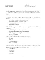
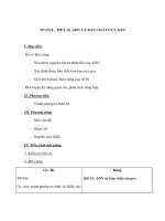
8.2 The standard sizes of grooved trolley wire shall be as
specified in Fig. 1.
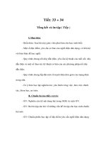
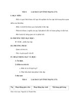
8.3 The standard size of figure-9 wire shall be as specified in
Fig. 2.
8.4 The weight in pounds per mile of grooved and figure-9
trolley wire calculated from the weight of a specimen not less
than 18 in. (460 mm) in length shall not vary more than 6 4%
from that specified in Fig. 1 for grooved wire, and Fig. 2 for
figure-9 wire.
8.5 Conformance of the trolley wire to the specified dimen-
sions shall be determined by taking the measurements shown in
Fig. 1 and Fig. 2 under the heading, “Dimensions for Inspec-
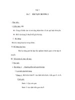
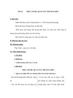
tion, in.” The shape of the groove shall be checked with the
appropriate “go” and “no-go” slip gages described in Fig. 3.
The gages shall be applied to the ends of the samples taken
from each reel. Samples shall be clean and the ends free from
burrs. The groove shall be considered as conforming to this
specification if the “go” gage can be pushed on the straightened
wire by hand and the “no-go” gage cannot be pushed on the
wire.
9. Sections
9.1 Standard sections of grooved trolley wire shall be
known as the “American Standard Grooved Trolley Wire
Sections” (the Standard Design of the American Transit Engi-
neering Association) shown in Fig. 1.
9.2 The standard section of figure-9 wire shall be as shown
in Fig. 2.
10. Twist Test
10.1 For the purpose of determining and developing defects
that may be prejudicial to the life of trolley wire, owing to its
peculiar service as compared to that of wire for other purposes,
grooved wire shall be subjected to the twist test described in
6.2. Grooved wire that does not withstand at least three twists
without breaking shall not be considered satisfactory. The twist
test shall be omitted for figure-9 wire.
ROUND, GROOVED, AND FIGURE-9 WIRE
11. Resistivity
11.1 Electrical resistivity shall be determined on represen-
tative samples by resistance measurements (Explanatory Note
3). At a temperature of 20°C the resistivity shall not exceed the
values prescribed in Table 4.
11.2 Lower resistivities in wires conforming to the physical
qualifications may be obtained by the use of special alloys.
12. Density
12.1 For the purpose of calculating mass, cross-sections,
etc., the density of the bronze (Explanatory Note 4) shall be
taken as 8.89 g/cm
3
(0.32117 lb/in.
3
) at 20°C (Explanatory Note
5).
13. Joints
13.1 No joints shall be made in the completed wire. Joints in
the wire and rods made prior to final drawings shall be in
accordance with the best commercial practice, and shall be
capable of meeting the tensile strength requirements in 4.2 or
7.2.
14. Workmanship, Finish, and Appearance
14.1 The wire shall be of uniform size, shape, and quality
throughout, and shall be free from all scale, flaws, splits, and
scratches not consistent with the best commercial practice.
15. Inspection
15.1 All tests governing the acceptance or rejection of the
wire, unless otherwise specified, shall be made at the place of
manufacture with apparatus furnished by the manufacturer and
in the presence of the purchaser or his representative, who shall
be furnished a copy of the tests. The manufacturer shall afford
the inspector representing the purchaser all reasonable facilities
to satisfy him as to the reliability of the results before the wire
is delivered. If the purchaser waives inspection, and if he so
elects at that time, he shall be furnished with a certified copy of
tests made by the manufacturer.
16. Rejection
16.1 Any reel of wire that fails to conform to the require-
ments prescribed in this specification may be rejected. Failure
TABLE 1 Tensile Requirements for Round Trolley Wire
Diameter Area Tensile Strength, min
Elongation
in 10 in.
(254 mm),
min, %
in. mm cmil mm
2
Alloys 40 and 55 Alloy 80
psi MPa psi MPa
0.5477 13.911 300 000 152.0 64 800 447 61 500 424 4.50
0.4600 11.648 211 600 107.0 69 000 476 65 000 448 3.75
0.4096 10.404 167 800 85.0 71 000 490 67 000 462 3.25
0.3648 9.266 133 100 67.4 73 000 503 69 000 476 2.75
0.3249 8.252 105 600 53.5 76 000 524 72 000 496 2.40
B 9 – 90 (1998)
e2
2
Nominal Size:
cmil 133 100 167 800 211 600 300 000 350 000
(mm
2
) (67.4) (85.0) (107.00) (152.0) (177.3)
Area (Explanatory Note 6):
cmil 137 900 167 300 212 000 299 800 351 200
in
2
0.1083 0.1314 0.1665 0.2355 0.2258
(mm
2
) (69.9) (84.7) (107.4) (151.9) (177.9)
Weight (Explanatory Note 6):
lb/mile
(kg/km)
2205
(621)
2674
(756)
3389
(955)
4792
(1350)
5612
(1581)
Dimensions for Inspection, in.
A
0.388
20.012
10.006
0.429
20.012
10.006
0.482
20.012
10.006
0.574
20.020
10.010
0.620
20.020
10.010
B 0.3926 0.007 0.430 6 0.008 0.482 6 0.009 0.574 6 0.011 0.6206 0.012
C 0.318 6 0.007
A
†
0.340 6 0.007 0.376 6 0.007 0.376 6 0.007 0.376 6 0.007
Dimensions for Inspection, mm
A
9.86
20.3048
10.1524
10.6
20.3048
10.1524
12.2
20.3048
10.1524
14.6
20.508
10.254
15.7
20.508
10.254
B 9.96 6 0.1778 10.9 6 0.2032 12.2 6 0.2286 14.6 6 0.2794 15.7 6 0.3048
C 8.08 6 0.1778 8.64 6 0.1778 9.55 6 0.1778 9.55 6 0.1778 9.55 6 0.1778
Dimensions for Reference, in.
D—radius 0.196 0.215 0.241 0.287 0.310
E
0.217
20.010
10.005
0.237
20.010
10.005
0.2676 0.010 0.267 6 0.010 0.267 6 0.010
F 0.200 0.220 0.250 0.250 0.250
G 0.031 0.047 0.063 0.127 0.156
H 0.005 0.005 0.005 0.005 0.005
J276 2° 27 6 2° 27 6 2° 27 6 2° 27 6 2°
K516 2° 51 6 2° 51 6 2° 51 6 2° 51 6 2°
L 78° 78° 78° 78° 78°
M—radius
0.015
20.005
10.010
0.015
20.005
10.010
0.015
20.005
10.010
0.015
20.005
10.010
0.015
20.005
10.010
Dimensions for Reference, mm
D—radius 4.98 5.46 6.12 7.29 7.84
E
5.51
20.234
10.127
6.02
20.254
10.127
6.786 0.254 6.78 6 0.254 6.78 6 0.254
F 5.08 5.59 6.35 6.35 6.35
G 0.7874 1.194 1.60 3.23 3.96
H 0.127 0.127 0.127 0.127 0.127
M—radius
0.381
20.127
10.254
0.381
20.127
10.254
0.381
20.127
10.254
0.381
20.127
10.254
0.381
20.127
10.254
A
†
Editorially corrected.
NOTE 1—Dimensions H is defined by two center lines of which the upper is the center line of the radius of the groove and the lower is the center line
of the groove.
FIG. 1 Standard Sections Grooved Trolley Wire
B 9 – 90 (1998)
e2
3
of 30 % of the number of reels ready for inspection at one time
shall be deemed sufficient cause for the rejection of the whole
lot.
Nominal Size, cmil 335 000
Area:
in.
2
(Explanatory Note 6)
0.2642
(mm
2
) (170.5)
cmil 336 400
Weight:
lb/mile (Explanatory Note 6)
5386
(kg/km) (1517)
Dimensions for Inspection
in. (mm)
A (at dimension N)
0.482
–0.012
10.006
12.2
–0.3048
10.0015
B
C
0.680 6 0.012
0.376 6 0.007
(17.3 6 0.3048)
(9.55 6 0.1778)
Dimensions for Reference
in. (mm)
D 0.235 (5.97)
D8—radius 0.275 (6.98)
D9—radius 0.960 (24.4)
E 0.267 6 0.010 (6.78 6 0.25)
F 0.250 (6.35)
G 0.093 (2.36)
H 0.005 (1.27)
J276 2° (27 6 2°)
K516 2° (51 6 2°)
L 78° (78°)
M—radius
0.015
–0.005
10.010
~
3.81
!
–0.127
10.254
N
P—radius
0.342
0.037 6 0.007
(8.69)
(0.9406 0.1778)
NOTE 1—Dimension H is defined by two center lines of which the upper is the center line of the radius of the groove and the lower is the center line
of the groove.
FIG. 2 Standard Section Figure-9 Deep-Section Grooved Trolley Wire
TABLE 2 Twist Test Requirements for Round Wire
Diameter Number
of
Twists
in. mm
0.5477 13.911 20
0.4600 11.684 23
0.4096 10.404 25
0.3648 9.266 27
0.3249 8.252 30
TABLE 3 Tensile Requirements for Grooved and Figure-9
Trolley Wire
Nominal
Area,
cmil
Tensile Strength, Minimum
Elongation
in 10 in.
(254 mm),
min, %
Alloys 40 and 55 Alloy 80
psi MPa psi MPa
Grooved:
350 000 62 500 431 59 500 410 4.00
300 000 64 800 447 61 500 424 4.00
211 600 69 000 476 65 000 448 3.25
167 800 71 000 490 67 000 462 2.75
133 100 73 000 503 69 000 476 2.25
Figure-9:
335 000 61 500 424 56 800 392 4.00
B 9 – 90 (1998)
e2
4
17. Packaging and Package Marking
17.1 All wire shall be shipped on substantial reels, suitable
for the weight of the wire handled, and shall be well protected
from injury. The diameter of the reel drums shall be sufficiently
large, not less than 30 in. (760 mm), to eliminate difficulty with
waves or kinks when the wire is strung. If reels are to be
lagged, it shall be so specified by the purchaser. The wire shall
be reeled with turns tightly together, in uniform layers, free
from kinks and crosses. The relation between the vertical axis
of grooved wire as finally strung and the axis of the reel shall
be as specified by the purchaser and shall be approximately
constant.
17.2 The ends of the wire shall be securely fastened to the
sides of the reel with no less than six staples. The staples shall
be at least 2 in. (50 mm) in length and made from wire not less
than 0.145 in. (3.68 mm) in diameter. Care shall be exercised
in stapling not to damage the surface of the exposed layer of
wire. All reels shall have the arbor holes reinforced with steel
plate at least
1
⁄
2
in. (12.5 mm) in thickness, and unless
otherwise specified, the arbor hole shall be a 4-in. (102 mm)
square hole.
17.3 The length or weight of the wire to be wound upon
each reel shall be agreed upon between the manufacturer and
the purchaser in placing individual orders.
17.4 Reels shall be marked legibly and indelibly with a
Dimension
Dimensions of Gage, in. (Except as Indicated)
For Trolley Wire of Nominal Size
133 100 cmil
For Trolley Wire of Nominal Size
167 800 cmil
For Trolley Wire of Nominal Sizes 211 600,
300 000, 335 000 and 350 000 cmil
Go No-Go Go No-Go Go No-Go
D
5
⁄
16
5
⁄
16
5
⁄
16
5
⁄
16
5
⁄
16
5
⁄
16
E 0.223 6 0.0005 0.207
–0.001
10.000
0.243 6 0.0005 0.227
–0.001
10.000
0.278 6 0.0005 0.257
–0.001
10.000
F 0.212 0.200 0.235 0.220 0.268 0.248
G 0.031 0.031 0.047 0.047 0.063 0.063
J 25° 29° 25° 29° 25° 29°
K 53° 53° 53° 53° 53° 53°
L 78° 82° 78° 82° 78° 82°
M–radius 0.010 6 0.002 0.010 6 0.002 0.010 6 0.002 0.010 6 0.002 0.010 6 0.002 0.010 6 0.002
N—radius
5
⁄
16
5
⁄
16
5
⁄
16
5
⁄
16
5
⁄
16
5
⁄
16
V
1
⁄
2
1
⁄
2
1
⁄
2
1
⁄
2
1
⁄
2
1
⁄
2
X 111111
Y 111111
Dimensions of Gage, mm
D 7.94 7.94 7.94 7.94 7.94 7.94
E 5.66 6 0.0127 5.26
–0.0254
10.000
6.176 0.0127 5.77
–0.0254
10.000
7.06 6 0.0127 6.53
–0.0254
10.000
F 5.38 5.08 5.97 5.59 6.81 6.30
G 0.7874 0.7874 1.19 1.19 1.60 1.60
M—radius 2.54 6 0.0508 2.54 6 0.0508 2.54 6 0.0508 2.54 6 0.0508 2.54 6 0.0508 2.54 6 0.0508
N—radius 1.587 1.587 1.587 1.587 1.587 1.587
V 12.7 12.7 12.7 12.7 12.7 12.7
X 25.4 25.4 25.4 25.4 25.4 25.4
Y 25.4 25.4 25.4 25.4 25.4 25.4
FIG. 3 Slip Gage for Testing Groove of Trolley Wire
TABLE 4 Requirements for Electrical Resistivity
Wire
Resistivity at 20°C
(68°F), V·lb/mile
2
V · g/m
2
Alloy 40 2188 0.3832
Alloy 55 1591 0.2786
Alloy 80 1094 0.1916
B 9 – 90 (1998)
e2
5
serial number, size, kind, length, weight of wire, and such other
information as is specified by the purchaser.
18. Keywords
18.1 bronze trolley wire; figure 9 grooved trolley wire;
grooved trolley wire; round bronze trolley wire; trolley wire
EXPLANATORY NOTES
NOTE 1—Where wire is to be used for steam-railway electrification, the
corrosive action of locomotive gases should be given consideration.
N
OTE 2—It is known that the rapidity with which load is applied to a
sample during tension testing affects the performance of the sample to a
greater or lesser extent depending upon many factors. In general, tested
values of tensile strength are increased and elongation values are reduced
with increase of speed of the moving head of the testing machine.
However, there are speeds below where no practical change is observable.
It is suggested that tests be made at speeds of moving head which, under
no-load conditions, are not greater than 3 in. (75 mm)/min, but in no case
at a speed greater than that at which correct readings can be made. No
minimum restriction on speed of testing seems necessary.
N
OTE 3—“Resistivity” is used in place of “conductivity.” The value of
0.15328 V·g/m
2
at 20°C is the international standard for the resistivity of
annealed copper equal to 100 % conductivity. This term means that a wire
1 m in length and weighing 1 g would have a resistance of 0.15328 V.
This is equivalent to a resistivity value of 875.20V·lb/mile
2
which
signifies the resistance of a wire 1 mile in length weighing 1 lb. It is also
equivalent, for example, to 1.7241 uV/cm of length of a bar 1 cm
2
in cross
section. A complete discussion of this subject is contained in NBS
Handbook 100 of the National Bureau of Standards.
2
Relationships which
may be useful in connection with the values of resistivity prescribed in this
specification are as shown in Table 5, each column containing equivalent
expressions, at 20°C.
N
OTE 4—Bronze trolley wire as commonly produced is made from an
alloy of not less than 98 % copper with other metals. Determinations of
the density of these alloys indicate, as might be expected, an average
density practically the same as that found for copper.
N
OTE 5—The value of the density of copper is in accordance with the
International Annealed Copper Standard. The corresponding value at 0°C
is 8.90 g/cm
3
(0.32150 lb/in.
3
). As pointed out in the discussion of this
subject in NBS Handbook 100 there is no appreciable difference in values
of density of hard-drawn and annealed copper wire.
N
OTE 6—The values for area in square inches and circular mils as well
as the weight in pounds per mile are calculated from the dimensions given
in Fig. 1 for grooved wire and Fig. 2 for figure-9 wire.
2
NBS Handbook 100, available from the National Technical Information
Service, 5285 Port Royal Road, Springfield, VA 22161.
TABLE 5 Resistivity Values
Conductivity at
20°C (68°F),
%
100.00 80.00 65.00 55.00 40.00
V·lb/mile
2
875.20 1094.00 1346.46
A
1591.27
A
2188.00
V·g/m
2
0.15328 0.19160 0.23582 0.27868 0.38320
V·cmil/ft 10.371 12.964 15.956 18.857 25.928
V·mm
2
/m 0.017241 0.021551 0.026525 0.031348 0.043103
µV·in. 0.67879 0.84849 1.0443 1.2342 1.6970
µV·cm 1.7241 2.1551 2.6525 3.1348 4.3103
A
These values are carried out to two decimal places to indicate somewhat more precisely than in 11.1 the resistivity equivalent to 55 and 65 % conductivity.
B 9 – 90 (1998)
e2
6
ASTM International takes no position respecting the validity of any patent rights asserted in connection with any item mentioned
in this standard. Users of this standard are expressly advised that determination of the validity of any such patent rights, and the risk
of infringement of such rights, are entirely their own responsibility.
This standard is subject to revision at any time by the responsible technical committee and must be reviewed every five years and
if not revised, either reapproved or withdrawn. Your comments are invited either for revision of this standard or for additional standards
and should be addressed to ASTM International Headquarters. Your comments will receive careful consideration at a meeting of the
responsible technical committee, which you may attend. If you feel that your comments have not received a fair hearing you should
make your views known to the ASTM Committee on Standards, at the address shown below.
This standard is copyrighted by ASTM International, 100 Barr Harbor Drive, PO Box C700, West Conshohocken, PA 19428-2959,
United States. Individual reprints (single or multiple copies) of this standard may be obtained by contacting ASTM at the above
address or at 610-832-9585 (phone), 610-832-9555 (fax), or (e-mail); or through the ASTM website
(www.astm.org).
B 9 – 90 (1998)
e2
7